
|
|
PfEFFER ConceptsPickett Plot |
When Dick Pickett introduced his plot he emphasized that it should not merely be used as a graphical substitute for calculations that could be done with a slide rule. Instead, it was to be a means for pattern recognition, so that trends and discriminations within the clouds of crossplotted points could be related to pay zone evaluation and reservoir structure. Even today, the same plots are displayed on computer monitor screens as a reconnaissance device to recognize reservoir patterns and to validate the values of parameters used in log analysis equations. Newer concepts of textural controls on productivity can be evaluated immediately on these plots and used in the distinction of potential pay and assessment of likely water cut. Contour lines of bulk volume water may be plotted directly as cut-off boundaries for immediate decisions concerning testing or abandonment. Some interpretations of permeability are also possible in favorable situations.
These more perceptive uses of crossplots reflect a clearer understanding of the role of pore size and geometry in the determination of reservoir characteristics. This knowledge has come from geological studies of the relation between rock textures and the depositional and diagenetic history of the rock, as well as engineering studies of productivity as related to porosity, water saturation, and rock type. New insights have gone a long way to the explanation as to why some zones that appear to be wet have significant production, while other, supposedly good pay zones, produce only water.
The principles of the Pickett plot will be illustrated with the hypothetical data set of resistivity and porosity values logged in the Rottweiler Sandstone described earlier, with “Archie rock” properties and a simple reservoir profile (Figure 1). The example consists of a pay section at irreducible water saturation (zones A-E), a transition zone (Zone F), above a water leg (zones G-J). The sandstone has been logged in the hypothetical wildcat , Toto Rottweiler #1. We will suppose that the log analyst has no idea whatsoever concerning either the formation water resistivity or any of the other parameter values that he or she would need to solve the Archie equations. However, the log analyst is very familiar with the Pickett plot and sets to work to evaluate the section.
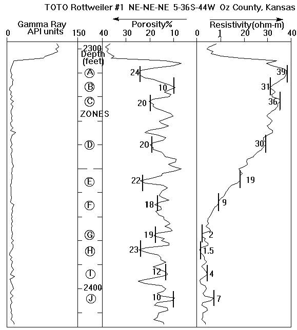 |
| Figure 1: Gamma ray, porosity and resistivity logs of a section of Rottweiler Formation (Triassic), a hypothetical oil-productive sandstone |
The Pickett plot is made on conventional double logarithmic (to base ten) scale graph paper. An examination of a crossplot of the porosity and resistivity values of the ten zones (Figure 4) shows a pattern that is easy to interpret. Zones A to E have much higher resistivities than zones H to J, even though they have similar porosities, and suggests that these zones may have appreciable hydrocarbon content. Zone F is intermediate between these two clusters, and its depth relationship to them indicates that it may be in a transition zone. The zone H-J trend of a systematic decline in resistivity with porosity also favors their interpretation as possible water zones.
These qualitative generalizations can be made considerably more specific, using the mathematical properties of the graph form and its ability to represent many useful petrophysical relationships. The basic method for the plot that bears his name was described by Pickett (1966). In a later paper, Pickett (1973) described in detail the pattern recognition properties of the plot which made it a particularly powerful method for log interpretation. The mathematics of the Pickett plot are simpler than those of the Hingle plot (Hingle, 1959), and is another transformation of the Archie equation:

Rearranging the Archie equation and substituting the resistivity
index, I, gives : 
Taking logarithms, the equation becomes: ![]() which describes a family of parallel lines for different resistivity index
values whose slope is the negative of the cementation exponent (-m). When
the resistivity index, I is unity, the line is the water line with an intercept
equal to a*Rw. Other resistivity lines are displaced to the northeast and
are drawn easily as lines parallel to the water line and with resistivities
which are the water line resistivities multiplied by the index at common values
of porosity.
which describes a family of parallel lines for different resistivity index
values whose slope is the negative of the cementation exponent (-m). When
the resistivity index, I is unity, the line is the water line with an intercept
equal to a*Rw. Other resistivity lines are displaced to the northeast and
are drawn easily as lines parallel to the water line and with resistivities
which are the water line resistivities multiplied by the index at common values
of porosity.
In common with most visual methods, these concepts are more obvious when sketched out graphically, as in figures 5 to 7. The water line can be established by eye, or numerically, by stipulating the formation water resistivity, Rw, and the Archie constants of a and m (Figure 5). Many log analysts prefer to work with the value of a held at a value of unity. Using this convention, the intercept is equated directly with Rw, and the slope of m becomes an average estimate of cementation factor within the reservoir. If a trend of (relatively) low resistivity points is suspected to sketch out a water line, then the exact position can be established through the selection of water resistivity and Archie constants that are most compatible with preexisting knowledge while simultaneously honoring the graphed data points in a convincing manner. (The use of an interactive graphics computer program is most effective for this type of operation.)
In our hypothetical example, the intercept of the water line predicts a formation water resistivity of 0.10 ohm-m and a cementation factor, m, of 1.8 (assuming the a constant to be one). In a real analysis, these numbers would have local implications that could be assessed for credibility. The cementation factor of the “Rottweiler sandstone” implies that the sandstone is moderately cemented; the formation water resistivity would be compared with available measurements of Rottweiler water resistivities in the immediate area.
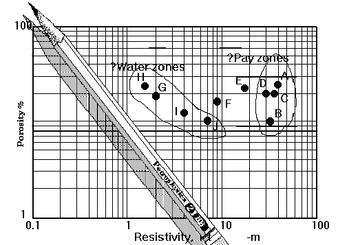 |
Figure 4: Plotting zones on a Pickett Plot |
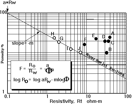 |
Figure 5: Location of the "water line" |
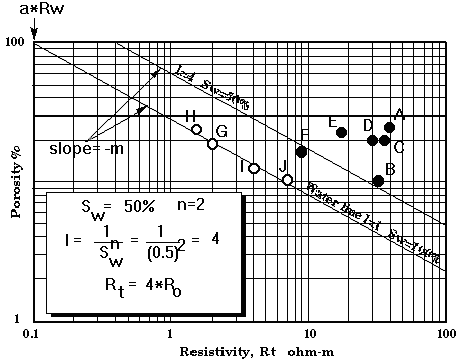 |
Figure 6: Location of the 50% saturation water
line |
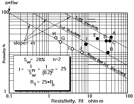 |
Figure 7: Location of the 20% water saturation
line |
The location of other water saturation lines will be on the higher resistivity side of the water line (which is the 100% water saturation line). They all have the same slope of -m, and so are parallel. The resistivity index, I, for any given water saturation determines the value of Rt on the associated line at any porosity as a multiple of Ro on the water line at the same porosity. This concept is explained graphically on figures 6 and 7.
Crossplotted points that lie above the water line have water saturations of less than 100% and complementary hydrocarbon saturations. However, their location on the plot does not immediately answer the question concerning the fluids the zones will produce when either tested or perforated. Water free hydrocarbons, water-cut hydrocarbons or water alone are all possibilities. The product of porosity and water saturation is the bulk volume of water (BVW) which can give important clues to producibility when related to pore character and reservoir type.
As an additional feature, each pair of contiguous zones on Pickett plots generated by PfEFFER are linked by a straight line segment. Taken collectively, the lines sketch out a trace that is the reservoir "trajectory" in the depth dimension of the covariation of resistivity and porosity. Trends, deviations, cut-backs and other features of the trajectory give important clues regarding hydrocarbon column structure, reservoir heterogeneity, cyclic repetition, and changes in pore size.
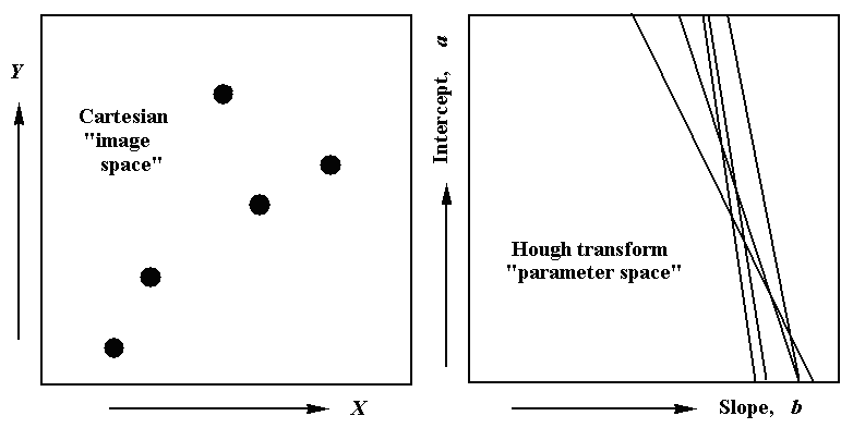
Although the Pickett plot has many useful properties for pattern recognition, there is still room for improvement. When fitting either the water line or a line of irreducible saturation, the resulting values of cementation and saturation exponents are not immediately obvious, but must be calculated from the slopes. The normal range of porosities also means that there is often a fair degree of uncertainty in the estimate of water resistivity when extrapolating to the intercept at 100% porosity. An alternative approach to this problem is through the use of the Hough transform, by plotting the data directly in parameter space.
The Hough transform was introduced by Hough (1962) as a means to detect
patterns of points in binary image data. The basic concept is very simple,
which is an immediate recommendation of its power. When searching for trends
such as straight lines in a plot of X–Y coordinate data, the original
points can be considered to be represented in "image space," although
the purpose of the analysis is to extract the parameters of any systematic
features. If parameters are the goal, then the problem can be simplified by
replotting the data in "parameter space." The basic idea can be
clarified by referring to Figure 8. Here the task is to locate any linear
trend through the set of points plotted in X–Y Cartesian space. A line
is specified by the equation: Y = a+bX
where is the intercept and is the slope. The objective of the Hough transform
then becomes to replot the data in parameter space, rather than X–Y
image space. Any single X–Y coordinate pair can be "back-projected"
as a line on an plot which gives the slopes and intercepts of all possible
lines that could pass through this point. The equation for this line is found
easily by rearranging the Cartesian space equation as: a = Y-bX
where X and Y are now fixed and the intercept a and the slope b are variables.
Each point in Cartesian space is now a line in parameter space and the intersections
of lines mark slopes and intercept values of lines that pass through two or
more points in Cartesian space. Therefore, a linear trend through a subset
of data on a Cartesian plot will be marked by a bundle of lines whose intersections
are clustered in the area of a representative common slope and intercept.
Now that the basic concept of the Hough transform has been explained, we will follow its application to the Rottweiler Sandstone data. The parameters of the water line are the water resistivity intercept (assuming the constant " " to be unity) and the cementation exponent slope. We can combine the concepts of the reconnaissance water resistivity (Rwa) and the reconnaissance cementation exponent in a single equation: log(Rt) = log(Rwa) - ma*log(f)
This equation describes every possible line that could be drawn through the resistivity-porosity coordinates of either a water zone or a hydrocarbon zone. When mapped into the parameter space of water resistivity and cementation exponent, each zone that plots as a point on the Pickett plot becomes a line on the Hough transform. Water zones should be recognized as a bundle of sub-parallel lines with lower Rw and m values than other zones. Ideally, the water zone lines would have a mutual intersection at the coordinates that locate the true formation water resistivity and cementation exponent. In reality, the ragged trend that characterizes most water lines results in a range of possibilities which is an accurate reflection of the spread of alternative lines that could be drawn as possible water line on the original Pickett plot. The advantage of the Hough transform is that it immediately gives the values of all possible combinations of Rw and m and, since both of these have petrophysical meaning, this aids the analyst in his/her selection of the most likely pair. This discussion can be understood by thoughtful examination of the Hough transform of the Rottweiler Sandstone data shown in Figure 9.
Although the Hough transform is a pattern recognition method in its own right, its application to the Pickett plot as described here can equally be considered as a "universal Rwa plot" in which all possible values of cementation exponent within a petrophysically reasonable range are applied successively in the computation of corresponding Rwa values from zone resistivity-porosity log values. This is the spirit in which the Hough transform option is implemented in PfEFFER in which the cells of a grid of Rw (rows) and m (columns) are filled with frequencies of occurrence of values generated when mapping logged zones into the parameter space. As a result, the Hough transform lines are sampled discretely and individual cells will tend to have higher counts at parameter value combinations where several lines converge or intersect. However, as stated already, the interpretation of these plots should be made with reference to what is known and/or what is reasonable concerning the reservoir formation's cementation exponent and water resistivity.
 |
| Figure 8: Simple example of a Hough transform applied to the projection of points in Cartesian "image space" into a parameter space of slope and intercept. |
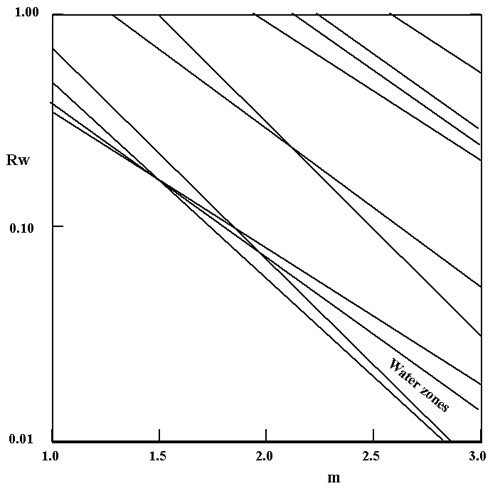 |
| Figure 9: Hough transform of the Rottweiler Sandstone resistivity-porosity data into the parameter space of formation water resistivity (Rw) and Archie equation cementation exponent, m. |