![]()
Prev Page--General Geology || Next Page--Stratigraphy
Chapter V—Production of Oil and Gas
Introduction
The modern business of oil and gas production is in its present state a rather complicated and highly developed industry. There are many important factors to success, and the large companies are organized with minute attention to all the various details connected with the business. In the development of a new oil or gas pool, for example, the geologic structure is first located and carefully mapped by the geologists. Oil and gas leases on the lands overlying the structures are obtained, and when all the desirable land has been secured, drilling rigs are brought in for boring the wells. When a well is completed and oil or gas encountered, it is necessary to arrange for the storage or the disposition of the materials obtained from the well, involving the arrangement for pipe-line transportation or tank storage. Large oil companies operating in any of the fields such as those of Kansas and Oklahoma have separate departments devoted to geologic exploration and mapping, leasing, drilling, pipeline and tank storage, buying, engineering, refining, and marketing.
In the case of an oil strike by any individual or company, the first step of the oil operator is to lease land as near as possible to the producing well. If he has knowledge of the geological structure of the area he will follow the trend of the anticline or terrace, and if he feels that the properties are within the limits of possible producing territory he may make locations and start drilling. In many cases, however, land is leased merely because it is in proximity to a producing well, and in the rush to newly proved areas many inexperienced operators, by lack of knowledge both of the nature of the business and of the underground conditions, are led to failure. It is often the case, however, that the inexperienced operator, or group of operators, is responsible for the location of new areas by wells of the "wildcat" type.
It should be noted carefully that none of the large oil companies at present engaged in oil operations in any of the large oil fields drill wells in entirely unproved territory without any knowledge of the geologic structure. A wildcat well drilled without any knowledge of the underground conditions, and at a distance from producing areas, is a speculative hazard of the most extreme sort. Consequently, in any area which it is desired to test, reference to all available geologic advice should be had at the very outset.
Leasing
There are no set rules nor any strictly uniform practice in the matter of leasing. As this is necessarily more or less dependent upon local conditions, the oil men deal entirely with the individual landowners, and the oil leases are private bargains. The unit areas of the lease are the simple and uniform land divisions of the civil townships of thirty-six sections into which Kansas is divided. The sections are subdivided into tracts of multiples of ten or twenty acres.
The usual form of oil and gas leases in Kansas grants to the oil producer, or lessee, the irrevocable and exclusive right to seek for oil and gas on the area covered by the lease, the length of the lease ranging from one to five years and "as long thereafter as oil and gas is produced in commercial quantities." In many instances the lease is taken for a period of five years with option of extending the lease as production continues.
For the right thus given the landowner or lessor is paid one dollar to make the contract legally binding, and in addition such other considerations as may be desirable, varying with the particular case. The additional compensation to the landowner may be arranged for in a number of different ways. A stated consideration may be paid to the landowner for each acre, in addition to which a bonus of varying amount, depending upon the probability of the production of the lease, is in many cases given. In other cases the lessee may arrange to pay so much rent per year for the lease, thereby holding it until it expires. The most important feature, however, in the compensation of the landowner is the royalty, which consists in the payment of a stated fraction of the gross production or profits of wells on the lease. This may, according to stated agreement, be paid either in cash or in oil. In actual practice these various forms of remuneration for the right of drilling supplement each other in various ways according to the agreement of the particular lease. For example, in a lease where a large bonus is paid the royalty will probably be rather low, or if a small price is paid for the lease a large share of royalty may be exacted. In general the price and the details of the lease contract depend upon the nearness to producing territory and the probability of production in the area leased. In purely "wildcat" regions the bonus is seldom considered, but in a district which is located near good production a large bonus may be given. In addition to the customary royalty of one-eighth or one-sixth, bonuses as high as $150 to $200 per acre have been paid. In the Cushing field, Oklahoma, in one instance a royalty of 50 per cent was given without bonus.
In the case of producing gas wells the amount and method of payment of the remuneration to the landowner are somewhat variable. On an average about $100 to $150 per year is paid for each gas well, stipulations being made with regard to the use of the gas by the landowner and his payment for gas used.
In general a landowner desires to have a test well drilled at as early a date as possible. Rental leases are therefore somewhat in disfavor, because the oil operator under these circumstances has the right to drill or not to drill at his pleasure. The common rental for commercial leases is $1 per acre per year. In some cases the leases have been so drawn that by payment of 25 cents per acre annually after the expiration of the first period of time the lessee may continue to lease for five or ten years, or indefinitely.
In many leases a time is set for the beginning and completion of a well, a clause being inserted to the effect that drilling shall begin within ninety days and be completed to a specified depth within a given period, providing that oil and gas is not found in paying quantities above this depth. A clause may also be inserted requiring some sort of systematic continuation of drilling and development of the lease. In some cases a bond is required of the lessee as guaranty to the landowner of the fulfillment of the terms of the lease in payment of royalties, rentals and damages.
In the leasing of land for oil and gas the lessor retains all surface right to the land except on the portion which is necessarily used by the operator for his equipment including the full number of wells, power house, boiler house, tankage, waste pit and pull rods. Upon an eighty-acre tract not more than five or six acres are necessary for this. In a considerable part of the oil fields the land is not considered sufficiently valuable from an agricultural standpoint to make it necessary to place any restrictions upon oil and gas operations. In certain portions of the field, however, farmers till the land and at the same time derive an income from the oil. Where the land adjoining producing oil wells contains a growing crop it is agreed that the lessee is responsible for all damages to the crop, provided they reach a sufficient amount to warrant complaint. Pipe lines are buried below plow depth, but the pull rods from the power house to the various wells are sometimes a source of more or less bother because they run close to the surface.
After production has been established the lease becomes one of the most valuable parts of the oil property. It may be sold or transferred at the option of the lessee, the price depending upon the number of producing wells and their average daily yield. Transfer of leases also takes place even before wells have been drilled, the price being dependent upon the distance from proven property. Lease speculation has become a rather lucrative business at the present time, especially in newly opened districts. The speculator closely watches the prospecting and development, and on news of an oil strike rushes to the locality and leases all available property with as little expense as possible. When the operators who really wish to drill come to the field later they are forced to pay the speculator's price. Examples of this speculation may be seen in every newly opened oil district and have been common in the Kansas and Oklahoma fields.
A typical form of the leases used in Kansas is given in the Appendix. The recent development in the production of natural-gas gasoline makes necessary provision for royalty to the lessor in this regard.
Location of Wells
After a favorable geologic structure has been located and leases have been secured the operator must choose the location of the wells to be drilled. In the case of the first wells the selection of sites should be governed entirely by the geologic information which is available, the wells being located over the central portion of the anticline or dome. Such wells will form the most satisfactory test of the structure.
In cases where detailed geologic information is lacking, or where the entire area of a lease is likely to be productive, the wells are placed according to generally recognized rules and courtesies among the operators, or with reference to local conditions, such as the character of the topography. Wells are commonly placed about 200 feet within the boundary line of the lease, but this distance varies, with the depth of the sand and other considerations, from 100 feet to 330 feet. Since it is common practice to lease oil and gas land in multiples of 10 acres, which equal blocks 660 feet square, there is a tendency, especially in the Midcontinent field, to put down wells at a distance of 660 feet from each other. In shallow sands they are located at greater distances apart, about 1,320 feet being an average interval. In large parts of certain fields, like those at El Dorado and Augusta, in Butler county, the wells are located with mathematical precision in rows and cross-rows. It is customary to place the wells on one lease directly opposite those on an adjoining one, in order to protect property lines and to prevent drainage of oil from the lease. This practice is termed "offsetting."
In practically all of the producing fields many wells have been drilled at distances much too close together. In one district in Oklahoma probably one-half million dollars has been spent on unnecessary wells within an area of two square miles. No general rule applicable to all districts can be given, the proper distance depending largely on certain local conditions, which must be determined largely by close watch of wells drilled later among older wells. If the reservoir stratum is not very porous, gas or oil may drain into the well rather slowly and from a limited area. Wells recently drilled in the Iola gas fields show a surprisingly large production, almost equalling the yield of wells first put down. This indicates the limited area drained by wells in this district. On the other hand, oil and gas may move readily a considerable distance through a very porous reservoir rock.
When oil or gas has been discovered in one well there is still urgent need for accurate geologic information for use in the location of new wells and in the making of leases, that there may be a minimum of dry holes and that additional leases secured may be the most profitable.
As a rule, leases are obtained and wells are located as close to the producing wells as is possible, on the strong probability that the oil and gas reservoir will also be encountered by drilling on adjoining properties. However, a reservoir usually extends a considerable distance farther along one line than in other directions, and a knowledge of the geologic structure is all important in the scientific location of wells and in the development of adjacent areas. As soon as an important oil strike has been made the price of leases in the vicinity usually advances at an exceedingly rapid rate. It is consequently a difficult matter in certain instances to know whether it is better to pay a high price for leases in close proximity to producing wells or to invest in lower-priced leases at greater distances with correspondingly greater risk. The various factors entering into this consideration have been studied by Roswell Johnson (Johnson, 1916; Johnson, 1914). A statistical investigation of a number of pools in the Appalachian field indicates a rather rapid decline of production in this region for distances from three to six miles from the first well, and a more gradual decline at greater distances. So many are the variables, however, that no general statement of this nature as applied to pools in the Midcontinent field can be made. It is, of course, almost certain that within the general area of a pool a number of the wells will prove dry or will contain only water. Consequently, the mere location of a lease in the general area of an oil or gas pool is by no means a guarantee of oil or gas production,
In general the conditions most similar to those observed in the discovery well will be observed at the same level in the rock strata in either direction along the strike of the rocks; The reservoir is likely to persist in this direction and a uniformity of conditions will probably obtain.
Since gas, oil and water in the rocks tend to arrange themselves in distinct layers in the order of their specific gravities, it is evident that gas, if present, may be expected in the uppermost parts of the reservoir, oil at points lower down on the dip, and water in the lower portions of the porous stratum. Consequently, if a well yields only gas, or gas with a little oil, an oil-producing well may be sought at a point down the dip of the reservoir, or if a well encounters water, or water and a little oil in the reservoir rock, an oil-producing well is most likely to be found higher up in the structure,
Since the productive pools in a reservoir usually have a greater extent in one direction than at right angles to it, careful observation of the production and rate of production of the wells may indicate to the producer the direction of this axis, and therefore suggest the most favorable line of development.
If pressure persists after a long flow, evidence of the existence of an undrilled extension of the reservoir is highly probable.
Drilling for Oil and Gas
Method of Drilling
After a favorable geologic structure has been found and leases have been secured comes the operation of drilling. The methods of drilling are various and have been developed to suit the particular needs and conditions in different fields. In a region of soft, unconsolidated strata, such as parts of California or the Gulf coast, the rocks are easily penetrated by a special type of drill, but in regions of hard strata, such as the Midcontinent or Appalachian fields, this drill can not be used successfully and other methods must be employed.
The system almost exclusively used in Kansas and Oklahoma is the so-called "Standard" or cable drilling, which consists essentially of a heavy steel bit attached to a manila or wire cable, which is raised and dropped by means of a walking beam extending over the hole. It is especially adapted for drilling into hard formations or those sufficiently consolidated that the sides of the hole will not cave. Under these conditions drilling may be continued until it is advisable to case off a water- or gas-bearing stratum. In comparatively shallow territory a portable machine of the "Star" or "Parkersburg" type is frequently used in the Kansas and Oklahoma fields (Plate IX). These have the advantage of being moved about easily where roads are bad, with less loss of time than with a heavy regulation outfit, but is not adapted for handling heavy strings of cable. The time saving and the cheapness with which such a machine can put down a well from 1,000 to 1,200 feet especially adapts it for developing shallow territory.
Plate XVII—Standard drilling outfit, coupled for raising tools. (After Bowman, U. S. Geol. Survey.)
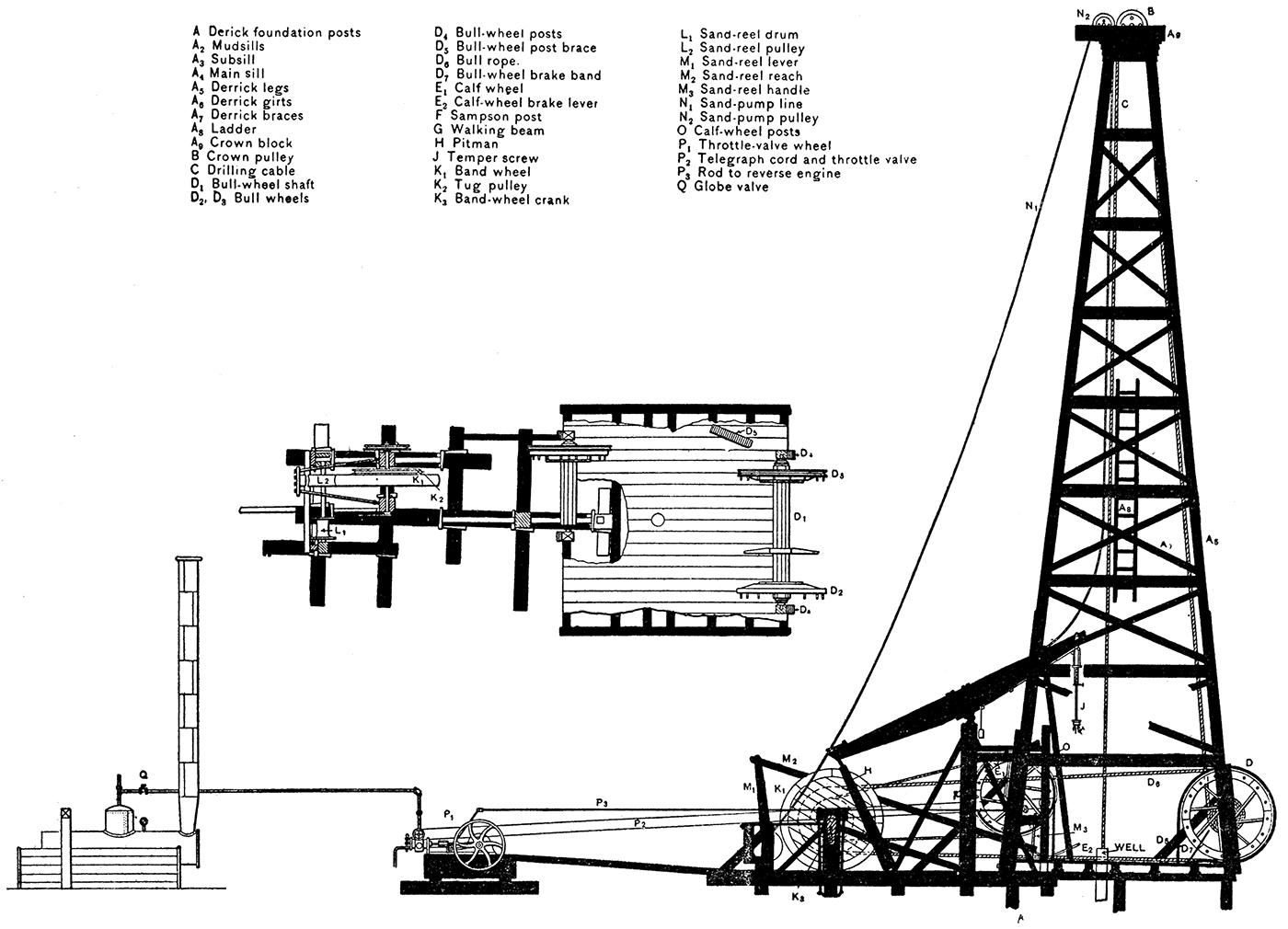
Plate XVIII—Drilling tools. 1, Augur stem; 2, spudding bit; 3, drilling bit; 4, bailer; 5, temper screw; 6, drilling jars; 7-8, underreamer, closed and open; 9, joint; 10, elevator, for lifting casing into derrick. (Lucey.)
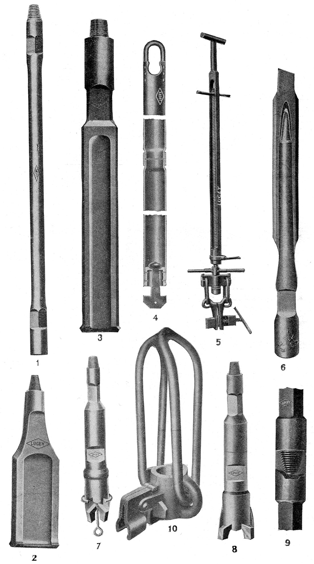
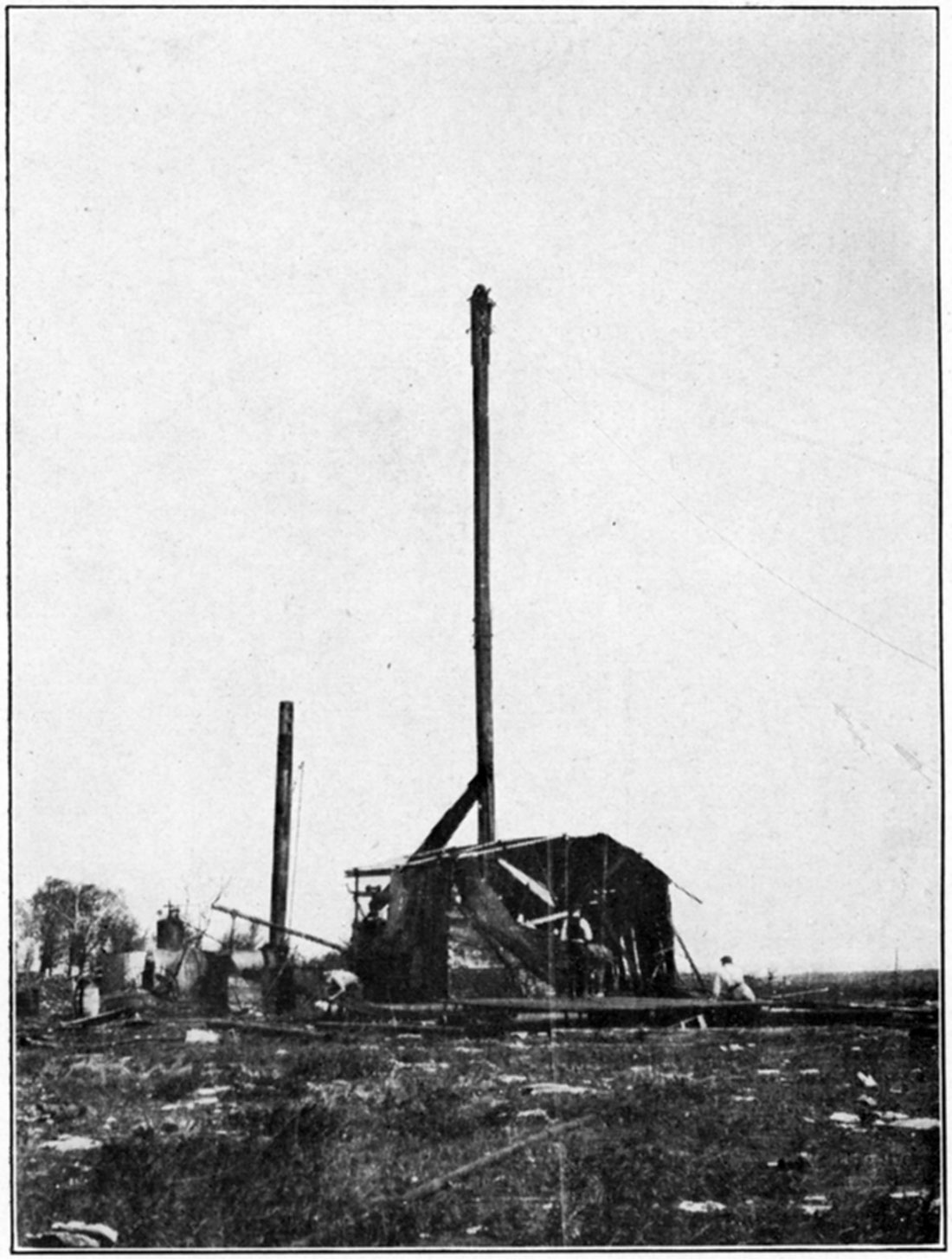
Plate IX—Star drilling rig, south of Sedan.
The site of the well having been selected, the first operation in drilling is the erection of the rig (Plates V, VI and VII). The main portion of this is the derrick, which consists of four strong uprights converging toward the top, held in position by ties and braces and resting on a strong foundation of concrete piers or wooden sills. For drilling the deeper wells the derrick is at least seventy feet high, on account of the length of the "string" of drilling tools, and from twenty feet wide at the base to about four feet at the top. The derrick is surmounted by the crown block, bearing the pulley over which the drilling cable passes, and the sand-pump pulley.
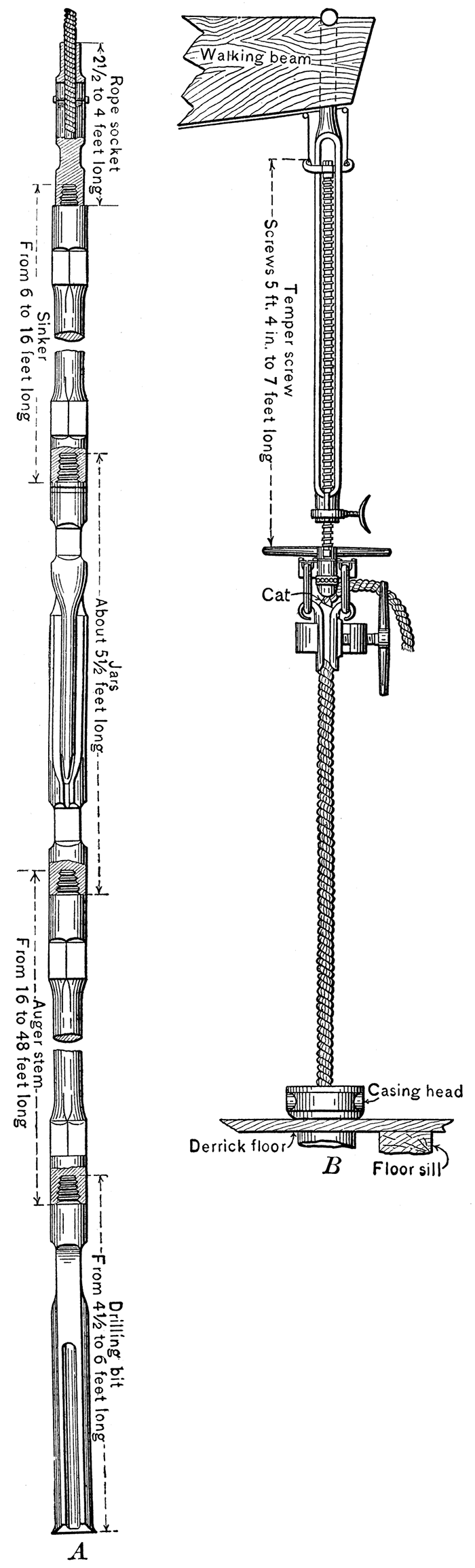
The parts of the rig actually employed in the operation of drilling are, in addition to the drilling tools and cable, the temper screw (Fig. 12, B), which grips the cable and adjusts its length to the depth of the hole; the walking beam, to one end of which the temper screw is attached; and the large wooden jack or band wheel, which gives power to the walking beam and other parts of the rig (Plate VII). The temper screw is gradually turned as drilling goes on, increasing the depth of the tools from the surface. When the entire length of the screw, amounting to about five feet, has been let out, the tools are withdrawn and preparations are made for the next "run." The walking beam is a massive timber, measuring from sixteen to twenty-four feet in length, which gives the vertical motion to the cable and string of tools. It is supported in the middle by the upright samson post and connected at the end opposite the temper screw by a pitman rod to a crank on the band wheel. The motion of the band wheel thus moves the walking beam alternately up and down. The drilling machinery is very simple, but the effectiveness of the drill is due to the peculiar form of the drilling tools and the skill used in handling them.
Figure 12—A, String of tools used with standard drilling outfit. B, Temper screw. (After Bowman, U. S. G. S.)
After the tools have drilled the length of the temper screw into the rock it is necessary to draw the tools to the surface and bail out the sandy or muddy debris at the bottom of the well. For this operation an entirely different arrangement is necessary, the portions of the rig used being the bull wheel on which the drilling cable is wound, the crown pulley at the top of the derrick, and the band wheel which is connected to supply power to the bull wheel. The bull wheel consists of a reel on which the drilling cable is wound and an attached wheel on either side, one of which carries the driving belt from the band wheel, the other bearing a stout iron band brake by which the speed of the reel may be controlled. The cable, having been loosed from the clamps of the temper screw, runs directly to the crown pulley from the well, thence down to the bull wheel at the side of the derrick, and as the cable is wound on the reel the long string of tools are lifted out of the well up into the derrick. When the tools have been thus withdrawn the well is ready to be bailed.
The operation of bailing the well consists simply in lowering a sand pump or bailer by a separate line from the sand-reel pulley at the top of the derrick, allowing the bailer to fill and drawing it again to the surface. The bailer is a plain cylinder of light galvanized iron, with a bail at the top and a stem valve at the bottom (Plate VIII, 4). As this projects beyond the bottom it automatically fills the bailer when lowered to the bottom of the well and empties itself when rested on the bottom of the waste trough at the surface. The average length of the bailer is about six feet, but some are fifteen or twenty feet. When the well has been bailed the well is ready for further drilling.
In some standard rigs, especially those used in California, an additional wheel, known as the calf wheel, is located opposite the bull wheel. It is used for handling casing, and saves much time because it obviates the necessity of disconnecting the tools from the drilling cable and the use of the bull wheel for this work.
Beyond the derrick and the other parts of the rig is the engine, which furnishes power to the band wheel by a belt. Steam power is almost universally used in the drilling of oil wells, the steam being supplied by a boiler located at a distance from the well in order to decrease the danger of fire. The engine is controlled from the derrick. Water for the boiler is obtained from a near-by water well or neighboring stream, but in some cases the matter of water supply is a serious difficulty and greatly hinders or delays the drilling of the well.
The string of tools used in deep-well drilling consists of several parts, all of which have certain definite functions and are the outgrowth of years of experience. A full string comprises a rope socket, sinker bar, jars, auger stem and bit (Fig. 12 and Plate VIII). The socket is used to attach the end of the drilling cable firmly to the drilling tools, the methods of attachment varying rather widely in different cases. The sinker bar is a long, heavy bar used to give added weight to the drill and to keep the hole straight. It was formerly thought to be essential to the string of tools, but is now used only in wet holes. The jars are in many respects the most interesting and important portion of the apparatus (Plate VIII, 6). They consist essentially of a long double link with close-fitting but freely moving jaws, which may be compared to a couple of flattened and elongated links of chain. The links are about thirty inches long and are interposed between the heavy iron auger stem carrying the bit and the upper bar. The principal use of the jars is to give a sharp jar or jerk to the drill on the upstroke so that the bit is dislodged if it has become jammed in the rock. The drill responds to the powerful upward blow of the jars as they are jerked violently together by the stroke of the walking beam when it will not yield to the slow and relatively steady pull of the rope. The jars are not used to drive the drill into the' rocks, such practice at the hands of an inexperienced driller invariably resulting in serious damage to the links within a short time. The auger stem (Plate VIII, 1) gives additional weight to the blows that are struck, and also, by increasing the length of the drill, helps to maintain a straight hole. The.drilling bits are of various patterns, according to the character of the rock that is being penetrated. A short, light bit is used in the preliminary drilling, known as "spudding" (Plate VIII, 2). All the joints of the string of tools are fitted with taper-screw joints, so that they may be fastened together firmly with a few turns.
The operation of drilling an oil well as practiced in the Midcontinent field may be described briefly. After the rig has been built the preliminary drilling, known as "spudding," is begun. For this a short, light bit is attached to a cable, which is run through the crown pulley at the top of the derrick and fastened to the bull-wheel shaft. The up-and-down motion to the spudding drill is given by a rope called the jerk line, which is fastened to the wrist pin of the band. wheel and attached by a curved metal slide, called a spudding shoe, to the part of the cable which extends from the crown pulley to the bull-wheel shaft. By an adjustment of the length of the jerk line, each revolution of the band wheel results in a pull and subsequent release on the drilling cable, which causes a corresponding rise and fall of the tools. As the hole is deepened the cable is let out by a partial turn of the bull-wheel shaft. Spudding is much harder on the derrick than ordinary drilling, because the entire strain comes at the top of the derrick, while in drilling with the walking beam the weight and jar of the tools is borne by the samson post.
After the hole has been deepened by spudding sufficiently to permit the use of the regular string of drilling tools, this distance amounting on the average to about 75 or 100 feet, the drilling cable is rigged to the walking beam by the temper screw and the regular work of drilling is begun. The pitman of the walking beam is fastened to the crank of the band wheel, and the beam begins to raise and drop the tools at the rate of about twenty-five strokes a minute. In the earlier drilling, when the length and therefore the spring of the cable is less, a shorter stroke is used than when the well has been drilled to greater depths.
The operation of drilling is frequently interrupted by the occurrence of an accident which necessitates the use of fishing tools of various sorts. If the fishing is successful, drilling is resumed, but if unsuccessful the well must be abandoned, often after weeks or months of labor.
Casing
A very important consideration in the drilling of a well is the casing, which protects the hole from caving and keeps out water. In many places where the surface material consists of a loose sandy clay or similar material a conductor box or large iron pipe is sunk to bed rock. This facilitates the work of drilling the deeper portion of the well. The strata in the deeper portion of a well are, as a rule, made up of alternating layers of hard and soft beds, porous or slightly porous, and water-bearing or without water. Unless the water in the rocks is under considerable head it is welcomed by the driller, for it saves the trouble ~.nd expense of pouring water into the hole to keep the drillings liquid. If the water coming into the hole is too great it is necessary to lower a string of casing from the surface to the first non-water-bearing rock below the water-bearing strata. The casing is set very hard into this lower layer, shutting out the water. Further drilling necessitates the use of a smaller bit which will pass within the diameter of the casing. If other heavy flows of water are encountered they must be cased off in a similar way. In some deep wells through porous water-bearing strata as many as eight or ten different strings of casing are necessary.
In comparatively shallow territory a well is sometimes drilled "wet," the water sands not being cased off and the tools running in a hole in which the water stands high. If the sides do not cave, casing may not be put in until the well is finished. Drilling under these conditions is, however, considerably slower and only rarely justifies the saving in labor and expense of casing.
Several varieties of casing are used. Sheet-iron riveted pipe is used in some foreign wells, but in American fields is almost unknown. Casing most commonly used in the Midcontinent fields consists of sheet-iron pipe of various sizes and rather uniform weight. The ends of the sections are threaded, so that one section may be attached firmly to the preceding. The diameter of the casing pipe varies from three or four inches to more than eighteen inches.
Drilling Contracts
For the drilling of a well a contract is made between the operator and a drilling contractor on the basis of a certain price per foot, the amount of which depends on the locality and the depth of the desired oil sand. The rate is fairly uniform in an active field, but in "wildcat" areas the rate is usually higher. Stipulation is commonly made in the contract for drilling to a specified depth, the contractor being held responsible for reaching this depth. The agreement usually calls for the commencement of drilling within a given time. The contractor purchases and constructs the derrick, furnishes tools, fuel, water, boiler and engine, and hires the drillers and tool dressers. He is held responsible for accidents. Oil or gas which is found during the process of drilling may be used as fuel by the contractor. In general he is required to handle all the necessary casing, and in case of a dry hole must pull out all the casing possible. The operator furnishes drivepipe, casing, and whatever rodding or tubing is necessary, provides for the hauling of the pipe and other accessories, except the derrick and driller's tools, and is responsible for plugging a dry well and filing affidavit thereto.
A typical form of drilling contract is given in the Appendix.
Cost of Drilling
The cost of drilling varies notably in different fields, and under certain conditions may fluctuate widely even in the same field. The controlling factors are in general the depth of the well, hardness of the strata or other conditions increasing the difficulty of drilling, distance from supply center, and availability of working supplies such as fuel, water, etc. In the case of individual wells the cost may be from 50 to 100 percent higher on account of unusual underground conditions or accidents. In general the drilling of an isolated well in the first development of a property costs more than later wells, because many items necessary for the first well may be used a second time in the drilling of adjacent wells.
Drilling is commonly contracted for on the basis of number of feet, the average cost in the Midcontinent field being from 70 cents to $2 a foot, depending on the depth, conditions of transportation, fuel, water, caving, formations, and number of strings of casing necessary.
In shallow wells where a light rig of the churn type may be used the cost is materially reduced on account of the lack of any need of an expensive derrick. In the greater portion of the Kansas fields, however, it is necessary to use a standard rig and derrick. Wells completely equipped to produce cost the owner from $1.85 to $3 per foot, the average being about $2 or $2.50.
The cost of a portable rig is about $2,300. A larger type of portable rig has been perfected recently, capable of drilling to greater depths. Its cost is about $10,000. Wells drilled by the lighter rigs of this type cost very much less, on the average, because of the lack of any need for derrick and other parts of the larger standard rig.
The following figures were obtained from a company operating in the El Dorado field in May, 1917, and give the prices in effect at that time:
| Cost Data on Well Drilling, El Dorado Field, 1917. | |
|---|---|
| Cost of drilling a deep test, not including casing, approximate depth 2400 feet | $6,500.00 |
| Cost of drilling shallow well | $800.00 |
| Cost of Casing | ||
|---|---|---|
| Diam. of pipe, inches |
Weight per foot, pounds |
Cost per foot |
| 12 1/2 | 50 | $3.33 |
| 10 | 35 | $2.14 |
| 8 1/4 | 28 | $1.75 |
| 6 5/8 | 20 | $1.21 |
| 5 3/8 | 17 | $1.02 |
| Cost of installing 600 feet 12-1/2 in. casing | $25.00 |
| Cost of installing 1,500 feet 10-1/2 in. casing | $35.00 |
| Cost of installing 2,200 feet 8-in. casing | $50.00 |
| Cost of installing 2,400 feet 6 5/8-in. casing | $50.00 |
| It takes all of these different sizes of pipe to complete the well. | |
Keeping the Log
One of the greatest needs at present in the scientific development of the oil and gas fields of the state is good well logs. Every log should give the top and bottom of every sand that carries gas, oil or water, in addition to giving the distance from the top of the sand to the level where the flow into the well is found. The character of other strata passed through, especially those of prominent horizons such as limestone formations and coal beds, should be noted and described as carefully as possible. When drilling is begun in a new field the logs, with samples of drill cuttings, should be studied carefully by a competent geologist in order to determine as accurately as possible the underground conditions and to advise with regard to further development. The State Geological Survey may act as a clearing house for such information, and may then give assistance in the correlation of formations, in determining the depth to given formations in various localities, the direction of the dip of the strata and other features. Without care in recording the information obtained by drilling and without the assistance of a geologist the best results can not possibly be attained.
Shooting the Well
When the drilling of a well has been completed in rather close-textured reservoir rock, or when the production of a well has begun to decline, it is common practice to "shoot" the well, a charge of nitroglycerine being generally used for the shooting. The amount of explosive used varies from a few quarts to 60, 80, 100, or even 250 quarts, and is placed in specially designed canisters. The canisters are lowered to the bottom of the well and discharged by dropping a nitroglycerine "jack squib" carrying a fulminate cap, which explodes on striking the torpedo at the bottom of the well. Formerly the percussion cap was placed with the charge at the bottom of the well and the torpedo was exploded by dropping a conical piece of iron-the so-called "go-devil"upon the charge.
It is a matter of considerable importance, as shown in practice, to locate the nitroglycerine charge in the pay sand rather than allowing it to extend above into the barren formations. If the latter is shattered and falls over the pay sand it may interfere very greatly with the operation and production of the well. The use of too large a charge in the hope of thoroughly shattering the pay sand in a considerable surrounding area may so disturb and break the barren formations as to make the well valueless.
Management of Oil Wells
The problem of management of the oil well involves (1) the method of recovery of the oil especially as practiced in the Midcontinent fields; (2) the more or less rapid but continuous decline from the initial production, the typical life history of all oil wells; and finally, (3) the manner of handling the oil after it has been brought to the surface.
Method of Recovery.
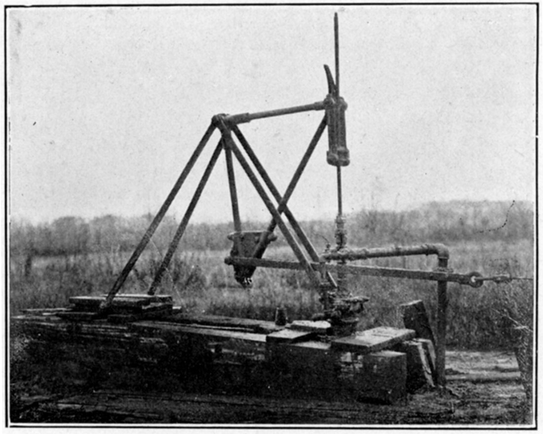
In certain parts of the Kansas oil fields the oil reaches the surface under its own pressure. Wells from which the oil thus flows are known as "gushers," and, especially when the pressure is very great, are much the most spectacular part of an oil field. The oil does not long continue to flow under its own head, even when the initial pressure is very great, and it then becomes necessary to pump the wells. The great majority of wells in the Kansas oil fields are of the pumping type, the method of pumping, however, varying rather greatly in different cases. Some wells are pumped by motive power-steam, gas, or gasoline engine-which is located at each well. This demands a separate power unit for each individual well. In other cases a central power plant supplies steam or compressed air to a number of pumps operating wells located around the plant. The central plant may be connected with the individual pumps by shaft or pull rods, which are so fastened to the operating drum at the plant as to compensate one another and make a minimum load on the engine. At the wells are pumping "jacks" of various design which convert the horizontal pull of the rods to a vertical movement of the sucker rods in the well. Typical pumping arrangements are shown in the accompanying plate (Plate X).
Initial Production and Decline of Oil Wells
It is impossible to determine with any degree of accuracy the life of an individual oil well, but it is possible, by means of accurate records of the history of wells, and of the pool containing them, to obtain an approximate estimate as to the length of time during which the well or pool will be productive. A record of the production of an oil well always shows a maximum yield at its very beginning or immediately after a successful shooting of the well. The production then drops off, suddenly at first, and then declines more gradually. Minor irregularities in the plotted production curve may be due to the influence of neighboring wells or special conditions. In most cases a record of the production of an oil field, on the other hand, shows a gradual rise to a maximum, followed by a gradual decline. The increase in production at first is, of course, due to an increased number of wells as the field is developed. When the declining production of wells already drilled is not compensated by production of new wells the total production of the field begins to decline. The large initial production of many oil wells is evidently due to the strong pressure in the oil reservoir when the wells are drilled in. The duration of the period of greater production depends upon local conditions, such as the porosity and structure of the sand, the development of the pool, the position of the well, and the character of the oil. With decline in pressure production gradually decreases in many districts to a fairly constant amount. Decreased production is due to decline of gas pressure, decrease in the quantity of oil draining into the area affected by the well, and perhaps by flooding either by salt or fresh water from adjacent strata. The drilling of nearby wells, defects in the setting of the casing and failure to clean the well may be contributory causes to the decline.
Effective management of an oil well is aided by a carefully plotted record of the production of the well. This curve gives a fairly definite idea as to the yield which may be expected, and indicates the probable time during which the well will be productive. Production curves of an oil pool similarly will aid in determining the probable future history of the pool.
The Handling of Oil
After the oil has been brought to the surface, either by natural flow or by pumping, it is necessary to store it near the well or to arrange for transportation to a point where it can be used. Where the wells are some distance from a pipe line or from the railroad it is usually necessary to have large storage tanks where the oil can be kept until its further transportation. The storage tanks are usually of steel, and rest like huge covered tubs on the ground. The largest size used in the Midcontinent field is the 55,000-barrel tank, which has a diameter of about 115 feet and a height of 30 feet. There are 30,000-barrel tanks, diameter 86 feet, height 30 feet; 20,000-barrel tanks, diameter 70 feet, height 30 feet; 10,000-barrel tanks, diameter 49 feet 7 inches, height 30 feet; 5,000-barrel tanks, diameter 40 feet, height 20 feet; and even smaller ones for temporary storage. Recently, large storage tanks lined with concrete have been constructed underground. Greater storage capacity and smaller losses by fire and evaporation are advantages claimed for the reservoirs of this type. These figures for the capacity and, dimension of oil storage tanks are, of course, subject to a variation depending on the local conditions. In the case of a well of the gusher type it is frequently impossible to get sufficient tank space to store the oil, at least during the time of maximum flow. In this case earthen embankments are built and a large temporary oil reservoir constructed. Of course, in open-air storage of this sort there is a very large loss due to evaporation and to the dissipation of the lighter volatile constituents of the oil. It is therefore economical to have an air-tight sealed-roof tank; but under the unusual conditions of the gusher some loss by evaporation is unavoidable. The refineries use a large number of storage tanks of varIOUS sizes and types, both for crude oil and for various refined products. Before the oil is pumped to storage it is usually measured in small gauging tanks 25 to 100 barrels in capacity. Where the oil is kept moving daily large storage tanks are unnecessary.
Transportation
Crude oil is transported either by pipe line or by tank car. At the present time pipe lines are being constructed almost as rapidly as refinery development, and it is almost impossible, therefore, to give up-to-date information.
Pipe lines which have been well established are shown upon the general index map (Plate XXIII). Wells in Texas and Louisiana belonging to the Gulf district are connected by pipe lines through Oklahoma with the region about the Great Lakes and eastward to the Atlantic coast. The pipe used in these lines is about eight inches in diameter; that in diverging branch, large main lines, six, four and three inches in diameter. The crude oil is forced through the pipe from one pumping station to another, and is conducted underground from the oil wells directly to the refinery. The most extensive system of pipe lines in the Midcontinent field-probably the largest in any part of the country-is that of the Prairie Oil and Gas Company. This was the first company to begin operations in Kansas, when in 1893 a short line was built connecting the oil wells at Thayer, Kan., with a small refinery at Neodesha. At the present time there are a great number of independent refineries, which in most cases operate their own wells. Accordingly there is an unusual development of short pipe lines which connect the refineries with adjacent producing pools.
Plate X—A. The standard pumping jack. (Ill. Geol. Survey.)
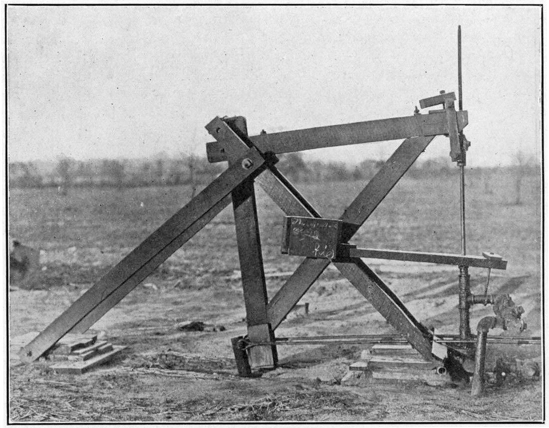
Plate X—B. The steel pumping jack. (Ill. Geol. Survey.)
Oil may be shipped to the refinery in tank cars, but at present little is transported in this way, because in most cases the production of a pool is sufficient to warrant the laying of a pipe line. The chief use for tank cars is in the transportation of the refined products from the refineries. The cars vary in capacity from 3,600 to 12,500 gallons. Many of the refineries own their tank cars, but in some cases they are leased.
Fire Protection
Where large quantities of oil are stored, either in the field or near refineries, there is always a danger from fire. This may be due either to artificial causes or to lightning. Proper insulation of the tanks is usually sufficient to safeguard them from danger of ignition by lightning, and proper rules for employees will usually control the danger from artificial causes. It is, however, possible to extinguish fires which have started in tanks or oil reservoirs by means of chemicals and apparatus which can now be installed easily. The general principle of such fire extinguishers is either to form a blanket of gas or foam over the burning liquid, which excludes the oxygen of the air, or to dilute the burning liquid with a non-inflammable agent, such as carbon tetrachloride, which extinguishes the flames. Some of the foam-producing mixtures have been particularly effective.
Refining of Petroleum
More or less successful refining of petroleum was in practice before the eighteenth century, but so great has been the advance in petroleum refining methods within the last few years that refineries seem to be only a recent development. The large number of refineries which have been completed within very recent years indicate the great importance of the. refining industry. The large number now in construction shows its continued rapid development.
Refining Methods
Most of the refineries in the Midcontinent field are equipped with apparatus for the production of naphtha, illuminating oils and fuel oils. Some of them are prepared to distill the residuals and produce lubricating oils, paraffin, and other products. The general procedure at the refineries is about as follows. Crude oil is admitted into the storage tanks along the pipe lines or received by rail from the tank cars. The oil is then run into the still and distilled by fire heat or by a combination of fire heat and superheated steam. The vapors from the still are carried into a condensing arrangement about which is a cold-water jacket, and the liquid product run into a tank. Many of the large refineries distill petroleum by the "continuous system," in which the stills are connected and operated in a continuous manner. By firing successive stills to higher temperatures, fractions with successively higher boiling. points are obtained simultaneously.
The chief methods of distillation are as follows: (a) The "dry" destructive or distillation "cracking" process, used when a large yield of gasoline and illuminating oil is desired; (b) fractional distillation; (c) vacuum process; (d) pressure distillation. [Note: For a complete account of petroleum refining methods, see Bacon and Hamor, American Petroleum Industry. vol. 2. 1916.]
(a) "Dry" or "cracking" distillation process. In this process the heavy vapors from the crude oil condense in the top of the still and fall back on the superheated oil, and are thus "cracked" or partially decomposed. The first of the products to form is naphtha or benzine. In the destructive distillation of a paraffin-base petroleum the flow begins at about 80° Baumé gravity, the product being termed "light naphtha." The next distillation is from 69° to 58° Baumé, and is known as "heavy naphtha." The third fraction, which is generally called the "high-test burning oil," is collected from 58° to 43° Baumé, The fourth fraction is known as "low-test burning oil" and is collected until the residue in the still reaches 21° or 22° Baume, Fractions 3 and 4 are usually redistilled in steam stills, and yield "burning-oil distillate" and "burning-oil stock." The residue is called tar, and contains the paraffin oil and paraffin wax. It is distilled to dryness, yielding "paraffin distillate" and "wax tailings," coke remaining behind. The proportion of the various products from this dry distillation is on the average as follows:
| Light and heavy naphtha (gasoline) | 12 to 15 percent |
| Burning-oil stock | 65 to 75 percent |
| Tar | 10 to 12 percent |
| Loss | 5 to 6 percent |
The temperatures at which the chief refinery products are derived in the "cracking" distillation of Kansas petroleum are as follows: When the temperature of the oil in the still is gradually raised from 200° F. to 325° F., about 6 to 8 percent of crude naphtha (boiling point 200° F.) is distilled. With a gradual increase from 325° to 475° F., 13 to 15 percent of the crude heavy naphtha is distilled; and to about 625° F. a "natural lamp distillate," representing 16 to 18 percent of the crude petroleum is obtained. The destructive distillation known as "cracking" begins at a temperature of about 625° F. The cracking is carried on very slowly, until at 700° F. a distillate called the "gas and fuel-oil stock" is produced. This contains some gasoline, lamp oil and heavier oils, and has an average boiling point of about 550° F. It comprises about 20 percent of the original crude petroleum. The residue left in the still at this temperature is a heavy black tar, about 42 percent of the crude oil.
(b) Fractional distillation. In the manufacture of lubricating oil from paraffin-base petroleum, "dry" steam is introduced into the oil. The hydrocarbons are then distilled at temperatures below their normal boiling points, because the partial pressure on the hydrocarbons is less than that of the atmosphere.
(c) Vacuum process. In some refineries a vacuum process is used in combination with (b). It consists in the creation of a partial vacuum in the still, so that the hydrocarbons are distilled at temperatures considerably below their boiling points at atmospheric pressure.
(d) Pressure distillation.-Several patented processes which involve pressure and high temperatures are now in use in the production of gasoline from gas and fuel oils. These "cracking" processes are too complex to be discussed here (Bacon and Hamor, op. cit., pp. 554-579.).
Petroleum Products Manufactured in the Midcontinent Field
Benzine. The raw condensate distilled from crude petroleum from the lightest fraction to about 52° Baumé gravity.
Gasoline. This includes many steam-refined products from the benzine. Three grades of gasoline are produced in Kansas and Oklahoma—68° to 70° Baumé, 64° to 66° Baumé, and 63° to 61° Baumé, The last two grades are those ordinarily used in automobiles.
Naphtha. The portion of steam-refined benzine of gravity heavier than gasoline, showing a gravity of 50° to 58° Baumé.
Kerosene. Including the heavier fractions, showing a gravity of 52° to 36° Baumé. These condensates are chemically treated with sulphuric acid and caustic soda. Several grades of kerosene and naphtha are manufactured by various refineries.
Fuel oil. This is an indefinite term, and there are no specifications for Midcontinent fuel oils. It must not contain gasoline, and many customers require that it be of such consistency that it can be pumped through pipes and burners.
Road oil. An indefinite name, covering grades of oil used chiefly as a dust preventive, ranging from 34° Baumé to an asphaltic material which is solid at 60° F. Several grades of road oil are produced from Kansas petroleum.
Lubricating oil. A great many grades of lubricating oil are produced at some of the refineries. Various companies have their own trade names for the different grades of these lubricating oils. In 1916 there were six refining companies in Kansas listed as producing lubricating oils.
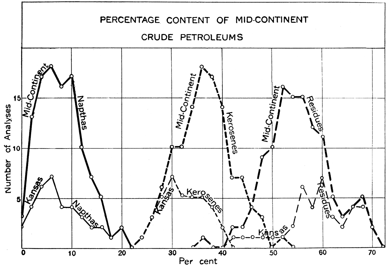
Figure 13—Average Midcontinent crude petroleum contains 5 to 10 percent naphtha, 34 to 40 percent kerosene, and 50 to 60 percent residues.
The refining of crude oil has undergone great changes during the past two years. Undoubtedly one of the chief factors has been the very rapidly increasing demand for gasoline. In 1915 average motor gasoline ranged from 60° to 64° Baumé. That generally used at this time has a distinctly lower gravity. Very little 60° to 61° gasoline is sold, the average being from 54° to 56°. This heavier fraction, formerly called naphtha, is now included as gasoline. It is realized, however, that degrees Baumé gravity do not necessarily indicate the quality of the gasoline or oil produced. It has been demonstrated that a 57° product may be just as good or better than a 60° product from another oil which has been treated in another manner.
[Note: An illustration of this is given by Mr. H. G. James, president of the Western Petroleum Refiners' Association (James, H. G., Refining Industry of the United States, Derrick Publishing Company, Oil City, Pa., 1916): "Taking a 400 gravity Cushing crude, a flrst-class 58° gravity gasoline is made by starting the initial at 125° F. and cutting the end point at 410° F. Now let us suppose the initial of this same treatment is 140° F., and the end point 460° F., you will secure a larger quantity but a far inferior product. In other words, a 58° gravity gasoline, as first described above, is a much superior article to a 60° or 61° with an initial of 130° F. and an end point of 435° F."]
Percentages of Gasoline Content
There is a marked difference in the gasoline content of various crude oils. The average yield of gasoline from Kansas crude in 1915 was about 12 percent. In 1916 oils from deep sands in Butler county produced an average of approximately 18 percent. The percentage of gasoline in the crude oil from the various producing districts of Kansas is as follows:
| Franklin and Miami counties | 8 to 13 percent |
| Montgomery county | 12 percent |
| Chautauqua county | 15 percent |
| Butler county (Augusta field) | 15 1/2 percent |
| Butler county (El Dorado field) | 22 1/2 percent |
A list of Kansas petroleum refineries has been compiled from latest available data and is included in the Appendix. There are a number of refineries under construction which are not contained in this list. [Note: For latest information consult some of the various oil magazines, such as the Oil and Gas News, Kansas City, Mo., or the Oil and Gas Journal, Tulsa, Okla. (Both published weekly.)]
Condensation of Gasoline from Natural Gas
[Johnson and Huntley, 1916, chapter XVII]
Mention of natural-gas gasoline is perhaps not out of place here, although it is as yet of comparatively little importance in this region.
Under a compression of 350 pounds, casing-head gas yields from one to four gallons of "wild" gasoline per 1,000 cubic feet of gas. In practice, commercial plants produce from one and one-half to three gallons. The gasoline produced is in many cases higher than 88° Baumé, but it is allowed to "weather" to this gravity before being shipped to a refinery for blending with low-grade naphtha.
A new process, in which gasoline is absorbed in oil, makes it possible to treat great quantities of gas rapidly. The oil, with its absorbed gasoline, circulates through a continuous still, in which gasoline is driven off and condenses separately, the oil going back to the absorbing apparatus.
The gas gasoline is sold to refineries to be blended with low-grade naphthas in the production of commercial grade gasoline, or is used in various chemical industries. Because of its very light, volatile character gas gasoline is very valuable in the production of highest-grade motor spirits for aeroplanes and other powerful gasoline engines.
Conditions Affecting Midcontinent Refineries
[Note: A detailed discussion of this subject will be found in Oil and Gas Journal, March 29, 1917.]
The refining situation in Kansas and Oklahoma remained unusually regular during 1916 and 1917. Prices fluctuated very little, and in the spring of 1917 there was probably less gasoline in storage than at the end of any previous winter in the history of the Midcontinent field. The congested condition of railroads prevented free movement of petroleum products and the glutting of the market. Nearly every refinery ran short of capacity and new refineries were held back for want of sufficient tank cars. Many projected refineries did not materialize at all, on account of inability to secure refinery equipment for prompt delivery, excessive cost of materials, and the high cost and nonprocurability of tank cars.
As a result, prices of refined products remained very satisfactory to the refiner. Gasoline fluctuated between 17 and 19 cents at the refinery for 60°, and between 15 and 17 1/2 cents for 58-59° gasoline. Kerosene received exceptionally high prices, going from 3 cents to as high as 7 cents, f.o.b. refinery. Because of the shortage of cars for transportation of coal, there was an unnatural demand for fuel oil, which soared to as high as $2.10 per barrel. The ability to run kerosene distillate into fuel oil and dispose of it at a high price caused the advance in that product. It was an unusual period, but on account of the high costs, profits were not greatly increased.
The investing public should scan carefully every refinery project as well as other oil ventures before placing their money. Some of the "mergers" and promotions of to-day are the worst sort of imposition, and people have invested in oil enterprises that can not possibly return them a dollar. So-called mergers are being effected and capitalized for millions that will never be heard of when the present unusual conditions are over. Unnatural profits never become the prevailing thing. Hundreds who look upon oil as a magic wealth producer will some day find that it is a business to be handled only in a businesslike way.
Prev Page--General Geology || Next Page--Stratigraphy
Kansas Geological Survey, Geology
Placed on web Aug. 10, 2018; originally published 1917.
Comments to webadmin@kgs.ku.edu
The URL for this page is http://www.kgs.ku.edu/Publications/Bulletins/3/06_prod.html