![]()
Prev Page--Geology || Next Page--Ground water chemical character, aquifer tests
Ground Water
Principles of Occurrence
The rocks and surficial deposits that form the crust of the earth are, in general, not solid throughout, but contain many open spaces, called voids or interstices, and it is in these spaces that water is found below the surface of the earth and from which it is recovered, in part, through springs and wells. There are many types of rocks and they differ greatly in the number, size, and arrangement of their interstices and therefore in their water-bearing properties. The occurrence of ground water in any region, therefore, is determined by the geology of that region.
The interstices of rocks range in size from pores of microscopic dimensions to openings several inches or feet in width. These interstices can be divided into two classes, primary interstices and secondary interstices. The primary or original interstices were formed during the formation of the rocks. Secondary interstices were developed by the different processes that affected the rocks after deposition. In Clay County all the water-bearing rocks are sedimentary, and the openings that bold the water are either open pore spaces between the grains of rock (primary interstices) or joints and open bedding planes, which have resulted from deformation of the rocks, and openings caused by solution of the rocks. These are secondary interstices.
The amount of water that can be stored in any rock depends upon the porosity of that rock. Porosity is expressed quantitatively as the percentage of the total volume of the rock that is occupied by interstices. When all the interstices in a rock are filled with water the rock is said to be saturated. The amount of water that a saturated rock will yield to the force of gravity is known as the specific yield. The amount of water that a rock can hold is determined by its porosity, but the rate at which it will yield water to wells is determined by its permeability. The permeability of a rock is its ability to transmit water under hydraulic gradient and is measured by the rate at which the rock will transmit water through a given cross section under a given loss of head per unit of distance. Some beds of clay or shale may have a high porosity, but because the interstices are small and poorly connected, they transmit little or no water, and the rock may be regarded as virtually impervious. Rocks differ greatly in their degree of permeability, according to the number, size, and interconnection of their interstices.
Source
Ground water is the part of the water below the surface of the earth that supplies wells and springs. In Clay County, ground water is derived entirely from precipitation, in the form of rain or snow, that falls directly on the county or on nearby areas. Part of the precipitation that falls as rain or snow is carried away by surface runoff and is discharged by streams, a part of it may evaporate, and a part may be absorbed by vegetation and transpired into the atmosphere. The part that escapes runoff, evaporation, and transpiration percolates slowly downward through the soil and underlying strata until it reaches the water table, where it joins the body of ground water in the zone of saturation. After reaching the ground-water body the water percolates slowly through the rocks in directions determined by the geology, topography, and geologic structure until it is discharged through wells and springs or by evaporation and transpiration in areas where the water table is shallow.
Artesian Conditions
Artesian conditions may exist where a water-bearing bed is overlain by a relatively impermeable bed that dips from its outcrop area toward the discharge area. Water entering the water-bearing bed in the outcrop area percolates downward to the water table and moves downdip beneath the confining bed. The weight of the water at higher levels in the confined bed creates a hydrostatic pressure in the water reservoir. When the confining bed is penetrated the water will rise in the drill hole to a level equal to the hydrostatic head of the aquifer at the point of discharge. If the pressure in the aquifer is sufficient to lift the column of water above the top of the aquifer, artesian conditions exist. If the pressure in the aquifer is sufficient to lift the water above the land surface, the well will flow naturally. Such a well is called a flowing artesian well. Well 8-4-21ac flowed when drilled, but as the flow continued only a few days, a pump was installed. A flowing well was observed a few hundred yards west of the Clay County line, in the NE sec. 13, T. 8 S., R. 1 W. Geologic and topographic conditions indicate that similar flowing wells could be drilled in an adjacent area in Clay County.
Although only one flowing well is known to have existed in the county, it is probable that artesian conditions exist locally over much of the county. In western Clay County the Dakota Formation contains lenticular sandstone bodies semiconfined beneath clay and shale, and much of the water is probably under some hydrostatic pressure. In eastern Clay County the rocks are a sequence of limestones and relatively impermeable shales. The limestones are in general the best aquifers, and local structures create hydrostatic head within the aquifers; although wells may not flow at the surface, in many of them the water rises above the aquifer.
The Water Table and Movement of Ground Water
The configuration and gradient of the water table and the direction of ground-water movement generally can be shown by constructing a water-table contour map. In Clay County, however, the water table is not everywhere continuous, so the water-table contours shown on Plate 2 cover only part of the areas discussed below. Clay County can be divided into three general areas on the basis of the occurrence and movement of ground water. The largest of these areas is that underlain by rocks of Permian age; it includes roughly the area east of a north-south line passing through the center of Range 2 East (Pl. 1). Although the largest, this area is probably the least important as a source of ground water, because it is underlain chiefly by shale. Water is derived principally from limestones but occurs also in appreciable quantity in solution channels in gypsum deposits in the lower shales of the Wellington Formation. The regional dip in this area is westward, and the water moves downdip from the recharge area that lies to the east.
The second largest ground-water area is that underlain by the Dakota Formation (Pl. 1). In this area water is obtained from sandstones in the lower part of the Dakota Formation. Water-table contours were drawn over a part of this area (Pl. 2), but in the areas where the Dakota Formation is thin it was not feasible to construct contours. Also, in many areas the water levels in the shallow wells did not fit the contour pattern of the water levels in deeper wells. The shallow water seemed to occupy a perched or semiperched position in relation to the rest of the Dakota Formation, and for this reason the shallow water levels were not used in constructing the water-table contours. The movement of ground water in this area is generally eastward toward the valley of Republican River.
The third and most important ground-water area in the county is the Republican River valley. Water is obtained from unconsolidated alluvial deposits, and large supplies are available for irrigation. The Republican River valley can be divided into two areas. One area is that part of the valley above Clay Center, where the Nolans Limestone crops out in the valley walls, and the second area is that part of the valley below the outcrop of the Nolans Limestone. In the upper area the valley is broad and flat and the contours cross the valley nearly at right angles to the river and valley walls, indicating that the river is neither gaining water from the ground-water reservoir nor losing water to it. The portion of the valley below the Nolans Limestone outcrop is narrower, and the water-table contours intersect the river at sharp angles, indicating that the river is draining the ground-water reservoir in this area.
Recharge
The addition of water to the zone of saturation is known as ground-water recharge. Ground-water recharge in Clay County occurs by infiltration from precipitation within the county, by percolation from influent streams, and by subsurface inflow from adjacent areas.
Recharge from Precipitation
The areas in Clay County that are most favorable to ground-water recharge are the small dune tracts near Clifton and Wakefield, where poor drainage and permeable soils tend to reduce runoff and induce infiltration. Next in importance is the valley area, which is relatively flat and is underlain by very permeable materials. Much water enters the ground-water reservoir in the outcrop area of the Dakota Formation where permeable sandstones are at or near the surface, although the steep, slopes of this area tend to encourage runoff.
Percolation from Outside the Area
Most of the recharge in the area underlain by the Permian rocks necessarily penetrates, through the more porous limestone beds in their outcrop areas and moves downdip to places where it is discharged. East of Clay County the lower part of the Barneston Limestone is cherty and fractured, and this area is probably the most important recharge area contributing water to the Permian rocks in Clay County.
Much water moves across the west county line of Clay County, through the Dakota Formation (Pl. 2). This water moves in a generally eastward direction to be discharged by seeps and springs and directly into the Republican River valley.
Seepage from Streams and Ponds
Much water is stored in ponds in Clay County. A large part of this water is lost through evaporation and transpiration and a part is used by livestock. The remainder seeps into the ground and becomes ground water. Under normal conditions the streams in Clay County contribute but little water to the ground-water reservoir, but when the stream stage is high a part of the water enters the, stream bank as "bank storage." This process may become an important source of recharge in the future if large-scale development of irrigation in the valley area lowers the water table in these deposits and permits infiltration from the streams.
Discharge
Ground water is discharged in Clay County by evaporation and transpiration, by seeps and springs, by wells, and by percolation to areas outside the county.
Discharge by Evaporation and Transpiration
In the areas in Clay County where the water table is only a few feet below the surface, water may be evaporated from storage. This is especially true in the valley of Republican River and to a lesser extent along the steeper slopes of the upland area where the water table is relatively near the surface and where seeps and springs occur. Transpiration accounts for much discharge in areas where the water table can be reached by the roots of plants.
Discharge by Seeps and Springs
The water-table contours (Pl. 2) indicate that ground water in the outcrop area of the Dakota Formation moves toward Republican River or its tributaries. Many springs and seeps occur along the valley walls and steep slopes adjacent to tributary streams, and a considerable quantity of water is discharged from storage by this means. Springs occur along the outcrop of the Permian limestones in eastern Clay County where structural conditions are favorable. This water has moved downdip from the recharge area farther east and is discharged in considerable quantity.
Discharge by Wells
Although large quantities of water are discharged through wells in Clay County, it is probable that the discharge of water by wells is small in comparison with discharge by other means. With increased development of irrigation, discharge by wells will become a more important factor.
Recovery
Principles of Recovery
When water is standing in a well the head of the water in the aquifer outside the well is in equilibrium with that in the well. When water is withdrawn from a well a difference in head is created between the water inside the well and the water outside the well for some distance from the well. The water table in the vicinity of the well develops a cone of influence (Fig. 5), which is deepest at the wall of the well and extends some distance around the well. An increase in the pumping rate of the well produces a greater drawdown.
Figure 5--Diagrammatic section of well that is being pumped, showing its drawdown, cone of depression, and radius of influence.
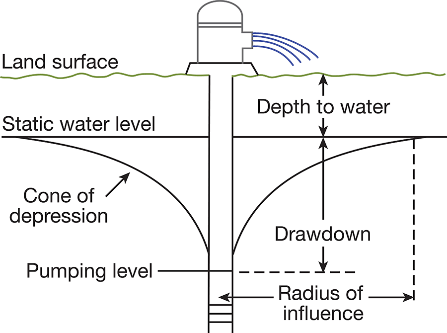
The specific capacity of a well is the rate of yield per unit of drawdown and is generally given in gallons a minute per foot of drawdown. Specific capacity is generally determined after the well has been pumped for a period long enough to stabilize the drawdown.
The character of the water-bearing material and the type of construction control the yield, drawdown, and specific capacity of a well. If the water-bearing material is coarse and well sorted it will readily yield large quantities of water to wells and have a minimum drawdown. If on the other hand the material is fine and poorly sorted, it will offer much resistance to the movement of water and thereby yield less water and have a greater drawdown. All other things being equal, the drawdown of a well varies inversely with the permeability of the water-bearing material.
Types of Wells
Several different types of wells are used in Clay County for the recovery of ground water. Wells generally are classed according to the method of construction. The particular type of well used at any location depends on the geology of the area, the depth to water and thickness of the saturated material at the location, and the use for which the well is constructed.
Dug wells--Dug wells are of large diameter, generally constructed with pick and shovel or other hand tools, and walled with stone, tile, or concrete. Such wells generally are constructed in areas where large supplies of ground water are not available, and the large hole is used as a storage reservoir, which provides water during periods of pumping and slowly fills when the pump is not running.
Driven wells--Driven wells are constructed by driving a pipe, generally 1 1/4 to 2 inches in diameter and equipped with a screen, to a point below the water table. Such wells are pumped with some type of shallow-well pump. Most driven wells are in valley areas, for they are limited to areas where the water table is not much below 20 feet and where the deposits are unconsolidated. This type of well also is generally used when only small supplies of water are required.
Drilled wells--Drilled wells are constructed by use of power-driven equipment to operate a percussion or rotary drill rig. This is the most common type of well in Clay County and is found in all types of material and in all localities. The depth of drilled wells is determined by the depth to the water table and the use for which the well is constructed. The use in turn may be limited by the quantity of water available. The diameter of drilled wells is generally dependent upon the use and desired quantity of water. Industrial, irrigation, and municipal wells require larger quantities of water and larger pumps and therefore require large-diameter holes to accommodate these pumps.
Utilization of Water
Ground water in Clay County is used chiefly for domestic, stock, and public supplies. Recent interest in irrigation in the valley areas in the county has caused an increase in the use of ground water for this purpose, and it is probable that there will be a considerable future increase. The quantity of water used for industrial purposes is small compared to that for other uses.
Domestic and Stock Supplies
Nearly all the domestic and stock supplies of water in rural areas and in small communities that do not have a public supply are obtained from privately owned wells. In the valley areas these supplies are obtained chiefly from drilled and driven wells. In the upland areas the water supplies are obtained from either dug or drilled wells. In several small areas underlain by shales of the Wellington Formation, there is a scarcity of wells and there are many abandoned farmsteads. A lack of dependable water supplies in these areas was a contributing factor in the abandoning of the farmsteads. In other areas the Wellington Formation yields water of good quality to wells.
Industrial Supplies
The quantity of water used for industrial purposes in Clay County is small in comparison with that for other uses. The Northern Natural Gas Company has four wells that yield water from terrace deposits in the Republican River valley in the NW sec. 1, T. 6 S., R. 1 E. The wells are 50 feet deep, are equipped with turbine pumps, and pump an average of 325,000 gallons of ground water a day for cooling. In Clay Center, Swift and Company uses water from a well (8-3-8bb1) for cooling. This well is about 65 feet deep, is equipped with a turbine pump having a capacity of 120 gpm, and is pumped at an average rate of about 170,000 gpd. Well 8-3-8bc is owned by the Clay Center Coca Cola Bottling Company. This well is equipped with a jet pump having a capacity of about 50 gpm. The water is softened and the iron is removed. The average daily use is about 1,500 gallons.
Public Supplies
Seven cities in Clay County have public water supplies. These supplies are discussed in the following paragraphs.
Clay Center--The Clay Center water supply is obtained from five wells drilled in the low terrace deposits in the Republican River valley. Three of these wells in Utility Park are 55 feet deep and the depth to water is about 22 feet. Well 8-3-8bb4 was tested for 8 hours at a rate of 850 gpm, and had a drawdown of 14 feet. Well 8-3-8bd in Dexter Park, which was drilled in the summer of 1954, yields water from terrace gravels. The well is 60 feet deep and the depth to water is about 29 feet. After the well was pumped 8 hours at a rate of 500 gpm, the drawdown was 4 feet. Well 8-3-8db, in the southeastern part of Clay Center, is a drilled well 58 feet deep and yields water from terrace gravels. In August 1954 the depth to water was 28 feet. All the wells are equipped with electric turbine pumps. The maximum capacity of the five wells is about 4 million gallons per day, and the average daily use is about 800,000 gallons. The water is chlorinated but receives no other treatment. The water is stored in an elevated steel tank having a capacity of 500,000 gallons. In addition to the five wells used for the public water supply, the city has four wells at the municipal power plant that provide water for cooling. These are drilled wells about 50 feet deep equipped with turbine pumps. The average daily pumpage from these wells is 1.7 million gallons.
Clifton--The Clifton water supply is obtained from two wells (6-1-2bac1 and 6-1-2bac2) in the southwestern part of the city. The wells, which are equipped with turbine pumps, yield water from terrace deposits in the Republican River valley and are about 65 feet deep. The water level in August 1954 was about 30 feet. The drawdown in each of these wells is 7 feet at a pumping rate of 160 gpm. The maximum capacity of the two wells is about 360,000 gallons per day and the average daily use is 100,000 gallons. Hardness is reduced by pressure zeolite softeners and the water is chlorinated. A steel standpipe has a capacity of 90,000 gallons.
Green--The Green municipal water supply is obtained from two wells (7-4-20ad and 7-4-21bc), which yield water from the Fort Riley Limestone member of the Barneston Limestone at depths of 170 and 190 feet respectively. The water is hard but receives no treatment. The capacity of the wells is about 30,000 gpd, and the average daily use is about 10,000 gallons. Water is pumped directly to an elevated concrete storage tank having a capacity of 60,000 gallons.
Idana--The Idana water supply is obtained from one well (8-1-13ca) south of town in a creek valley. It yields water from terrace deposits along the edge of the valley. Average use at Idana is about 5,300 gpd. Storage capacity is 10,000 gallons in an underground steel tank.
Longford--The Longford municipal water supply is obtained from two wells about half a mile west of the city. These wells (10-1-17dc1 and 10-1-17dc2) yield water from the Dakota Formation. The wells are 100 and 110 feet deep, respectively. The average daily pumpage is about 15,000 gallons. The water is chlorinated and delivered to the mains from an elevated concrete tank having a capacity of 60,000 gallons.
Morganville--The Morganville water supply is obtained from two wells within the city limits. These wells (7-2-3cc and 7-2-4ddc) obtain water from terrace deposits in the Republican River valley. The wells are 53 and 57 feet deep, respectively, and are equipped with turbine pumps. Maximum daily yield is 160,000 gallons, and average daily pumpage is 30,000 gallons. The water is chlorinated and delivered to the mains from an elevated steel tank having a capacity of 50,000 gallons.
Wakefield--The Wakefield water supply is obtained from two wells at the south edge of the city. These wells (10-4-5db1 and 10-4-5db2) obtain water from terrace deposits in the Republican River valley. The wells are 57 feet deep and are equipped with turbine pumps. The water levels in the wells were 34 feet below the surface in August 1954. After the wells are pumped for 24 hours at the rate of 100 gpm each, the drawdown is 2 feet. The yield of the wells as equipped is about 300,000 gpd, and average daily use is 80,000 gallons. The water is chlorinated and delivered to the mains from an elevated steel tank having a capacity of 30,000 gallons.
Irrigation Supplies
In the fall of 1954 six irrigation wells having a combined capacity of about 5,000 gpm were in operation in Clay County. Continued drought conditions during the growing season in 1955 intensified interest in irrigation, and by autumn 29 additional wells had been drilled, which had a combined capacity of about 21,000 gpm. In 1955 about 2,730 acre-feet of water was pumped for irrigation.
Four of the irrigation wells drilled in 1955 obtain water from the Barneston Limestone. The yields of these wells range from about 50 to 250 gpm. The other 25 wells obtain water from alluvial materials in the valley area. The yields of these wells range from 350 to 2,000 gpm.
Maps were prepared showing the configuration of the bedrock surface in the valley area (Fig. 6) and the water-table contours (Pl. 2). The water-table map was superposed over the bedrock map and a saturated-thickness map was prepared by connecting the points of equal thickness (Fig. 7). The bedrock contour map (Fig. 6) indicates that the pre-Pleistocene surface of the valley above Clay Center was a broad V-shaped valley in which the deeper part generally is near the center of the valley. Below Clay Center, where the limestones of Permian age cross the valley, the valley is also V shaped but is much narrower. The saturated-thickness map (Fig. 7) indicates that the thickest deposits of saturated material follow the deepest channels of the pre-Pleistocene surface shown in Figure 6, and the greatest thickness is in the northwest corner of the county, where the saturated materials are 80 feet thick. The thickness of these materials gradually decreases downstream to a point just west of Clay Center where the saturated material is only 40 feet thick, and below a point a short distance downstream from Clay Center the thickness of saturated materials is about 20 feet except in a very narrow channel cut in the pre-Pleistocene surface. The volume of saturated material in the valley area was determined from Figure 7, and by applying a specific yield of 20 percent the volume of water in storage was calculated. The volume of saturated material and volume of water in storage are given by townships in Table 2. Table 2 indicates that about 275,000 acre-feet of water is in storage west of the west line of Range 3 East and only about 45,000 acre-feet east of this line. The large amount of storage upstream from Clay Center in comparison with the small amount downstream is due to the great amount of alluvium upstream; the valley becomes narrower and shallower downstream because it is cut in the more resistant Permian limestones that cross the valley downstream, whereas upstream the less resistant Wellington and Dakota Formations form the bedrock underlying the valley area. The amount of water in storage (320,000 acre-feet) is equal to the quantity of water that would be pumped in 60 to 65 years at the 1955 rate of withdrawal for industrial and municipal use, which is about 5,000 acre-feet per year. This does not take into consideration any recharge to the valley during that period. The water-table contours indicate that water moves into the valley area, and although no quantitative data are available a considerable quantity of water must be contributed to the valley area in this way. Surface water is contributed to the valley through local drainage and through Republican River. Recent completion of reservoirs on Republican River in Colorado and Nebraska will aid in maintaining a minimum flow in the river. There seems to be no immediate danger of a serious depletion of ground water in storage in the Republican Valley, but a continued increase in the irrigation development will cause a lowering of the water table in the area and may diminish the streamflow during periods of heavy pumping.
Figure 6--Configuration of bedrock surface in Republican River valley.
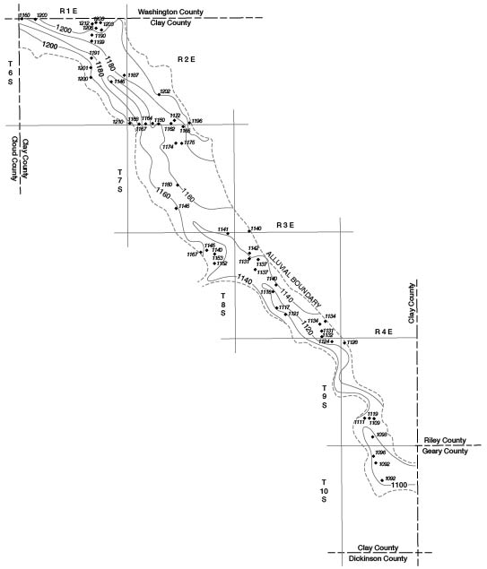
Figure 7--Thickness of saturated material in Republican River valley.
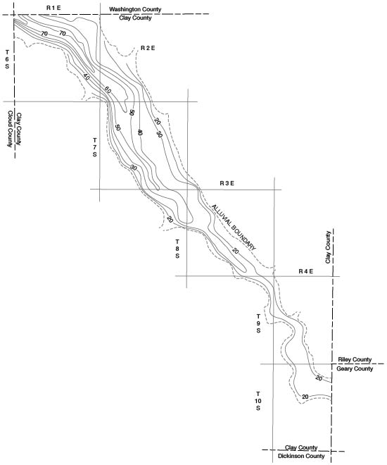
Table 2--Volume of saturated water-bearing material in Republican River valley and volume of water in storage based on specific yield of 20 percent.
| Township | Acre-feet of saturated material |
Acre-feet of water in storage |
|---|---|---|
| T. 6 S., R. 1 E. | 560,000 | 110,000 |
| T. 6 S., R. 2 E. | 240,000 | 49,000 |
| T. 7 S., R. 2 E. | 510,000 | 100,000 |
| T. 7 S., R. 3 E. | 7,000 | 1,400 |
| T. 8 S., R. 2 E. | 100,000 | 20,000 |
| T. 8 S., R. 3 E. | 140,100 | 29,000 |
| T. 9 S., R. 3 E. | 13,000 | 2,600 |
| T. 9 S., R. 4 E. | 39,000 | 7,800 |
| T. 10 S., R. 4 E. | 32,000 | 6,400 |
| Total | 1,600,000 | 320,000 |
Prev Page--Geology || Next Page--Ground water chemical character, aquifer tests
Kansas Geological Survey, Geology
Placed on web April 7, 2009; originally published June 1959.
Comments to webadmin@kgs.ku.edu
The URL for this page is http://www.kgs.ku.edu/General/Geology/Clay/05_gw.html