![]()
Prev Page--Ground water occurrence, water table || Next Page--Utilization, chemical quality
Ground Water, continued
Ground-water Recharge
Recharge is the addition of water to the ground-water reservoir and may be accomplished in several ways. All ground water available to wells in Wichita and Greeley counties is derived from precipitation falling as rain or snow within the area or in near-by areas to the west and north. Part of the water that falls as precipitation is carried away by surface runoff, part evaporates, and some is absorbed by plants and returned to the atmosphere as water vapor by the process known as transpiration. Water that escapes runoff, evaporation, and transpiration percolates slowly down through the soil and underlying strata, and eventually reaches the zone of saturation.
The quantity of water that is carried away by surface runoff depends upon several factors: the intensity of the rainfall, the slope of the land, the type of soil, the kind and amount of vegetation, and the time of year.
More of the rainfall enters the ground during a long gentle rain than during a torrential downpour, when the percentage of runoff is large. The slope of the land is an important factor in determining runoff; the steeper the slope, the greater will be the amount of runoff. In general, runoff is greater in tightly compacted, fine-grained soil than in loose, sandy soil. Runoff is greater in winter when frozen ground prevents infiltration. A suitable vegetative cover will reduce the velocity of surface runoff and afford a better opportunity for water to seep into the soil.
The amount of water from precipitation that is lost by runoff in the Wichita-Greeley area is very small. Although rains are usually torrential and the soil is only moderately permeable, most of the slopes are gentle to moderate and much of the area is poorly drained. According to Fishel (1952, p. 58) the annual runoff in Pawnee Valley in Ness and Hodgeman counties, where the average annual precipitation is about 22 inches, is only 0.3 inch. In Cheyenne County, Kansas, the runoff from the area drained by South Fork Republican River is 0.68 inch (Prescott, 1953, p. 33). The runoff in the Wichita-Greeley area is probably less than the runoff in either the Pawnee Valley or the valley of South Fork Republican River in Cheyenne County.
Most of the water that reaches the land surface as precipitation never reaches the water table, however, because it is lost by evaporation and transpiration at the surface. A large percentage of the precipitation falls during the period from April through September when the temperature is high, the humidity is low, the wind movement is large, and, consequently, the rate of evaporation is high. According to the 32-year record at the Tribune Experiment Station, the average rate of evaporation from a free water surface during the months of the growing season is: April, 7.04 inches; May, 9.13 inches; June, 11.05 inches; July, 12.85 inches; August, 11.38 inches; and September, 8.56 inches (U. S. Weather Bureau, 1950, p. 4). The opportunity for evaporation greatly exceeds the amount of precipitation and thus much of the annual precipitation in the area is lost by evaporation.
During the growing season the amount of water absorbed by plants and transpired to the atmosphere as water vapor is large. The quantity of water lost by transpiration varies widely with different species of plants. The use of water by plants can be shown by stating the quantity of water consumed to produce a unit weight of plant matter. This quantity is designated the transpiration ratio. The transpiration ratios, in pounds of water per pound of dry matter, for a number of plants common in the Wichita-Greeley area are: wheat, 375; alfalfa, 829; buffalo grass, 308; and sunflower, 577 (Foster, 1948, p. 286).
The water that escapes runoff, evaporation, and transpiration percolates through the soil zone into the unsaturated material above the water table. When it reaches an amount greater than can be held by the capillary force opposing the pull of gravity, the excess water moves to the saturated zone. Such recharge is slight during the growing season. During the fall and winter, however, when evaporation and transpiration are at a minimum, recharge to the water table may be substantial if precipitation is sufficient and soil conditions are favorable.
Although the normal annual precipitation in Wichita and Greeley counties is from 16 to 17 inches, probably only about one-tenth of an inch, or about 2.7 billion gallons, reaches the water table in the average year.
Streams
One of the principal sources of ground-water recharge in Wichita and Greeley counties is the water lost from streams. With the exception of the eastern part of Ladder Creek in Wichita County, all streams in the area flow only after periods of heavy rainfall. The alluvium in the valleys of White Woman, Ladder, and Sand Creeks is rather permeable and during periods of stream flow much water probably percolates down through the alluvium and reaches the body of ground water.
In August 1948 Branch observed the advance of water in the dry bed of White Woman Creek in the NW sec. 23, T. 18 S., R. 38 W approximately 26 miles from the Scott County line, after a storm that had occurred about 12 hours previously in the headwater area. As the water advanced, part of it sank immediately into the alluvial sand and gravel, resulting in the continuous displacement of air bubbles from the alluvium. The flow of water, which was about a foot deep, did not reach the Scott County line. It is probable that much of this water recharged the ground-water body.
Subsurface Movement From Adjacent Areas
The water-table contour lines on Plate 1 indicate that ground water moves into the Wichita-Greeley area from the west and northwest. Calculations using Darcy's law for the movement of ground water indicate that approximately 1.8 billion gallons of water is added annually to the available supply of ground water by subsurface inflow. This represents a large part of the total annual recharge to the ground-water reservoir in Wichita and Greeley counties.
Irrigation Water
In areas that are irrigated extensively, ground-water recharge occurs by seepage from ditches and by downward percolation after the water has been spread on the fields. Probably very little recharge is derived from irrigation water in Wichita and Greeley counties because of the rather impermeable loess cover, which retards downward seepage of water and thus increases the opportunity for evaporation and transpiration.
Ground-water Discharge
Meinzer (1923a, p. 48) divided the discharge of subsurface water into vadose-water discharge, which is discharge of soil water not derived from the zone of saturation, and ground-water discharge or discharge from the saturated zone. Ground-water discharge takes place through evaporation and transpiration, through wells and springs, by seepage into streams, and by underground movement to adjacent areas.
Transpiration and Evaporation
Water may be taken into the roots of plants directly from the zone of saturation and may be discharged from the plants by transpiration. The depth to which the roots of plants go for water varies with different kinds of plants and types of soil. Ordinary plants and grasses do not draw water from depths of more than a few feet, but alfalfa may obtain water from 20 or 30 feet below the surface--more, in places, and certain desert plants have been known to send their roots 50 or 60 feet to reach the water table (Meinzer, 1923, pp. 82-83).
In most of Wichita and Greeley counties the water level is considerably below the root tips of plants. However, in certain areas along White Woman, Ladder, and Sand Creeks (Pl. 2) the water table is not far below the surface of the ground and plants may draw water directly from the ground-water body. Direct evaporation from the water table also is restricted to these areas.
Springs and Seeps
The amount of water discharged from springs in Wichita and Greeley counties is negligible. During the course of the investigation the only spring observed was along Ladder Creek in the SW NE sec. 23, T. 17 S., R. 37 W. However, it is probable that there are other springs on Ladder Creek between this point and the Scott County line.
Discharge by seepage into streams in Wichita and Greeley counties is also negligible and is restricted to the eastern reach of Ladder Creek in Wichita County. This part of Ladder Creek is generally in equilibrium but at times receives water from the ground-water reservoir and at other times gives water to it. Its western reaches in western Wichita County and in Greeley County and White Woman and Sand Creeks lie entirely above the water table and therefore receive no water from the ground-water body.
Wells
The discharge of water from wells is one of the most important methods of ground-water discharge in Wichita and Greeley counties. Large amounts of water are pumped from irrigation wells in addition to that from public-supply, domestic, and stock wells. It is estimated that more than 2 billion gallons a year is pumped from wells, although this figure may vary considerably with precipitation, which affects the amount of water needed for irrigation.
Subsurface Movement to Adjacent Areas
As indicated by the water-table contour lines (Pl. 1), ground water leaves the area by subsurface flow, principally to the east. It is thought that this constitutes the principal means of ground-water discharge in the Wichita-Greeley area. Roughly 2.5 billion gallons of water leaves the area annually by this method. This outflow contributes a considerable amount of the water that is pumped for irrigation in Scott County.
Recovery of Ground Water
Principles of Recovery
When water is standing in a well there is equilibrium between the pressure of water within the well and the pressure of the water outside the well. When water is pumped from a well the pressure inside the well is reduced and water moves into the well from the surrounding aquifer. When water is being discharged from a well the water table in the vicinity of the well is lowered to form a depression somewhat resembling an inverted cone. This depression of the water table is known as the cone of depression and the distance that the water level is lowered at the well is called the drawdown (Fig. 11). The greater the pumping rate in a well, the greater is the drawdown. When pumping stops, the cone gradually fills with water from adjacent areas until equilibrium is again reached.
Fig. 11--Diagrammatic section of a pumping well showing drawdown, cone of depression, and radius of influence.
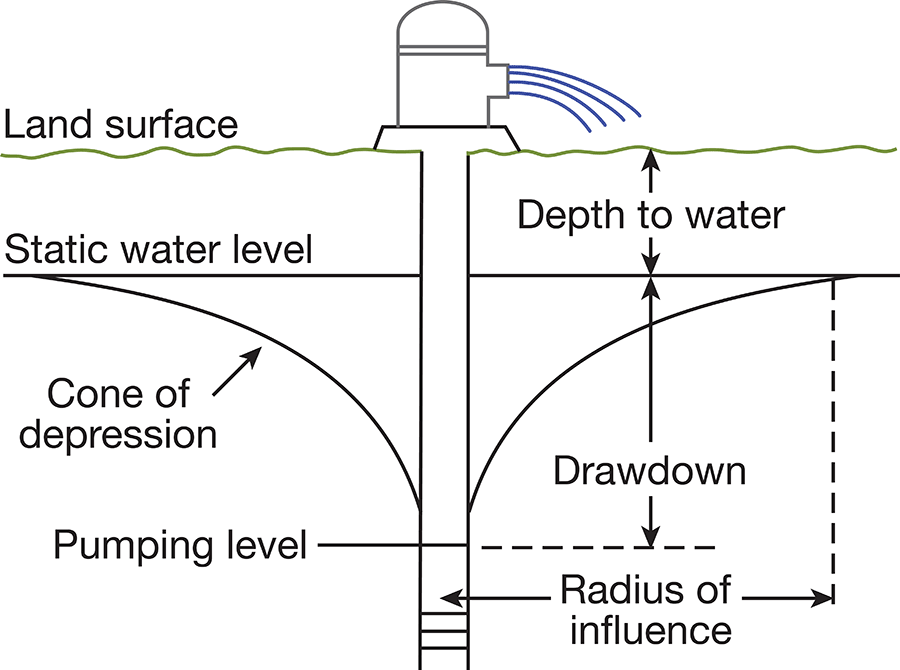
The capacity of a well can be defined as the maximum rate at which it will yield water after the pumping water level becomes approximately stabilized. The capacity depends on the quantity of water available, the thickness and permeability of the aquifer, and the construction and condition of the well itself. The capacity of a well is generally expressed in gallons a minute. The specific capacity of a well is its rate of yield per unit of drawdown and is determined by dividing the capacity in gallons a minute by the drawdown in feet.
When a well is pumped the water level drops rapidly at first, then more slowly, and it may continue to decline for several hours or days. When pumping ceases the water level rises rapidly at first, then more slowly, and it may continue to rise long after pumping has stopped.
Dug Wells
Dug wells are wells that have been excavated, usually with pick and shovel. Because of their large diameter, generally 3 to 4 feet, they have a large storage capacity. Those in Wichita and Greeley counties are cased with rock, iron, steel, or concrete, or are uncased. There are very few dug wells in these two counties, however, and most of these are in rather poor water-bearing material, in areas where the ground-water supply is not plentiful.
Driven Wells
Driven wells are generally constructed by driving a 1 1/4- to 1 1/2-inch pipe (equipped at the bottom with a screened drive point) below the water table. Included in the well inventory is only one of this type, well 20-37-13add, which is a stock well located in a small draw in southern Wichita County. This well was dug to about 16 feet, slightly below the water table, and a sand point is reported to have been driven from that depth to 24 feet in unconsolidated sand of the Ogallala formation.
Drilled Wells
Most of the wells in Wichita and Greeley counties have been drilled by either a cable-tool or a hydraulic-rotary drill. The cable-tool method has been used in the drilling of most of the domestic and stock wells and the hydraulic-rotary method in drilling most of the large-diameter wells such as irrigation and public-supply wells. In the cable-tool or percussion method, a portable cable-tool drill mounted on a truck or trailer is used. Drilling is done by the alternate lifting and dropping of a heavy bit to produce a cutting action at the bottom of the hole. The crushed material in the hole is mixed with water added during the drilling and removed by a bailer or sand bucket. In the hydraulic-rotary method a hollow drill stem equipped with a cutting bit is rotated in the hole and cuttings are removed by circulating muddy water under high pressure down through the stem and up through the annular space between the drill stem and the hole. The cuttings are brought to the surface as fragments suspended in the mud. The mud serves also to plaster the walls of the hole, thereby preventing caving until casing is installed. In the reverse-rotary method, which is sometimes employed in the drilling of large-diameter wells, the direction of flow of water is reversed, and cuttings are carried up through the drill stem and discharged into a pit at the surface.
Most of the drilled wells in Wichita and Greeley counties obtain water from unconsolidated or only partly consolidated deposits of the Ogallala formation. Wells in these deposits are generally cased to the bottom, to prevent caving of the walls, with galvanized iron, steel, or iron casing. In some wells the water may enter only through the open end of the casing, but in most wells the casing below the water table is perforated or a well screen is used to increase the intake area. The selection of the proper size of perforations is important in the construction of a well and may determine the capacity and life of a well. If the perforations are too large, fine material may filter through and fill the well; if the perforations are too small they may become clogged and prevent the free entrance of water. Commonly a slot size that will pass from 30 to 60 percent, by size, of the water-bearing material is selected. The coarser particles remaining around the screen form a natural gravel packing, which increases the effective diameter and therefore the capacity of the well.
Many of the wells of large diameter, such as municipal and irrigation wells, that have been drilled in the last several years are gravel packed. In constructing a well of this type in the Wichita-Greeley area, a hole of large diameter (about 30 inches) is first drilled and temporarily cased with blank casing. A well screen or perforated casing is centered opposite the water-bearing beds and enough unperforated casing, generally 16 to 18 inches in diameter, to reach the surface is added. The space between the two casings is filled with sorted gravel of a grain size slightly larger than the openings in the screen or perforated casing, and also slightly larger than that of the water-bearing material. The outer casing is then withdrawn to uncover the screen and to allow the flow of water from the water-bearing material through the gravel packing. The envelope of well-sorted gravel that surrounds the well increases the effective diameter of the well and decreases the velocity of water leaving the formation. This reduction in velocity reduces the movement of fine sand into the well. The friction of water entering the well is reduced and the drawdown and consequently the cost of pumping are reduced. If the water-bearing formation contains sufficient coarse material, the addition of a gravel pack around the screen may not increase the yield of a well appreciably.
For more details on the drilling and development of wells the reader is referred to reports by Bennison (1947), Rohwer (1940), and Davison (1939).
Methods of Lifts and Types of Pumps
Most domestic and stock wells in Wichita and Greeley counties are equipped with cylinder pumps which are operated by windmills, electricity, or gasoline engines, or in a few cases by hand. Most of the cylinder pumps have the cylinder or working barrel below the water level and are of the lift type which discharges water at the surface or to near-by elevated storage tanks. A few wells are equipped with jet pumps, which use a stream of water under pressure to raise the water.
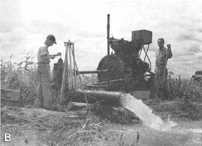
Most of the irrigation wells in the area are equipped with vertical turbine pumps operated by gasoline, diesel-fuel, or butane-gas engines or by electricity (Pl. 6b). One irrigation well inventoried is equipped with a vertical centrifugal pump. The municipal wells at Leoti, Tribune, and Horace have vertical turbines powered by electricity.
Plate 6B--Irrigation well 18-35-34abb, owned by D. J. Hutchins, being pumped at 2,100 gallons a minute.
Prev Page--Ground water occurrence, water table || Next Page--Utilization, chemical quality
Kansas Geological Survey, Geology
Placed on web Jan. 11, 2008; originally published April, 1954.
Comments to webadmin@kgs.ku.edu
The URL for this page is http://www.kgs.ku.edu/General/Geology/Wichita/05_gw2.html