![]()
Prev Page--Ground Water Principles, Water Table || Next Page--Utilization
Ground Water, Continued
Ground-water Recharge
Recharge is the addition of water to the underground reservoir and may be accomplished in several ways. All ground water within a practical drilling depth beneath Seward County is derived from water that falls as rain or snow either within the area or within nearby areas to the west and north. Once the water becomes a part of the groundwater body it moves down the slope of the water table, later to be discharged farther downstream.
The underground reservoir beneath Seward County is recharged primarily by local precipitation. Other factors affecting recharge in this area are seepage from streams and depressions and sub-surface inflow from areas to the west and north.
Recharge from Precipitation
The average annual precipitation in Seward County is about 19 inches, but only a part of this water reaches the zone of saturation owing to evaporation, transpiration, and surface runoff. The amount of water added to or discharged from the groundwater reservoir is reflected in the fluctuations of the water levels in wells. Periodic measurements of water levels in wells 23, 53, 56, 64, and 158 have been made since August 1940. The fluctuations of the water levels in these wells are shown in Figure 7. Well 53 is a shallow well in Cimarron Valley whereas the other wells are on the upland and have depths to water level ranging from about 96 feet to more than 209 feet. The water levels in all of the observation wells in Seward County were higher at the end of 1944 than they were at the beginning of record. The water level in most wells rose during 1941, 1942, and 1944 which were years of above-normal precipitation, whereas the water level in most wells declined during 1943, a year of below-normal precipitation.
Figure 7--Hydrographs showing the fluctuations of the water levels in five wells in Seward County, the cumulative departure from normal monthly precipitation at Liberal, and the monthly precipitation at Liberal. A larger version of this figure is available.
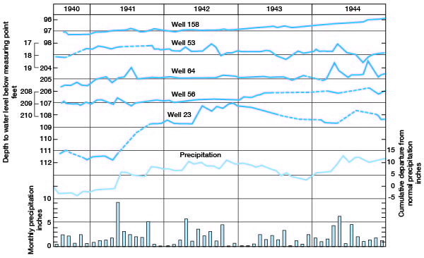
The fact that the water level in some deep wells fluctuates only slightly does not necessarily mean that there is no recharge, for the water level will rise only when the rate of recharge exceeds the rate of groundwater discharge. The recharge in such areas probably is more or less continuous and is about equal to the natural discharge. Although the annual net rise in water levels in the four deep wells is small, the cumulative rise may be relatively large. The average cumulative rise of water levels in these wells ranged from 0.48 foot in 1943 to 2.00 feet in 1944.
From the beginning of 1941 to the end of 1944 the water levels in three upland wells (56, 64, and 158) rose an average of 0.22 foot a year. If the specific yield of the upper part of the zone of saturation in this area were known, the amount of the annual gain in storage of ground water could be estimated. If it were assumed that the specific yield is 15 percent, then the annual gain in storage would amount to about 0.4 inch and the gain in storage for the four years (1941-1944) would amount to about 1.6 inches. A gain in groundwater storage of 1.6 inches would amount to about 83 acre-feet (27,000,000 gallons) per square mile.
Recharge from Seepage
Some water is contributed to the ground water reservoir by seepage from streams and depressions. Cimarron River is a losing stream in the northwestern part of Seward County. In this part of the course of the Cimarron some of the flood water moves downward to the zone of saturation. This has caused a mound on the water table near the northwest corner of the county (Pl. 1).
Well 23 is located about 0.5 mile from the flood plain of Cimarron River. During a flood in 1941 the floodwater extended from bluff to bluff. It is believed that seepage during this and subsequent floods produced much of the rise shown for well 23 in Figure 7.
Recharge by Subsurface Inflow
Ground water moves into Seward County by subsurface inflow from Stevens County on the west and Haskell County on the north. The water moves across the county in a general southeasterly direction into Meade County, Kansas, and Texas and Beaver Counties, Oklahoma.
Discharge of Subsurface Water
Ground water discharge is the discharge of water directly from the zone of saturation or from the capillary fringe, and may take place through evaporation and transpiration or as hydraulic discharge through springs, seeps, wells, and infiltration galleries.
Discharge by Transpiration and Evaporation
Water may be taken into the roots of plants directly from the zone of saturation or from the capillary fringe, and discharged from the plants by the process known as transpiration. In most of Seward County the depth to the water table is so great that there is no transpiration or evaporation from the zone of saturation or from the capillary fringe. In Cimarron Valley, however, the water table is shallow and much ground water is discharged by these processes.
Discharge by Springs and Seeps
A relatively small amount of ground water is discharged by springs in Seward County. The only spring noted in the county was in the S 1/2 sec. 6, T. 33 S., R. 32 W. Residents reported that there were formerly several springs in that vicinity. The water from the spring is ponded in a small tributary to Cimarron River by a small dam. The water seemingly does not flow from the principal zone of saturation but from a perched body of water overlying a relatively impermeable mortar bed. A similar spring was observed in Wolf Canyon in Meade County a few yards east of the E. line sec. 12, T. 35 S., R. 31 W. The water there also is flowing from a perched body of water.
The seepage of water into Cimarron River is one of the principal processes of discharge of ground water in Seward County. In most of Seward County the channel of Cimarron River is lower than the level of the water table in the adjacent upland areas; hence the groundwater moves toward the river and discharges into the stream channel. Toward the southeast the rate of discharge increases because the difference between the altitude of the stream channel and the altitude of the water table in adjacent areas increases.
Discharge by Subsurface Flow
Much ground water is discharged from this area by subsurface flow into adjacent areas toward the east and south. This is indicated by the slope of the water table (Pl. 1), which indicates that the water moves into Meade County and into Texas and Beaver Counties, Oklahoma.
Discharge by Wells
Another method of discharge of water from the groundwater reservoir is the discharge of water from wells. All domestic, industrial, railroad, and municipal supplies of water and much of the livestock supply of water in Seward County are derived from wells. The amount of water discharged from wells for these purposes, however, is relatively small. The recovery of ground water from wells is discussed in the next section.
Recovery
Principles of Recovery
The discharge from a well is produced by a pump or some other lifting device or by artesian head (for a more detailed discussion of the principles of recovery, see Meinzer, 1923a, pp. 60-68). When water is being discharged from a well there is a resulting drawdown or lowering of the water level, or, in a flowing artesian well, an equivalent reduction in artesian head. The water table is lowered in an area around the well to form a depression resembling an inverted cone. This depression of the water table is known as the cone of depression, and the distance that the water level is lowered at the well is called the drawdown. In any well, the greater the rate of pumping, the greater will be the drawdown.
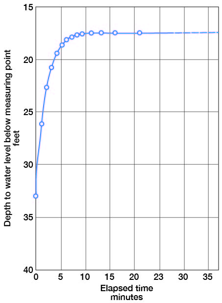
When water is withdrawn from a well, the water level declines rapidly at first and then more slowly until it finally becomes nearly stationary. Conversely, when the withdrawal ceases, the water level rises rapidly at first and then more slowly until it eventually resumes its original position (Fig. 8).
Figure 8--Graph showing the recovery of water level in well 53. (Measurements by Woodrow W. Wilson.)
Construction of Wells
All but one of the wells listed in Table 10 are drilled wells. Well 22 consists of a battery of two dug wells used to supply water for irrigation. One driven well was observed during the course of the investigation but it could not be measured.
Drilled wells are excavated by means of a percussion or rotary drill. They generally are 4 to 6 inches in diameter although the railroad, industrial, and municipal wells may be much larger. The domestic and stock wells generally are cased with galvanized-iron casing but a few are cased with wrought-iron casing. Most of the large-diameter wells are cased with wrought iron.
Almost all wells in Seward County obtain water from unconsolidated deposits, principally the Rexroad (?) and Meade formations. Wells in these deposits generally are cased to the bottom of the hole to prevent caving. In most of the domestic and stock wells the water enters only through the open end of the casing but in the larger wells the casing generally is perforated below the water table to provide greater intake facilities. The size of the perforations is an important factor in the construction of a well and the capacity or even the life of the well may be determined by it. If the perforations are too large fine material may filter through and fill in the well; if the perforations are too small they may become clogged so that water is prevented from entering the well freely.
Some wells in unconsolidated sediments are equipped with well screens or strainers. It is common practice to select a slot size that will pass 30 to 60 percent of the water-bearing material, depending upon the texture and degree of assortment. Retention of the coarser particles around the screen forms a natural gravel packing that greatly increases the effective diameter of the well, thereby increasing its capacity.
Gravel-wall wells generally are effective for obtaining large supplies of water from relatively fine-grained unconsolidated deposits and are widely used for irrigation in the upland areas of western Kansas. In constructing a well of this type, a hole of large diameter, 30 to 60 inches, is drilled and is temporarily cased with unperforated pipe. A well screen or perforated casing of smaller diameter than the hole is then lowered into place and centered in the larger pipe opposite the water-bearing beds. Unperforated casing extends from the screen to the surface. The annular space between the inner and outer casings is then filled with sorted gravel. The outer casing is then withdrawn part way to uncover the screen and allow the gravel packing to come in contact with the water-bearing material.
According to McCall and Davison (1939, p. 29), drawdown can be kept to a minimum in several ways:
First, the well should be put down through all valuable water-bearing material. Secondly, the casing should be properly perforated so as to admit water to the well as rapidly as the surrounding gravel will yield the water, Third, the well should be completely developed so that the water will flow freely into the well ... Increasing the depth of a well will have a greater effect on reducing the draw-down than will increasing the diameter, so long as additional water-bearing formations are encountered.
A report (Davison, 1939) containing descriptions of different types of pumping plants, the conditions for which each is best suited, construction methods, and a discussion of cost of construction is available from the Division of Water Resources, Kansas State Board of Agriculture, Topeka, Kansas, and the reader is referred to this publication for a more detailed discussion of construction of wells.
Blowing Wells
Several wells in Seward County, such as no. 77, are reported to be blowing wells--that is, air blows into or out of the well at irregular intervals causing a whistling or sighing noise. The phenomenon is not an uncommon one and its explanation by Lugn and Wenzel (1938, p. 64) is satisfactory. They indicate that the phenomenon is related to changes in atmospheric pressure and occurs in those wells in which there is an unsaturated layer of relatively permeable material above the water table but beneath some relatively impermeable bed. During an interval of high atmospheric pressure the air above the water table is compressed causing the air to escape through the well casing. The air is sucked into the well when the atmospheric pressure declines rapidly.
Methods of Lift and Types of Pumps
The stock- and domestic-supply wells in Seward County almost without exception employ lift or force pumps to raise the water to the surface. Both types of pumps have cylinders or working barrels attached to the lower end of the drop pipe and placed in the well about at the level of the water table. A wooden or metal jet rod connects the plunger of the working barrel with the source of power, usually a windmill but sometimes a hand jack. Unlike a force pump, a lift pump cannot raise the water above the pump head.
The drop pipe, which generally is about 2 inches in diameter, is commonly supported by wooden or metal clamps of various designs that are supported in turn by the top of the casing or by some specially constructed device such as blocks of wood, brick, or concrete. Most of the wells in the county are equipped with sheet-metal covers placed between the clamp and the top of the casing to prevent small objects from falling into the well.
The wells supplying water to the railroad, to municipalities, to industries, or for irrigation are generally equipped with turbine or centrifugal pumps. These may be operated by electric motors, by steam engines, or by internal-combustion engines utilizing oil, natural gas, or gasoline for fuel. Turbine pumps are installed when the depth to water level, including drawdown, exceeds the effective suction limit of the centrifugal pump. The report by Davison (1939, pp. 23-44) contains descriptions of different types of pumping plants, the conditions for which each is best suited, construction methods, and a discussion of cost of construction.
Prev Page--Ground Water Principles, Water Table || Next Page--Utilization
Kansas Geological Survey, Geohydrology
Web version Sept. 2001. Original publication date March 1948.
Comments to webadmin@kgs.ku.edu
The URL for this page is http://www.kgs.ku.edu/General/Geology/Seward/05_gw3.html