![]()
Prev Page--General Discussion--Classification || Next Page--General Discussion--Beverages
Part I--General Discussion of Mineral Waters, continued
Chapter VIII--Prospecting and Boring for Mineral Waters
by W. R. Crane
Prospecting
Prospecting for water strata resembles more closely the search for horizontal bedded mineral deposits and oil and gas horizons than for irregular and highly inclined bedded and veined deposits and mineralizations.
As a rule, a water-bearing horizon, such as a sandstone stratum, when once reached and pierced by a bore hole, draws to and feeds such an outlet until the supply has been exhausted, or, if the supply is inexhaustible and the hydraulic pressure is sufficient to hold and maintain a certain head in the pipe, it may, as in the case of an artesian well, even eject water to a considerable distance above the surface end of the outlet or pipe.
A water well, artesian or otherwise, then, has about the same earmarks as an oil well, when considered from the standpoint of prospecting and boring, although, as water is much more abundant than oil, we should reasonably expect to experience much less difficulty in prospecting for the former. Then, too, in the subsequent operations of control and distribution a water well presents less serious and more readily solved problems. The intimate relation existing between gas and oil, as well as the comparative scarcity and therefore greater value of the same, is the main cause of the difference.
It is common practice to seek low ground for the site of a well. For shallow wells, those which pass into or just through superficial deposits and accumulations, the reason is evident. Any other location would sacrifice the quantity of water obtained to convenience.
When the deep-seated waters are sought, the location simply means more or less depth of formation to penetrate, and a consequent higher or lower initial cost of the well--the question of quantity and quality of water being entirely independent of the same.
The location of a well for deep-seated waters will depend largely upon whether the artesian principle is desired or not. In such cases, synclinal basins and long stretches of country of moderate dip will furnish abundant hydraulic waters. In any case, especially in deep wells, hydraulic water is always desirable, as it means just so many foot-pounds less of water to be raised by pump. It is, therefore, always desirable to take advantage of any natural conditions which may exist in locating the site of a well.
It is permissible to use all the information at hand that can be gathered, such as geological maps and sections, records of deep wells in the neighborhood, and, when possible, natural and artificial cuts. The later may only show the depth of superficial layers, but this may in itself be highly instructive.
The probable quality and quantity of the waters that may be found are largely determinable from geological records, and, in fact, too great stress cannot be placed upon such sources of information.
The effect of the formation upon the quality of the waters found therein can be readily illustrated by examining the geological map of the state. (Plate 1) The eastern part of the state is made up of Lower and Upper Carboniferous strata, deposited in salt water--brines are the rule. Passing to the westward, on the south and to a limited extent on the north, the effect of gypsum is distinctly felt; while to the westward on the north the waters occurring in the Cretaceous area are highly charged with lime, which is also true of the waters existing in the calcareous sand-beds of the Tertiary formations.
Knowing then the geological relation of strata, together with the relative dip and thickness, it is by no means difficult to determine the quality of the water that may be found.
Regarding the quantity, the relative extent and lay of the porous beds, together with the amount of rainfall in the district in which they outcrop, will give us sufficient data for calculation.
In the case of prospecting for water, the opening made is employed in extracting the water, i. e., the prospect hole is a finished well,
Drills and Drilling
Drills
Prospecting and drilling are accomplished by means of drills, of which there are three kinds, namely: The churn, the diamond, and the calyx.
The Churn drill is a modification of the rod method of drilling largely employed in Europe. As used at the present time, in the United States, it goes by the name of the oil-well or cabletool system. Of the class there are a large number of forms, some self-contained, that is, mounted on trucks, being complete in themselves; while others have the derrick and power parts separate, constituting the so-called carpenter's rig and engine. (Plate VII.)
The Diamond drills have largely superseded the older methods of drilling in recent years, due to the ease and rapidity of drilling, and mainly on account of producing a complete record of strata passed through. (Plate VIII.)
The Davis-Calyx drill is a comparatively recent production, but has proven itself so efficient and has surmounted so many obstacles, which even precluded the use of the diamond drill, that it has come quickly into favor. (Plate IX)
Plate IXA complete record is also obtainable by this drill. The cutting is done, not by diamonds, but by steel teeth and chilled shot.
Description of the Churn Drills
The apparatus for the oil-well or so-called churn drill consists of a derrick ranging from fifty to seventy-five feet in height, which is built up of heavy timbers, or better still of planks, so placed as to produce an angle-construction for the corner posts. The corner posts are given a batter of an inch or so to the foot, and are held in position by horizontal cross-girders, and are still further strengthened by diagonal braces. The derrick supports two sheaves at the top, one for the drill and the other for the sand-pump rope.
Plate VII--Surface Plant of Churn Drill.
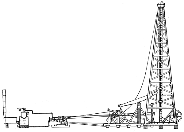
Off to one side of the derrick, at a distance of sixty to seventy-five feet, is placed an engine, usually of the traction-engine type. From this engine a belt passes to a power- or drive-wheel, supported by a framework which also supports a reel employed in driving the sand-pump.
To the derrick base on a suitable support is hung the walking-beam, one end of which is connected by a pitman to the drive-wheel, while the other end is fastened to the rope, when drilling, by means of the temper-screw. On the opposite side of the derrick from the walking-beam is placed the bull-wheel, which is employed in raising and lowering the drill in the hole, When not in use, the sand-pump stands to one side within the derrick; when used, it is employed alternately with the drill--that is, after drilling for a certain length of time the drill is removed and the sand-pump lowered to remove the water and cuttings from the hole, and thus facilitate the drilling operations. It is operated by a friction-wheel working on the rim of the power-wheel, which can be thrown on or off at will.
The temper-screw consists of a split-nut fastened to the lower end of a steel frame, four feet six inches long, which is fastened to the walking-beam. In the split-nut a long steel screw operates. At the lower end of the frame is a clamp enclosing the split-nut, which, when tightened, forces the two parts of the nut together, making it in reality solid or like one piece. Screwing into the nut is a long, steel feed-screw, to the lower end of which is a ball-bearing swivel, linked to which is a clamp for holding the rope, A cross-brace is set-screwed to the feed-screw just above the swivel, by means of which the screw is fed through the nut, thereby lowering the drill in the hole, thus constituting the action of feeding. The object of the split-nut is to facilitate the setting back of the frame at the end of the feed; that is, by unclasping the split-nut the frame can be slipped down upon the feed-screw; otherwise it would have to be screwed back, which would necessitate considerable time and consequent delay.
The drill part proper consists of several separate parts, and goes by the name of the string, or line of tools, and is about sixty-five feet in length. Beginning with the bit end, the parts are as follows: Bit, auger-stem, jars, sinker-bar, and rope-socket. A rope extends from the rope-socket to the bull-wheel, by way of the top or head sheave. The bit has several forms, which differ in shape with the purpose for which they are intended and the formation to be worked. There are two general forms, known as the cutter-bit, and the reamer. The cutter-bit is chisel-shaped, while the reamer is H-shaped, and is used to straighten up the hole from time to time. The auger-stem is a section of rod screwed to the bit to give sufficient weight for cutting. The jars are made up of two links, which slide one upon the other, and are fastened to the sinker-bar and auger-stem above and below. The object of the jars is to loosen the bit if it gets caught in the hole. The links slide one upon the other for a certain distance, thus allowing the upper part of the line of tools to acquire sufficient momentum to pick up the bit. Their action is especially useful in fissured ground, where the bit is liable to be caught by jamming in a fissure. The sinker-bar is also a section of rod, like the auger-stem, the purpose of which is to keep the rope taut. To the top of the sinker-bar is screwed the rope-socket, in which is inserted the rope.
Method of Operation of Churn Drill
When drilling begins the drill is lowered until the two parts of the jars meet; it is then raised until only four inches of clearance is left between links. The power-wheel is then turned until the pitman is at the top of the stroke; the walking-beam is then at the lowest part of its stroke, In this position the temper-screw is attached to the rope. From twenty to thirty feet of rope are then unwound by turning the bull-wheel, which loose rope is wound up in a large coil on the platform about the driller.
Starting up the engine causes the walking-beam to move up and down, thus transmitting to the drill through the rope a chopping or reciprocating motion, As the hole is deepened the bit must be lowered, which is accomplished by unscrewing the temper-screw. The action of feeding also tends to turn the line of tools, through friction in the swivel, which is of positive advantage, as it keeps the hole round, but if it is continued in one direction to the end of the feed the rope will have become very much tangled. This is obviated by allowing the drill to turn while feeding for several revolutions, then reversing the direction of the turning of the swivel, at the same time feeding as before, By making the same number of turns first in one direction and then in the other, the rope is kept free of twist and tangle. The strokes of the walking-beam range from thirty to forty-five per minute. Shifts change at noon and midnight. The sand-pump is geared up so that it can be raised at a high speed, with a minimum loss of time, It is lowered by gravity.
It is customary, at the beginning of operations, to sink the first 50 or 100 feet of the hole by driving the casing as a drive-pipe and sand-pumping the material from the inside. In connection with the driving of the casing, the line of tools, without the jars, may be employed. It is raised and dropped, thus loosening up the material at the bottom of the hole and facilitating the driving of the casing. The walking-beam is not brought into use in this preliminary work, movement being given to the drill by a loop of rope passing over the crank upon the power-wheel and inclosing the drill rope, as it descends from the sheave above, at some distance above the bull-wheel. The bull-wheel, being held fast, causes the line of tools to rise as the rope is pulled from a straight line by the rotation of the power-wheel. The amount that the drill is raised will depend on the position of the crank upon the power-wheel; i, e , whether the radius is long or short. The operation of sinking the hole, until the full length of the line of tools can be employed, is known as spudding, A record is obtained by preserving the cuttings raised by the sand-pump, and when care is taken a very complete log is possible.
Description of the Diamond Drill
The diamond drill employed in deep-well boring is provided with a hydraulic feed, which consists of a cylinder through which passes the hollow drill-rod. Enclosing the drill-rod is the so-called drive-rod, which in turn is enclosed by the piston-rod. To one end of the piston. rod is attached the piston. The other end of the rod is fastened to the drive-head. The drive-head is provided with two sets of ball bearings, between which is a flanged collar securely fastened to the drive-rod. Any movement of the piston, caused by forcing water into one end of the cylinder and allowing it to escape from the other, will produce a similar movement in the drive-rod. Below the cylinder the drive-rod is provided with a clamp-head or chuck, by means of which it can be securely fastened to the drill-rod proper. Any movement of the piston will then be transmitted at once to the drill-rod.
Plate VIII--Diamond Drill, Hydraulic Feed
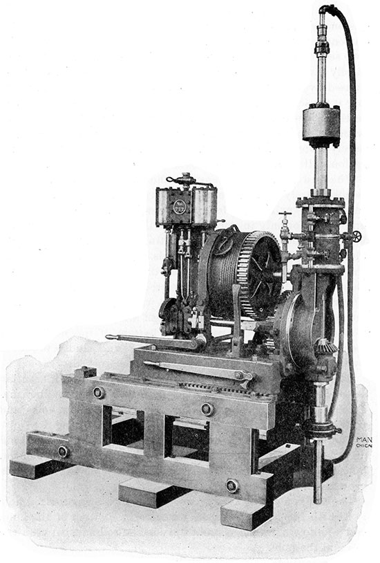
The feed is extremely sensitive and easily regulated, as it depends entirely upon the amount of water that is fed to the cylinder. The cylinder is fed by a force-pump. The feed may be employed not only in forcing the drill downwards against the bottom of the hole but also in lifting the rod. The rod may also be lifted by cable, which winds upon the drum driven by the actuating mechanism of the drill, and passes over the sheave placed on the derrick top erected above the drill. The upper section of the rod is provided with a flexible ball-bearing jetting connection, by which, through a hose, water is brought to and forced down the rod to the bottom of the hole, thence rising upwards bears with it the cuttings and sludge produced by the action of the drill on the formation worked.
There is another method of feeding, namely, the "differential-screw feed," which is employed mainly on the smaller machines, such as are used for comparatively shallow holes and underground work.
The hydraulic feed is especially adapted to large-sized and deep wells. It is heavy and, therefore, less convenient to move, but, due to the ease and rapidity of change of the feed, it is growing in favor.
The rod is a strong iron or steel tube, with a small-sized hole to furnish free passage for the water to the bottom of the hole, and to allow a return current outside the rod and between the rod and the hole.
The essential parts of the drill proper are at the bottom or lower end of the rod, and are, in the order in which they occur, from the bit up, as follows: The bit, the core-lifter, the core-barrel.
The bit is the part which contains the diamonds. The arrangement of the diamonds on the bit is quite varied, the main idea being to so place them as to cause their respective tracks or courses to lap, thus evenly and uniformly wearing away the rock. It is common practice to provide grooves in the sides and edge of the bit to insure a more even flow of water for removing the cuttings from the bottom of the hole. The action of the diamond drill upon the rock is not cutting, but grinding-the diamonds being set so as to slide, and when forced down will drag out or grind a groove. The diamonds or stones used for drilling are borts (defective brilliants) and carbons (colored diamonds), and are obtained largely from South America.
Above the bit is the core-lifter, of which there are two general forms, namely: The cossette and the split-ring. The cossette form consists of a series of spines, which are attached at the lower end around the inside of the body of the lifter. The core in rising, or the drill in passing downward, raises them in a vertical position, but when the operation is reversed, the drill-rod and lifter being raised, they catch in the sides of the core and prevent its withdrawal. The split-ring core-lifter is, as the name indicates, a split-ring which encloses the core. The ring is tapering and rests in a tapering recess, which is an enlargement of the hole through the section of the rod which constitutes the body of the lifter. As the drill works its way downward the core rises through the core-lifter, pushing the split-ring in the upper and larger part of the tapering recess, thus allowing it to expand to its normal shape, and presenting practically no resistance to the passage of the core through it. When, however, the full length of the feed is reached, and it is desired to raise the core, the split-ring attached to the core is drawn downward into the narrowing recess by the raising of the drill-rod, and is consequently caused to tighten its grip on the core. To prevent slipping, the inner surface of the split-ring is provided with teeth, which point upward and inward. These teeth will then set upon the core and hold it rigidly, allowing it to be broken off and raised to the surface.
Next in order above the core-lifter is the core-barrel, which consists of a hollow rod, with the opening sufficiently large to allow the entrance of the core, and is as long as it is desirable to have the feed, which may range from two to ten feet. Occasionally, when especially friable and soft strata are worked, to prevent the breaking off and consequent wearing away of the core, an inner core-barrel is inserted, which is provided with ball bearings at the top and bottom ends. Into this inner casing the core is pushed, and by means of light springs it is supported and partially protected from the wash-water, the greater part of which passes on the outside of the inner casing. By this means complete records are often obtainable, which would otherwise be partially destroyed, the exact amount worn away not being known.
Method of Operation of Diamond Drill
The drill having been set up in the position desired, and a shallow opening or hole made, the proper length of the rod is added and lowered into the hole. Power is then turned on and the feeding begun; the full advance being made, the rod is raised and the core removed. This operation is repeated until the required depth is reached or reaming is necessary. After a certain advance has been made, another section of rod must be added. The character of the cuttings is noted and the cores are preserved, which will constitute the log of the well.
An increase or decrease of the water escaping from the hole furnishes important information as to the character of the water met. When hydraulic waters are met, it is quite often the case that no water need be fed to the rod, the hole being kept clean by the rising of such waters. In such instances the quality of the water is, of course, readily determinable.
Description of the Calyx Drill
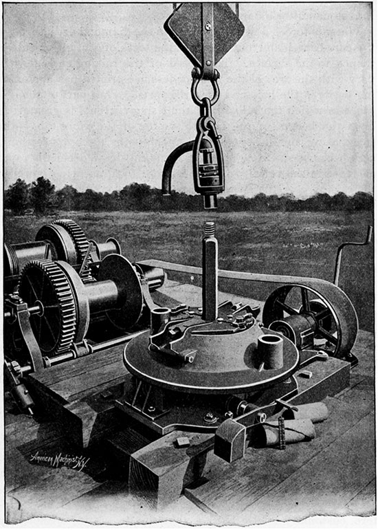
The large calyx drills are driven by horse or steam power. A light yet strong derrick is erected above the well, at the top of which a sheave is placed. From this sheave the drill-rod is suspended by block and tackle, which is operated by a drum driven by the power turning the drill. (Plate IX.) The feed is thus regulated by the drum, while the turning of the rod is accomplished by a simple arrangement of belting and gears. (Plate X.) The jetting-head is provided with a ball-bearing swivel, thus allowing the rod to turn independent of the water connection and supporting attachment. The surface plant is thus markedly different from that of a diamond drill, which is largely necessitated by the size and weight of the rod. The size of the bore for deep holes ranges from 2 1/8 to 10 inches in diameter, As no diamonds are required, there is no reason for taking out small cores.
Plate IX--Davis-Calyx Drill, Surface Plant
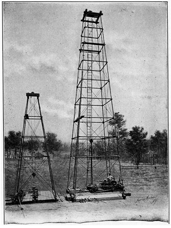
Plate X--Davis-Calyx Drill, Driving Mechanism
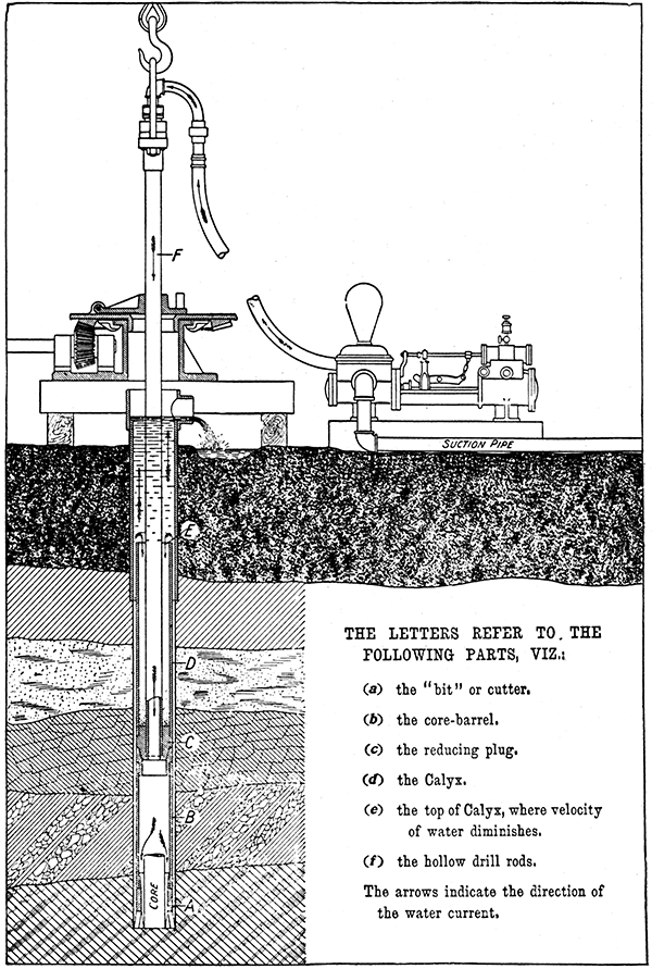
The bit or cutter is a metallic shell, with peculiar teeth in one end, and a thread cut in the other for screwing into the core-barrel.
The core-barrel is a tube, which is always larger in diameter than the drill-rods, but of the same outside diameter as the main body of the cutter.
The drill-rods are tubes which screw into the upper end of the core-barrel by means of a reducing plug, and extend downward from the surface.
The calyx is also a tube or series of tubes equal in diameter to the core-barrel. It surrounds the lower drill-rod, rests on the reducing plug, and is open at the upper end, thus leaving a space between the drill-rod and the inside of the calyx. The purpose of this space is explained further on.
Method of Operation of Calyx Drill
The principle involved in the calyx drill is to, all intents and purposes the same as in the diamond drill. In the case of the former, however, drilling is accomplished by means of steel teeth, instead of with diamonds. Here, too, the torsion of the drill-rod is brought into play, the teeth catching on the bottom of the hole, holding until by the torsion or twist of the rod sufficient energy is accumulated to overcome the bite. The instant that the surface strain exceeds the resistance of the turning below, the cutter tears loose, cutting fragments from the groove in which it rests. The strain being relieved, the cutter again comes to rest and is again torn from its bite. The repetition of these movements produces an action which has been likened to that of a mallet and chisel in a stone-cutter's hands,
Water is forced down the rod, as in the diamond drill, through the core-barrel and out between the teeth of the bit or cutter, thence to the surface. The speed of the raising currents will vary with the area of the more or less constricted passage existing between the hole and the drill parts. That part of the distance in which the velocity of the rising currents is greatest is from the bottom of the hole to the top of the calyx tube--the space being small, beyond this upper point the cross-sectional area becomes suddenly enlarged, thus causing a decidedly rapid decrease in the velocity of the currents. The carrying power of the raising currents decreasing with the velocity causes a backward movement or settlement of the materials in suspension, which, being unable to settle against the strong raising currents, are caught in the calyx tube, and that, too, in the order that they occupied in their original position in the strata. Two records are thus obtained--the core and the cuttings or "chip record."
By means of the calyx the hole is kept clear of sludge, the importance of which cannot be too strongly emphasized, not only from the standpoint of free and easy drilling, but also to prevent the "jamming in" of the drill by sludge. The core is removed, sections of rod added and water fed to the rod in a similar manner as is employed in the diamond drill. (Plate XI.)
Plate XI--Sectional view of Davis Calyx drill as it would appear could it be seen at work underground.
The speed of the tooth cutter is remarkable in the majority of rocks--many shales and sandstones being cut at the rate of three-fourths inch per revolution. With very hard rock, however, it may be more economical to employ a diamond bit, and, when it is possible, that is, when the size of the hole will allow, such a bit may take the place of the cutter. With the larger sizes this interchange of bits is impossible, or rather impracticable, due to the excessive cost of the diamond bit. It is, therefore, customary to use chilled shot, by the use of which very hard rock can be cut with comparative ease, and that, too, at a low cost. There are, however, some limitations to the chilled-shot process; first, it will not work well in soft, pasty rock and, second, it will not drill past crevices unless the crevice can be cemented, which in itself is expensive and delays the work, Again, some crevices are too large to cement, while others have streams running through them, thus precluding the idea of cementing.
It is then evident that both the cutter and chilled-shot methods are limited, but one will usually work where the other will not as a rule. To illustrate, say that a very hard stratum of rock is struck while drilling with the cutter, the chilled-shot process can be substituted; again, if a crevice is met, change back to the cutter, which, although it may work slower, may be employed to cut past the objectionable point, cutting a new groove for the shot process again, or cementing may be resorted to.
The chilled-shot process consists in using a blank bit; that is, one without teeth, but having a smooth or annular edge. This blank bit fits into the groove formed by the toothed bit or cutter, On the sides of the bit are grooves reaching to the lower edge. Through these grooves the chilled shot is fed to the bottom of the hole, and as it wears out and is lost, the supply can be maintained, Pressure is given by the weight of the drill-rod above, which, combined with turning, rubs the shot into the rock and thus cut and scour it out, the wash water bearing away the loosened material.
Casing Drill-holes
Casing consists of placing a wooden or iron lining in the hole in order to maintain its sides. Wood is not used for lining deep-bore holes, Iron or steel are the only suitable materials, and at the same time are fairly inexpensive, Casing is, as a rule, necessary as drilling proceeds, unless the hole is of moderate depth and the formations pierced are solid and will maintain their position until the hole is completed,
In the churn-drill process, there is, in some respects, greater necessity of casing the hole as soon as drilled; that is, keeping the casing a short distance above the bottom, because of the lashing and rubbing of the rope and line of tools against the sides, which causes them to crumble and cave in. The wash water in the case of the diamond and calyx drills also tends to loosen the soft formation of the walls of the hole, but not to such an extent as does the rubbing of the rope in the churn-drill method.
With the churn drill the hole is made sufficiently large to allow the placing of the casing without extra enlargement. The operation of casing is, in this case, then, quite simple--the casing can be driven from time to time without removing the line of tools. This is accomplished by raising the tools until the middle of the sinker-bar comes to the top of the casing; a driving block is then clamped to the bar, which, being raised and dropped will drive the casing down. Sections are added as needed until the full depth has been lined. When drilling is done by diamond or calyx drills, the hole must be reamed out to make room for the casing, provided casing is necessary during drilling operations, Reaming will then alternate with drilling.
It is often necessary to shut off certain strata to prevent the contamination of the desired product, as when oil, gas and briny-water strata overlie the sheet of water which it is desired to open up. Such strata may be closed after the hole is completed, but it is usually preferable to close the same as soon as possible after penetration. Quicksand strata must be closed at once, or further work of drilling will be interfered with, and there will also be the risk of a cave-in.
It was formerly necessary to remove the bit and core-barrel and substitute for them a reamer, but within the last few years a reamer has been devised by means of which drilling and reaming may be carried on simultaneously, thus allowing the casing to be placed and driven from time to time independent of drilling operations. The driving of the casing is accomplished in this case by an improvised pile driver, the rod being removed during the operation.
When it is especially desirable to close the strata as soon as passed through it may be done by a new device lately brought into practical use, which is intended, however, for shallow work only, as working gravel beds and superficial coverings. The casing is driven continuously and at the same rate that drilling is carried on, thus maintaining the same distance between the bit and the bottom of the casing. This is accomplished by a driving block, which is attached to the cable or a rod connecting with the line of tools. The weight of the tools drives the casing.
As the wells discussed in this report are under 1500 feet in depth many of the difficulties encountered in drilling holes up into the thousands of feet are not experienced; then, too, the formations met with are with a few possible exceptions easily worked with all forms of drilling devices.
In several localities, especially in the southeastern portion of the state, a very hard limestone, commonly called "bastard rock," is found, but by far the most difficult formation to drill is the cherty formation of Galena, which is not only very hard but is in most parts fissured. Diamond drills cannot conveniently be employed in such rock, and churn drills are frequently troubled by the catching of the tools. The calyx drill, using both the cutter and chilled shot, together with cementing, can readily cope with such conditions.
The self-contained forms of churn drills are largely used for the drilling of wells and for prospecting purposes, especially in prospecting for oil, gas, and coal.
Opening Up and Clearing Out Wells
When a well has been sunk to the stratum in which water is known or believed to occur and nothing is found, or it is obtained in such small quantities as to be of no special value, it is usual to try opening up the bottom of the hole. This is accomplished by firing off a charge of explosive, usually nitroglycerin, which has been lowered to the desired point. A cavity is then formed or the formation is greatly disturbed and fissured, thus producing a large area of fissured and broken rock through which the water can readily pass to the hole. The same method of procedure is often followed with a well which has been yielding a sufficient supply but begins to fall off or ceases altogether.
It is not uncommon, however, to bring about results exactly the reverse of what is expected, namely, the entire cutting off of the supply, Several cases are on record where very good wells have been rendered worthless by such a process of opening up or clearing out.
Prev Page--General Discussion--Classification || Next Page--General Discussion--Beverages
Kansas Geological Survey, Geology
Placed on web April 7, 2017; originally published 1902.
Comments to webadmin@kgs.ku.edu
The URL for this page is http://www.kgs.ku.edu/Publications/Bulletins/Vol7/10_prosp.html