![]()
Prev Page--Geologic History || Next Page--Fluctuations of Water Table
Ground Water
Principles of Occurrence
The fundamental principles governing the occurrence and movement of ground water have been set forth in detail by Meinzer (1923), and have been summarized by Moore (1940) as they apply to Kansas. Only essential statements will be made here, and the reader is referred to the reports of Meinzer and Moore for a more detailed discussion.
Ground water is derived chiefly from water that falls as rain or snow. A part of this water runs off directly in streams to the sea, a part evaporates, a part is consumed by the plants, and a part sinks through pore spaces in the soil and underlying rocks to the water table where it enters the zone of saturation. Much of the water in the zone of saturation eventually returns to the surface through seeps, springs, or wells, or is discharged by plants or when it is near the surface through evaporation from the soil. Some ground water, however, percolates directly into surface streams. The porous rocks below the water table as a rule are saturated. Those that are sufficiently permeable yield water to wells sunk into them. In the more permeable rocks, such as beds of sand and gravel and some of the sandstones, the individual pores are interconnected and are large enough so that the water moves freely under the influence of gravity, but in less permeable rocks, such as shale and fine-grained sandstone, the pores are so small that water moves through them with difficulty.
In this area the wells that yield the greatest quantities of water penetrate beds of unconsolidated sand and gravel. Wells that penetrate shale yield proportionately very small quantities of water.
Physical and Hydrologic Properties of Water-bearing Materials
The quantity of water that an aquifer will yield to wells depends upon the physical and hydrologic properties of the material composing it. Detailed geologic descriptions of materials encountered in drilling, such as those included in the logs at the end of this report, are useful in estimating the quantity of water available in a given area, but more exact quantitative estimates of water supplies necessarily are based on more precise analyses of these earth materials in the laboratory or by field tests.
An intensive test-drilling program was conducted during the early part of this investigation in the area in which the present Wichita well field was later located, and many samples of the water-bearing materials were carefully collected. Quantitative analyses of them were made, in part by V. C. Fishel in the hydrologic laboratory of the U.S. Geological Survey in Washington, and in part in field laboratories by G. H. Von Hein and Charles C. Williams. These studies included mechanical analyses, determinations of apparent specific gravity, porosity, moisture equivalent, specific yield, and coefficient of permeability. Mechanical analyses and determinations of permeability were made for most of the samples collected, but other physical values were determined only for a part of them. The physical properties of a few samples of silt and dune sand collected from outcrops also were studied. The results of laboratory studies are summarized in Table 7.
Pumping tests were made at all of the 25 new Wichita municipal wells, at well 608 near Wichita, owned by the Kansas Gas and Electric Company, and at a few other wells in the area. The data obtained from these tests have been studied and determinations of permeability and transmissibility have been made.
Mechanical Analyses
Definition
A mechanical analysis of granular material consists of separating into groups the grains of different sizes and determining what percentage of the total sample, by weight, each size group constitutes.
Laboratory Methods and Determinations
In preparation for making the laboratory analyses, samples collected from the cable-tool test holes or from outcrops were dried, placed in a large mortar, and adhering lumps of material were gently separated. Representative samples of the desired volume were obtained by repeated quartering through a sample splitter. Mechanical analyses of carefully weighed samples that averaged about 50 grams each were made. The samples were placed in a set of standard 3-inch screens and were shaken vigorously for 30 minutes in a rotary shaker. The fractions of the sample remaining on each screen were weighed on a precision balance.
The mechanical analyses were made in order to determine the percentage of each grade of material present in the sample so that comparison with other materials could be made. Methods have been devised for making indirect determinations of physical properties from mechanical analyses, but only direct methods were employed in this study. The results of the mechanical analyses given in Table 7 illustrate the differences in the grain size of the constituent rock particles and the degree of homogeneity in the water-bearing materials in the Wichita well-field area.
Porosity
Definition
The porosity of a rock or rock aggregate is its property of containing interstices without regard to size, shape, or arrangement of openings. Porosity is expressed as the percentage of the total volume occupied by interstices.
Laboratory Determinations
The porosity of some of the samples studied was determined as a step in the calculation of specific yield. The porosity of the samples given in Table 7 ranged from 24.1 to 60.2 percent by volume. In general, the larger porosities occur in the finer-grained sediments and vice versa.
Table 7.--Physical properties of water-bearing materials.
| Well number or location | USGS laboratory number (a) | Depth of sample (feet) | Method of sampling (b) | Mechanical analyses (percent by weight) | Apparent specific gravity | Porosity (percent by volume) | Moisture equivalent (percent by volume) | Specified yield (percent by volume) | Coefficient of permeability | Weighted average coefficient of permeability | ||||||||||
|---|---|---|---|---|---|---|---|---|---|---|---|---|---|---|---|---|---|---|---|---|
| From | To | Medium and coarse gravel (larger than 2.0 mm) | Fine gravel (2.0-1.0 mm) | Coarse sand (1.0-0.50 mm) | Medium sand (0.50-0.25 mm) | Fine sand (0.25-0.125 mm) | Very fine sand (0.125-0.062 mm) | Silt and clay (less than 0.062 mm) | Silt (0.062-0.005 mm) | Clay (less than 0.005 mm) | Loss in acid | |||||||||
| SW sec. 27, T. 18 S., R. 4 W. | 2397 | outcrop | H | 0.7 | 1.0 | 2.7 | 55.1 | 28.5 | 12.0 | 1.56 | 40.7 | 40.2 | 1.0 | |||||||
| SW sec. 27, T. 18 S., R. 4 W. | 2398 | outcrop | H | 0.9 | 1.2 | 2.3 | 53.1 | 28.4 | 14.1 | 1.58 | 39.2 | 38.9 | 1 | |||||||
| 167 | 2390 | 67.5 | 71.0 | O | 1.7 | 40.5 | 20.8 | 7.0 | 1.4 | 28.6 | 2.25 | 27.4 | (c)2.0 | 25 | 1 | |||||
| 167 | 2395 | 85.0 | 110.0 | O | 2.1 | 5.1 | 26.7 | 47.5 | 14.6 | 1.7 | 0.7 | 1.58 | 40.8 | 3.3 | 36 | 250 | ||||
| NE sec. 33, T. 22 S., R. 3 W. | (d) outcrop | H | 0.1 | 3.5 | 46.6 | 38.6 | 6.2 | 5.0 | ||||||||||||
| NE sec. 33, T. 22 S., R. 3 W. | (d) outcrop | H | 0.6 | 36.7 | 44.1 | 8.3 | 10.3 | |||||||||||||
| NE sec. 33, T. 22 S., R. 3 W. | (e) outcrop | H | 1.4 | 53.2 | 35.6 | 8.0 | 1.8 | |||||||||||||
| NE sec. 33, T. 22 S., R. 3 W. | (e) outcrop | H | 0.2 | 4.6 | 60.7 | 29.0 | 4.5 | 1.0 | ||||||||||||
| NE sec. 33, T. 22 S., R. 3 W. | (f) outcrop | H | 1.7 | 56.2 | 36.4 | 5.1 | 0.6 | |||||||||||||
| NE sec. 33, T. 22 S., R. 3 W. | (f) outcrop | H | 0.7 | 42.4 | 49.4 | 6.7 | 0.8 | |||||||||||||
| 310 | 2408 | 31.0 | 32.5 | C | 3.3 | 6.8 | 36.5 | 45.9 | 6.5 | 0.6 | 0.9 | 1.61 | 38.8 | 3.0 | 34 | 500 | ||||
| 310 | 2409 | 100.2 | 103.0 | C | 6.4 | 12.0 | 35.6 | 30.1 | 12.9 | 2.1 | 1.1 | 1.71 | 36.0 | 1.9 | 33 | 360 | ||||
| 310 | 2410 | 125.0 | 129.0 | C | 8.7 | 26.0 | 43.4 | 18.8 | 1.7 | 0.5 | 0.9 | 1.69 | 35.8 | 2.3 | 31 | 2100 | ||||
| 310 | 2411 | 149.0 | 154.5 | C | 8.3 | 24.1 | 30.1 | 26.0 | 5.9 | 2.4 | 3.1 | 1.69 | 35.0 | 5.0 | 29 | 110 | 357 | |||
| 329 | 25.0 | 27.0 | C | 29.1 | 19.3 | 20.7 | 20.4 | 8.8 | 1.1 | 0.6 | 570 | |||||||||
| 329 | 27.0 | 29.0 | C | 30.5 | 24.5 | 29.2 | 15.0 | 0.6 | 0.1 | 0.2 | 2240 | |||||||||
| 329 | 43.6 | 45.3 | C | 12.5 | 10.7 | 26.6 | 41.8 | 7.7 | 0.5 | 0.2 | 970 | |||||||||
| 329 | 53.4 | 55.0 | C | 45.7 | 39.2 | 12.9 | 1.9 | 0.3 | 0.1 | 5290 | ||||||||||
| 329 | 56.5 | 61.0 | C | 43.6 | 31.1 | 15.4 | 9.1 | 0.6 | 0.1 | 3570 | ||||||||||
| 329 | 62.0 | 64.0 | C | 48.1 | 39.1 | 10.3 | 2.1 | 0.3 | 0.1 | 10920 | ||||||||||
| 329 | 2412 | 64.0 | C | 55.0 | 24.3 | 15.0 | 4.3 | 1.1 | 0.2 | 0.5 | 1.78 | 32.0 | 2.0 | 28 | 4600 | |||||
| 329 | 69.0 | 70.0 | C | 18.8 | 25.4 | 37.7 | 15.5 | 2.4 | 0.2 | 0.2 | 2140 | |||||||||
| 329 | 72.5 | 74.0 | C | 29.9 | 28.4 | 18.5 | 17.6 | 4.4 | 0.6 | 0.7 | 1770 | |||||||||
| 329 | 95.0 | 100.0 | C | 3.5 | 16.0 | 44.8 | 27.5 | 5.6 | 1.2 | 1.3 | 140 | |||||||||
| 329 | 100.0 | 104.0 | C | 6.3 | 17.6 | 39.0 | 26.6 | 6.9 | 1.6 | 2.0 | 570 | |||||||||
| 329 | 2413 | 120.0 | C | 1.8 | 14.0 | 37.5 | 19.2 | 4.4 | 23.6 | 1.78 | 32.0 | 3.8 | 27 | 17 | ||||||
| 329 | 121.2 | 124.0 | C | 2.8 | 28.3 | 51.6 | 14.7 | 2.0 | 0.2 | 0.4 | 2240 | |||||||||
| 329 | 186.0 | 188.0 | C | 16.3 | 18.4 | 45.7 | 18.5 | 1.0 | 0.1 | 0.1 | 2790 | |||||||||
| 329 | 192.0 | 203.5 | C | 4.8 | 18.3 | 57.6 | 15.0 | 1.7 | 0.7 | 2.0 | 1230 | |||||||||
| 329 | 2414 | 207.0 | C | 5.2 | 15.5 | 45.9 | 20.0 | 2.5 | 1.8 | 9.5 | 1.80 | 30.0 | 5.0 | 24 | 255 | |||||
| 329 | 215.0 | 217.0 | C | 4.4 | 20.3 | 47.8 | 26.4 | 0.8 | 0.1 | 0.1 | 2240 | |||||||||
| 329 | 219.0 | 225.2 | C | 17.8 | 34.3 | 34.0 | 12.8 | 1.0 | 0.1 | 3740 | ||||||||||
| 329 | 249.0 | 252.0 | C | 6.7 | 17.4 | 43.8 | 18.8 | 4.0 | 2.1 | 5.9 | 115 | 830 | ||||||||
| 358 | 5.8 | A | 1.41 | 42.5 | 30 | |||||||||||||||
| 400 | 2375 | 7.5 | C | 0.2 | 0.6 | 4.1 | 9.3 | 12.5 | 46.0 | 27.9 | 1.29 | 53.0 | 36.1 | 17 | 0.1 | |||||
| 401 | 26.5 | 29.2 | C | 6.8 | 0.6 | 1.9 | 7.9 | 68.4 | 7.3 | 7.1 | 60 | |||||||||
| 401 | 29.2 | 34.0 | C | 15.0 | 20.1 | 20.4 | 30.5 | 11.4 | 0.8 | 1.7 | 520 | |||||||||
| 401 | 2376 | 34.0 | C | 16.0 | 11.7 | 17.7 | 36.8 | 14.7 | 1.2 | 1.8 | 250 | |||||||||
| 401 | 38.0 | 40.0 | C | 28.4 | 21.3 | 29.0 | 15.8 | 2.6 | 1.2 | 1.7 | 530 | |||||||||
| 401 | 40.0 | 41.6 | C | 7.2 | 39.2 | 39.2 | 10.8 | 1.4 | 0.4 | 1.7 | 2140 | |||||||||
| 401 | 42.9 | 51.6 | C | 0.1 | 1.0 | 6.0 | 34.7 | 32.9 | 11.6 | 13.6 | 10 | |||||||||
| 401 | 78.5 | 80.0 | C | 16.1 | 13.2 | 11.1 | 9.4 | 10.8 | 12.0 | 27.4 | ||||||||||
| 401 | 75.5 | 78.5 | C | 22.3 | 6.2 | 11.1 | 14.5 | 14.0 | 9.9 | 22.0 | 1 | |||||||||
| 401 | 97.0 | 100.2 | C | 24.6 | 11.1 | 11.1 | 14.2 | 11.6 | 10.8 | 16.6 | 3 | |||||||||
| 401 | 107.5 | 110.0 | C | 4.6 | 13.6 | 33.5 | 42.0 | 4.8 | 0.6 | 0.9 | 540 | |||||||||
| 401 | 111.0 | 112.0 | C | 10.4 | 11.1 | 35.1 | 39.4 | 3.0 | 0.4 | 0.6 | 300 | |||||||||
| 401 | 112.0 | 113.0 | C | 3.2 | 13.1 | 39.2 | 39.2 | 3.5 | 0.7 | 1.1 | 690 | |||||||||
| 401 | 2377 | 114.0 | C | 1.3 | 6.0 | 36.0 | 52.4 | 3.3 | 0.2 | 0.5 | 930 | |||||||||
| 401 | 119.4 | 124.5 | C | 2.9 | 24.4 | 42.2 | 24.3 | 4.6 | 0.7 | 0.8 | 260 | |||||||||
| 401 | 127.2 | 128.0 | C | 0.4 | 3.2 | 32.8 | 56.0 | 4.7 | 1.8 | 1.1 | 1050 | |||||||||
| 401 | 130.0 | 136.0 | C | 1.8 | 10.8 | 30.6 | 45.9 | 8.7 | 0.9 | 1.3 | 100 | |||||||||
| 401 | 145.0 | 147.0 | C | 9.6 | 22.6 | 25.1 | 12.7 | 15.0 | 7.8 | 7.1 | 25 | 257 | ||||||||
| 403 | 2382 | 5.3 | A | 2.1 | 1.2 | 1.9 | 2.0 | 2.9 | 52.8 | 37.0 | 1.11 | 60.2 | 65.0 | 0.1 | ||||||
| 403 | 25.0 | 28.0 | C | 1.2 | 6.5 | 20.9 | 60.7 | 9.9 | 0.5 | 0.3 | 920 | |||||||||
| 403 | 2383 | 29.7 | C | 17.8 | 12.4 | 21.7 | 36.4 | 9.7 | 0.5 | 0.2 | 560 | |||||||||
| 403 | 29.7 | 31.8 | C | 15.7 | 21.5 | 32.9 | 25.6 | 3.5 | 0.3 | 0.4 | 1300 | |||||||||
| 403 | 31.8 | 34.6 | C | 6.6 | 9.0 | 20.5 | 51.5 | 11.7 | 0.4 | 0.3 | 832 | |||||||||
| 403 | 34.6 | 39.6 | C | 4.2 | 7.3 | 26.9 | 40.3 | 14.8 | 3.2 | 3.2 | 164 | |||||||||
| 403 | 40.9 | 43.1 | C | 7.3 | 9.9 | 31.3 | 29.2 | 11.2 | 4.2 | 6.7 | 30 | |||||||||
| 403 | 48.2 | 48.5 | C | 29.6 | 25.8 | 25.1 | 8.4 | 4.0 | 4.3 | 6.8 | 2140 | |||||||||
| 403 | 48.5 | 49.0 | C | 28.5 | 30.0 | 26.8 | 11.0 | 3.4 | 0.2 | 10900 | ||||||||||
| 403 | 49.0 | 50.1 | C | 20.8 | 23.1 | 30.1 | 18.7 | 5.7 | 0.6 | 1.0 | 690 | |||||||||
| 403 | 50.1 | 51.0 | C | 18.4 | 33.6 | 36.8 | 9.4 | 1.8 | 5290 | |||||||||||
| 403 | 51.0 | 53.1 | C | 19.4 | 29.9 | 28.5 | 7.6 | 2.0 | 1.8 | 10.8 | 50 | |||||||||
| 403 | 54.1 | 57.9 | C | 0.6 | 8.4 | 23.5 | 41.3 | 23.0 | 1.8 | 1.4 | 320 | |||||||||
| 403 | 87.3 | 93.0 | C | 8.2 | 19.6 | 8.1 | 5.1 | 25.0 | 14.5 | 19.5 | 4 | |||||||||
| 403 | 78.5 | 80.0 | C | 16.1 | 13.2 | 11.1 | 9.4 | 10.8 | 12.0 | 27.4 | ||||||||||
| 403 | 123.2 | 130.0 | C | 18.1 | 17.4 | 28.1 | 23.8 | 5.7 | 2.2 | 4.7 | 30 | |||||||||
| 403 | 130.0 | 133.0 | C | 12.7 | 26.6 | 37.7 | 17.1 | 3.0 | 1.0 | 1.9 | 140 | 316 | ||||||||
| 448 | 6.8 | A | 1.48 | 42.2 | 27 | |||||||||||||||
| 449 | 2419 | 13.0 | 16.0 | C | 23.0 | 9.4 | 16.2 | 33.6 | 14.3 | 2.1 | 1.2 | 1.74 | 33.4 | 3.5 | 28 | 30 | ||||
| 449 | 16.0 | 17.5 | C | 13.8 | 20.7 | 26.9 | 28.6 | 8.4 | 0.9 | 0.8 | 670 | |||||||||
| 449 | 46.0 | 48.0 | C | 6.4 | 6.8 | 20.2 | 48.6 | 15.8 | 1.4 | 0.9 | 510 | |||||||||
| 449 | 54.0 | 55.5 | C | 10.1 | 15.2 | 31.5 | 31.6 | 5.9 | 2.3 | 3.3 | 410 | |||||||||
| 449 | 58.5 | 62.0 | C | 6.4 | 13.6 | 40.6 | 32.7 | 5.4 | 0.4 | 0.9 | 920 | |||||||||
| 449 | 106.0 | 108.0 | C | 2.3 | 16.5 | 43.8 | 31.9 | 4.6 | 0.4 | 0.4 | 1500 | |||||||||
| 449 | 112.0 | 116.0 | C | 2.8 | 10.2 | 54.8 | 29.2 | 2.7 | 0.2 | 0.2 | 1760 | |||||||||
| 449 | 161.5 | 166.0 | C | 3.5 | 17.6 | 38.8 | 29.3 | 6.0 | 1.4 | 3.5 | 690 | |||||||||
| 449 | 2420 | 191.0 | 193.0 | C | 11.9 | 25.1 | 33.6 | 19.5 | 7.2 | 0.9 | 2.4 | 1.88 | 34.4 | 9.7 | 24 | 55 | ||||
| 449 | 193.0 | 196.0 | C | 6.4 | 21.7 | 33.2 | 24.5 | 10.8 | 1.5 | 1.9 | 336 | 308 | ||||||||
| 472 | 25.0 | 28.0 | C | 15.9 | 23.8 | 32.1 | 16.3 | 9.0 | 1.8 | 1.2 | 270 | |||||||||
| 472 | 30.0 | 34.0 | C | 17.7 | 25.1 | 27.3 | 20.4 | 7.4 | 1.5 | 0.6 | 1050 | |||||||||
| 472 | 36.0 | 40.0 | C | 10.2 | 23.2 | 32.7 | 24.1 | 8.2 | 0.8 | 0.8 | 1170 | |||||||||
| 472 | 54.0 | 56.0 | C | 18.6 | 16.1 | 16.6 | 25.7 | 5.9 | 1.9 | 12.2 | 50 | |||||||||
| 472 | 63.5 | 67.5 | C | 26.1 | 22.8 | 20.4 | 23.4 | 6.7 | 0.4 | 0.1 | 1050 | |||||||||
| 472 | 79.0 | 82.0 | C | 4.1 | 21.4 | 41.6 | 21.7 | 3.7 | 0.8 | 1.1 | 300 | |||||||||
| 472 | 100.5 | 103.0 | C | 7.9 | 14.4 | 31.0 | 34.8 | 7.8 | 2.2 | 2.0 | 360 | |||||||||
| 472 | 121.0 | 123.5 | C | 5.3 | 14.8 | 33.1 | 42.2 | 4.1 | 0.4 | 0.3 | 230 | |||||||||
| 472 | 132.0 | 136.0 | C | 6.0 | 25.7 | 43.5 | 19.2 | 4.3 | 0.6 | 0.6 | 920 | 330 | ||||||||
| 486 | 2378 | 4.8 | A | 2.2 | 21.8 | 45.7 | 20.5 | 9.8 | 45 | |||||||||||
| 486 | 8.0 | 11.4 | C | 1.1 | 12.9 | 41.3 | 23.4 | 21.3 | 15 | |||||||||||
| 486 | 11.5 | A | 1.53 | 39.5 | 30 | |||||||||||||||
| 486 | 11.4 | 13.6 | C | 1.7 | 6.0 | 34.2 | 41.5 | 12.2 | 4.4 | 40 | ||||||||||
| 486 | 18.2 | 19.4 | C | 3.0 | 3.3 | 12.4 | 47.5 | 29.1 | 4.0 | 0.8 | 400 | |||||||||
| 486 | 21.6 | 22.0 | C | 290 | ||||||||||||||||
| 486 | 2379 | 25.1 | C | 8.3 | 10.7 | 21.2 | 40.5 | 14.4 | 2.4 | 1.8 | 100 | |||||||||
| 486 | 25.1 | 26.9 | C | 6.4 | 12.9 | 20.9 | 41.5 | 17.1 | 1.0 | 0.2 | 540 | |||||||||
| 486 | 26.9 | 29.0 | C | 14.6 | 25.1 | 29.2 | 22.3 | 6.3 | 1.2 | 1.2 | 460 | |||||||||
| 486 | 29.7 | 32.4 | C | 9.0 | 12.6 | 22.8 | 48.6 | 4.7 | 1.3 | 1.0 | 1320 | |||||||||
| 486 | 41.5 | 45.0 | C | 28.4 | 22.9 | 19.8 | 25.6 | 3.1 | 0.1 | 270 | ||||||||||
| 486 | 45.0 | 45.3 | C | 6.8 | 10.2 | 16.6 | 44.0 | 13.9 | 3.5 | 4.8 | 190 | |||||||||
| 486 | 48.0 | 50.0 | C | 27.6 | 11.9 | 17.7 | 31.2 | 8.7 | 1.0 | 1.0 | 710 | |||||||||
| 486 | 2396 | 51.0 | C | 12.7 | 10.7 | 20.8 | 33.0 | 14.6 | 3.4 | 3.9 | 1.76 | 35.2 | 3.3 | 31 | 150 | |||||
| 486 | 51.5 | 55.0 | C | 24.4 | 20.7 | 27.8 | 20.1 | 3.8 | 1.0 | 2.1 | 710 | |||||||||
| 486 | 55.0 | 56.2 | C | 24.6 | 25.6 | 31.7 | 16.7 | 1.3 | 0.1 | 2140 | ||||||||||
| 486 | 2380 | 56.2 | C | 26.7 | 21.4 | 29.5 | 19.2 | 2.2 | 0.2 | 0.4 | 1400 | |||||||||
| 486 | 58.3 | 60.0 | C | 34.0 | 41.3 | 23.0 | 1.6 | 0.1 | 5300 | |||||||||||
| 486 | 75.9 | 76.2 | C | 3.8 | 14.0 | 28.0 | 36.4 | 16.2 | 1.0 | 0.6 | 540 | |||||||||
| 486 | 79.0 | 80.5 | C | 5.9 | 24.4 | 46.4 | 19.3 | 2.5 | 0.4 | 1.0 | 1170 | |||||||||
| 486 | 84.0 | 85.0 | C | 5.6 | 23.6 | 43.4 | 21.6 | 3.6 | 0.5 | 1.8 | 1170 | |||||||||
| 486 | 93.5 | 96.0 | C | 18.5 | 20.2 | 13.5 | 11.6 | 6.1 | 8.0 | 16.7 | ||||||||||
| 486 | 135.0 | 137.0 | C | 0.2 | 0.8 | 10.4 | 36.0 | 40.1 | 6.6 | 6.0 | 50 | |||||||||
| 486 | 142.0 | 146.0 | C | 3.6 | 21.5 | 55.8 | 17.9 | 0.9 | 0.1 | 0.2 | 830 | |||||||||
| 486 | 150.0 | 151.5 | C | 14.0 | 58.1 | 25.2 | 2.4 | 0.1 | 0.1 | 3570 | ||||||||||
| 486 | 155.2 | 155.5 | C | 2.3 | 37.1 | 55.0 | 3.6 | 1.2 | 0.2 | 0.5 | 220 | |||||||||
| 486 | 168.0 | 170.0 | C | 4.4 | 20.7 | 43.0 | 26.8 | 4.0 | 0.4 | 0.6 | 1050 | |||||||||
| 486 | 175.0 | 178.0 | C | 18.6 | 31.3 | 37.1 | 11.5 | 0.8 | 0.2 | 0.5 | 1500 | |||||||||
| 486 | 2381 | 179.0 | 180.0 | C | 6.5 | 24.5 | 43.9 | 8.6 | 8.8 | 2.4 | 3.9 | 20 | ||||||||
| 486 | 180.0 | 182.0 | C | 39.5 | 39.1 | 18.3 | 2.8 | 0.1 | 0.1 | 0.1 | 5292 | 572 | ||||||||
| 497 | 2418 | 52.0 | C | 54.9 | 21.6 | 13.1 | 8.9 | 1.2 | 0.4 | 0.5 | 700 | |||||||||
| 502 | 2.5 | A | 1.31 | 43.2 | 25 | |||||||||||||||
| 502 | 2415 | 4.5 | 5.5 | A | 0.7 | 1.6 | 4.2 | 31.7 | 47.9 | 8.1 | 6.4 | 1.37 | 42.6 | 33.9 | 8 | 0.4 | ||||
| 502 | 2416 | 6.5 | 7.0 | A | 21.6 | 9.4 | 14.8 | 32.3 | 17.4 | 3.3 | 1.6 | 1.84 | 31.0 | 3.9 | 26 | 200 | ||||
| 503 | 2417 | 231.8 | 232.8 | C | 4.3 | 13.4 | 52.2 | 27.2 | 2.6 | 0.7 | 0.3 | 1.69 | 36.6 | 1.3 | 34 | 1850 | ||||
| 511 | 2.9 | A | 1.30 | 50.0 | 19 | |||||||||||||||
| 549 | 8.6 | A | 1.66 | 36.7 | 33 | |||||||||||||||
| 557 | 10.8 | A | 1.52 | 40.0 | 33 | |||||||||||||||
| 560 | 6.0 | A | 1.62 | 34.5 | 14 | |||||||||||||||
| NW cor. sec. 2, T. 25 S., R. 2 W. | 10.7 | 14.7 | C | 0.1 | 0.4 | 1.6 | 19.0 | 41.9 | 12.6 | 21.1 | 3.4 | 20 | ||||||||
| NW cor. sec. 2, T. 25 S., R. 2 W. | 21.7 | 24.0 | C | 27.3 | 24.6 | 21.7 | 20.6 | 5.2 | 0.4 | 0.1 | 1510 | |||||||||
| NW cor. sec. 2, T. 25 S., R. 2 W. | 33.5 | 36.0 | C | 18.1 | 22.1 | 26.3 | 25.7 | 6.5 | 0.7 | 0.5 | 1170 | |||||||||
| NW cor. sec. 2, T. 25 S., R. 2 W. | 37.5 | 47.0 | C | 0.5 | 1.5 | 3.5 | 16.8 | 24.6 | 11.0 | 34.2 | 7.4 | |||||||||
| NW cor. sec. 2, T. 25 S., R. 2 W. | 56.0 | 60.0 | C | 1.6 | 3.4 | 9.4 | 34.0 | 26.5 | 6.0 | 15.8 | 3.3 | 50 | ||||||||
| NW cor. sec. 2, T. 25 S., R. 2 W. | 62.0 | 62.7 | C | 24.6 | 30.1 | 31.0 | 13.5 | 0.6 | 0.1 | 0.1 | 3570 | |||||||||
| NW cor. sec. 2, T. 25 S., R. 2 W. | 76.0 | 83.5 | C | 0.3 | 2.6 | 23.5 | 52.7 | 19.4 | 1.0 | 0.5 | 590 | |||||||||
| NW cor. sec. 2, T. 25 S., R. 2 W. | 120.0 | 124.0 | C | 0.2 | 0.7 | 4.5 | 14.4 | 31.5 | 39.3 | 9.4 | ||||||||||
| NW cor. sec. 2, T. 25 S., R. 2 W. | 139.0 | 144.0 | C | 4.1 | 20.1 | 30.2 | 18.7 | 6.7 | 4.8 | 9.6 | 5.7 | 50 | ||||||||
| NW cor. sec. 2, T. 25 S., R. 2 W. | 146.5 | 148.0 | C | 0.5 | 10.6 | 34.1 | 35.4 | 9.2 | 2.3 | 3.2 | 4.7 | 170 | ||||||||
| NW cor. sec. 2, T. 25 S., R. 2 W. | 156.0 | 159.0 | C | 5.0 | 19.0 | 42.9 | 24.1 | 1.4 | 0.1 | 0.3 | 7.2 | 1760 | ||||||||
| NW cor. sec. 2, T. 25 S., R. 2 W. | 2407 | 159.0 | C | 8.0 | 14.5 | 40.9 | 33.1 | 2.3 | 0.4 | 0.4 | 1.54 | 32.6 | 1.6 | 26 | 1400 | |||||
| NW cor. sec. 2, T. 25 S., R. 2 W. | 196.0 | 199.0 | C | 1.0 | 6.1 | 24.4 | 53.4 | 9.2 | 1.0 | 1.1 | 3.9 | 90 | ||||||||
| NW cor. sec. 2, T. 25 S., R. 2 W. | 208.0 | 212.0 | C | 12.1 | 25.0 | 35.2 | 13.4 | 1.3 | 1.9 | 5.6 | 5.4 | 90 | ||||||||
| NW cor. sec. 2, T. 25 S., R. 2 W. | 235.2 | 241.0 | C | 9.1 | 14.7 | 18.2 | 10.7 | 6.3 | 4.4 | 11.1 | 5.4 | 209 | ||||||||
| 572 | 3.0 | 4.0 | A | 0.2 | 2.2 | 11.7 | 15.7 | 6.6 | 48.9 | 14.7 | 4 | |||||||||
| 572 | 10.5 | 13.8 | A | 29.7 | 28.1 | 24.1 | 14.1 | 3.4 | 0.5 | 0.2 | 1760 | |||||||||
| 572 | 14.0 | 16.2 | C | 0.1 | 3.2 | 41.6 | 46.7 | 6.4 | 1.9 | 0.1 | 1510 | |||||||||
| 572 | 24.5 | 25.0 | C | 37.5 | 34.7 | 19.7 | 6.6 | 1.2 | 0.1 | 0.1 | 920 | |||||||||
| 572 | 2367 | 34.0 | C | 22.2 | 10.1 | 20.0 | 33.1 | 12.2 | 1.6 | 1.1 | 1.76 | 32.0 | 250 | |||||||
| 572 | 35.8 | 39.2 | C | 13.4 | 10.2 | 15.6 | 39.1 | 20.7 | 0.7 | 0.3 | 530 | |||||||||
| 572 | 2368 | 39.5 | C | 43.4 | 17.3 | 16.4 | 16.3 | 6.4 | 0.3 | 0.1 | 1.93 | 26.8 | 870 | |||||||
| 572 | 2369 | 41.5 | C | 44.5 | 24.2 | 17.5 | 10.7 | 1.9 | 0.4 | 0.7 | 1.79 | 33.6 | 1300 | |||||||
| 572 | 2370 | 62.0 | C | 12.6 | 14.4 | 30.0 | 35.0 | 5.9 | 1.2 | 0.6 | 1.71 | 35.4 | 450 | |||||||
| 572 | 68.5 | 72.6 | C | 6.4 | 16.1 | 33.1 | 35.0 | 6.9 | 0.5 | 0.2 | 510 | |||||||||
| 572 | 86.5 | 90.6 | C | 8.2 | 10.5 | 9.4 | 8.0 | 8.8 | 6.4 | 44.3 | 4.4 | |||||||||
| 572 | 93.5 | 100.7 | C | 15.6 | 11.9 | 15.8 | 18.7 | 13.3 | 6.0 | 13.7 | 5.2 | |||||||||
| 572 | 104.7 | 113.4 | C | 7.4 | 8.1 | 6.0 | 16.1 | 17.4 | 7.2 | 23.8 | 13.9 | |||||||||
| 572 | 125.0 | 132.4 | C | 0.6 | 8.6 | 28.0 | 44.3 | 12.9 | 2.6 | 3.0 | 160 | |||||||||
| 572 | 2371 | 132.4 | C | 1.4 | 5.1 | 21.7 | 56.0 | 11.9 | 1.9 | 1.6 | 1.63 | 38.6 | 150 | |||||||
| 572 | 132.4 | 138.0 | C | 0.6 | 6.6 | 27.8 | 27.8 | 5.3 | 2.7 | 18.5 | 8.3 | |||||||||
| 572 | 2372 | 147.0 | C | 1.1 | 8.3 | 38.5 | 42.9 | 7.7 | 0.4 | 0.4 | 1.68 | 38.4 | 600 | |||||||
| 572 | 154.0 | 156.0 | C | 10.4 | 30.2 | 30.2 | 8.2 | 2.7 | 2.2 | 6.6 | 7.2 | 440 | ||||||||
| 572 | 162.5 | 171.6 | C | 0.7 | 6.0 | 44.4 | 34.5 | 9.7 | 2.5 | 2.3 | 410 | |||||||||
| 572 | 181.7 | 189.0 | C | 0.1 | 0.9 | 2.6 | 3.1 | 6.4 | 8.1 | 65.0 | 10.3 | |||||||||
| 572 | 197.0 | 206.5 | C | 3.3 | 10.8 | 25.4 | 33.4 | 16.4 | 3.1 | 5.0 | 2.0 | |||||||||
| 572 | 2373 | 207.0 | C | 0.2 | 1.5 | 20.0 | 54.4 | 17.8 | 2.0 | 3.4 | 1.67 | 37.4 | 130 | |||||||
| 572 | 210.5 | 212.6 | C | 6.1 | 14.6 | 29.2 | 24.5 | 5.8 | 2.4 | 2.8 | 11.1 | 300 | ||||||||
| 572 | 223.0 | 226.0 | C | 1.7 | 16.1 | 34.6 | 27.0 | 8.0 | 1.3 | 2.0 | 7.0 | 130 | ||||||||
| 572 | 2374 | 226.0 | C | 7.2 | 19.6 | 39.1 | 26.0 | 4.5 | 1.4 | 2.0 | 1.70 | 35.8 | 220 | 216 | ||||||
| 575 | 2.0 | 3.0 | C | 1.4 | 3.0 | 6.3 | 19.1 | 21.8 | 17.2 | 27.4 | 3.9 | 30 | ||||||||
| 575 | 6.6 | 13.5 | C | 26.6 | 20.8 | 20.6 | 23.5 | 7.2 | 0.8 | 0.5 | 1510 | |||||||||
| 575 | 13.5 | 16.0 | C | 55.5 | 21.8 | 13.2 | 7.5 | 1.7 | 0.1 | 0.1 | 5520 | |||||||||
| 575 | 25.5 | 29.0 | C | 45.1 | 21.1 | 18.7 | 12.5 | 2.4 | 0.1 | 2140 | ||||||||||
| 575 | 32.5 | 36.1 | C | 15.4 | 20.9 | 23.3 | 34.3 | 6.0 | 0.1 | 1320 | ||||||||||
| 575 | 43.4 | 46.6 | C | 23.3 | 24.5 | 28.6 | 18.2 | 4.6 | 0.5 | 0.3 | 1760 | |||||||||
| 575 | 67.0 | 71.0 | C | 27.6 | 7.8 | 2.6 | 14.0 | 28.9 | 10.0 | 8.0 | 1.2 | 20 | ||||||||
| 575 | 99.8 | 102.0 | C | 13.2 | 9.6 | 6.6 | 22.5 | 32.2 | 8.8 | 5.0 | 2.1 | 20 | ||||||||
| 575 | 147.0 | 153.5 | C | 0.2 | 0.7 | 11.7 | 39.6 | 0.8 | 39.8 | 7.2 | ||||||||||
| 575 | 177.0 | 180.0 | C | 4.2 | 5.4 | 6.6 | 15.6 | 13.2 | 7.8 | 26.4 | 20.8 | 6 | 567 | |||||||
| 577 | 4.1 | 5.5 | A | 3.4 | 4.2 | 8.8 | 29.4 | 23.9 | 10.7 | 15.0 | 4.6 | 5 | ||||||||
| 577 | 5.9 | 9.8 | A | 29.1 | 13.5 | 17.2 | 29.9 | 8.4 | 1.0 | 0.9 | 420 | |||||||||
| 577 | 2386 | 13.8 | 15.5 | C | 12.2 | 10.3 | 24.8 | 42.9 | 8.4 | 0.4 | 0.1 | 1300 | ||||||||
| 577 | 24.0 | 25.5 | C | 37.7 | 18.7 | 20.9 | 17.5 | 3.6 | 0.4 | 1.0 | 1320 | |||||||||
| 577 | 31.0 | 33.0 | C | 31.8 | 23.5 | 23.6 | 16.3 | 3.6 | 0.7 | 0.4 | 1760 | |||||||||
| 577 | 35.5 | 45.4 | C | 11.4 | 4.2 | 11.4 | 31.4 | 20.5 | 8.6 | 12.2 | 0.3 | |||||||||
| 577 | 84.0 | 88.0 | C | 0.1 | 1.6 | 21.1 | 26.6 | 10.3 | 38.6 | 1.7 | ||||||||||
| 577 | 144.0 | 149.0 | C | 0.7 | 17.0 | 4.5 | 26.1 | 18.6 | 9.0 | 20.9 | 3.2 | 284 | ||||||||
| 608 | 2285 | 6.0 | 15.0 | O | 1.2 | 1.0 | 2.1 | 13.1 | 63.6 | 14.1 | 3.5 | 1.45 | 43.1 | 3.6 | 38 | 200 | ||||
| 608 | 2286 | 18.0 | 19.0 | O | 19.6 | 24.2 | 17.4 | 25.9 | 8.8 | 1.3 | 1.5 | 1.54 | 37.0 | 9.7 | 27 | 30 | ||||
| 608 | 2287 | 19.0 | 20.0 | O | 25.9 | 33.3 | 27.1 | 11.0 | 1.0 | 0.1 | 0.4 | 1.77 | 30.0 | 2.3 | 26 | 2400 | ||||
| 608 | 2288 | 20.0 | 22.0 | O | 19.1 | 22.2 | 26.9 | 18.6 | 7.1 | 2.9 | 1.4 | 1.81 | 28.2 | 1.1 | 26 | 1250 | ||||
| 608 | 2289 | 22.0 | 25.0 | O | 21.2 | 24.2 | 30.2 | 18.1 | 3.6 | 0.6 | 0.5 | 1.80 | 28.8 | 1.6 | 25 | 1400 | ||||
| 608 | 2290 | 25.0 | 34.0 | O | 53.8 | 16.5 | 14.1 | 11.9 | 2.3 | 0.1 | 0.1 | 1.91 | 24.1 | 1.7 | 21 | 4500 | ||||
| 608 | 2291 | 34.0 | 36.0 | O | 5.6 | 5.2 | 4.2 | 28.9 | 51.4 | 2.4 | 0.2 | 1.67 | 34.4 | 2.4 | 31 | 490 | ||||
| 608 | 2292 | 36.0 | 38.0 | O | 21.1 | 17.7 | 25.8 | 23.5 | 9.7 | 0.7 | 0.2 | 1.85 | 28.9 | 1.4 | 26 | 1000 | ||||
| 608 | 2293 | 38.0 | 41.0 | O | 20.7 | 28.3 | 28.9 | 16.3 | 3.5 | 0.2 | 0.1 | 1.83 | 30.0 | 2.8 | 26 | 1800 | ||||
| 608 | 2294 | 41.0 | 46.5 | O | 16.5 | 20.0 | 25.1 | 31.3 | 4.6 | 0.3 | 0.1 | 1.81 | 31.1 | 1.8 | 28 | 1800 | 2470 | |||
| (a) Samples for which U.S. Geological Survey laboratory numbers are given were analyzed by V. C. Fishel; other samples were analyzed by G. H. von Hein and Charles C. Williams. | ||||||||||||||||||||
| (b) Symbols in this column indicate: H, hand; O, orange peel bucket; C, cable-tool test drill; A, hand auger. | ||||||||||||||||||||
| (c) Determined on consolidated sample; pulverized sample, 6.2 percent. | ||||||||||||||||||||
| (d) Sample collected from the oldest dunes. | ||||||||||||||||||||
| (e) Sample collected from dunes of intermediate age. | ||||||||||||||||||||
| (f) Sample collected from youngest dunes. | ||||||||||||||||||||
Moisture Equivalent, Specific Retention, and Specific Yield
Definitions
The moisture equivalent, of a water-bearing material is the ratio of (1) the weight of water which the material, after saturation, will retain against a centrifugal force 1,000 times the force of gravity, to (2) the weight of the dry material. The moisture equivalent by volume is computed by multiplying the moisture equivalent by weight by the apparent specific gravity of the material. The moisture equivalent determinations are made to ascertain the specific retention--that is, the quantity of water that a soil or rock will retain against the pull of gravity if it is drained after having been saturated, expressed as the ratio of the retained water to the total volume of material.
The specific yield of a water-bearing formation is defined as the ratio of (1) the volume of water that a saturated aquifer will yield by gravity to (2) its own volume (Meinzer, 1923, p. 28). The specific yield of a material is equal to the porosity minus specific retention. The quantity of water that an aquifer will yield from storage depends upon its specific yield. To estimate the water supply obtainable from a deposit for each foot that the water table is lowered, or to estimate the available water supply represented by each foot of rise of the water table during periods of recharge, it is necessary to determine the specific yield.
Laboratory Methods and Determinations
The specific yield of some of the samples listed in Table 7 was determined indirectly by first determining the moisture equivalent to ascertain specific retention; the moisture equivalent was then adjusted by the method suggested by Piper (1933) and subtracted from porosity for the value of specific yield. The moisture equivalent determinations were made in the hydrologic laboratory of the U.S. Geological Survey.
Samples were collected from holes bored by hand auger adjacent to eight key observation wells in the Wichita well-field area. These samples were collected just above the water table, weighed, dried, and re-weighed to determine the specific retention. Porosity and apparent specific gravity were then determined and the value of specific yield was calculated. The average specific yield of 13 samples collected from the zone of water-table fluctuation in the Wichita well-field area was found to be 25.2 percent. The average specific yield of 20 samples taken from points below the water table was 27.8 percent. The specific yield of all the samples collected and studied from this area ranged from 8 to 38 percent and averaged 26.8.
Permeability and Transmissibility
Definitions and General Discussion
The permeability of a formation generally is expressed as a coefficient of permeability which may be defined as the number of gallons of water a day, at 60 degrees F., that is conducted laterally through each mile of the water-bearing bed under investigation (measured at right angles to the direction of flow), for each foot of thickness of the bed, and for each foot per mile of hydraulic gradient (Meinzer's coefficient: see Stearns, 1927, p. 148). The coefficient of transmissibility (Theis, 1935, p. 520) may be expressed as the number of gallons of water a day, at the prevailing temperature, that is transmitted through each mile of the aquifer under a hydraulic gradient of 1 foot to the mile; hence, it is the average coefficient of permeability multiplied by the thickness of the aquifer and adjusted for temperature.
The quantity of water that will percolate through a given cross section of water-bearing material under a known hydraulic gradient is directly proportional to the coefficient of permeability of the material. It is necessary to determine this important hydrologic property in order to compute the quantity of ground water that percolates into or out of a ground-water basin or reservoir or a specific well or well field.
Coefficients of permeability range widely. Fine-grained sand is, in general, less permeable than coarse-grained sand and therefore transmits less water through equal cross sectional areas under the same hydraulic gradient. Clay and other fine-grained materials may, and generally do, contain more water per unit volume than sand or gravel, but the permeability generally is low and therefore the quantity of water transmitted through silt and clay is much less than through sand or gravel. Coefficients of permeability of less than 100 are said to be low, coefficients between 100 and 1,000 are said to be medium, and coefficients above 1,000 are considered high.
Laboratory determinations
The coefficients of permeability determined for Table 7 were determined by V. C. Fishel in the hydrologic laboratory in Washington, but some were determined in the field laboratory at Wichita. Laboratory methods employed in determining permeability have been described by Fishel (in Wenzel, 1942).
The coefficients of permeability determined for individual samples are given in Table 7, and range from less than 0.1 for some samples of clay and silt to 10,900 for medium and coarse gravel. The coefficient of permeability for most of the samples tested ranges from 100 to 1,000. Given also in Table 7 are weighted average coefficients of permeability computed for the entire thickness of the saturated material penetrated in a single cable-tool test hole. These weighted average coefficients of permeability range from 210 to 830 in the Wichita well-field area. The weighted average coefficient of permeability at well 608 was calculated to be 2,470.
Pumping Test Determinations
Methods of determining the permeability and transmissibility of an aquifer from data obtained from pumping tests have been developed by members of the U.S. Geological Survey and others, based on the law of flow of water through sand as propounded by Darcy in 1856. Darcy's law may be written Q = PIA, in which Q is the quantity of water that percolates through a cross section of water-bearing material, P is the coefficient of permeability, I is the hydraulic gradient, and A is the cross sectional area of the material.
Theis recovery method.--Theis (1935) has shown that to the extent that Darcy's law governs the motion of ground water under natural conditions and under the artificial conditions set up by pumping, an analogy exists between the hydrologic conditions in an aquifer and thermal conditions in a similar thermal system. From his final equation expressing the relation between the drawdown and the rate and duration of discharge of a well, Theis developed the following recovery formula for determining the transmissibility of an aquifer:
T = (264q / s) • log10 (t / t1)
in which T = coefficient of transmissibility, q = pumping rate, in gallons a minute, t = time since pumping began, t1 = time since pumping stopped, s = residual drawdown at the pumped well, in feet, at time t1.
Pumping tests.--Pumping tests were made at each of the 25 wells in the new Wichita well field by the Layne-Western Company, well contractors, as a part of the conditions of acceptance by the city (Pl. 25B), and the data obtained from these tests were made available to the authors for study. The coefficient of transmissibility was determined for each of the 25 wells by applying the Theis recovery method. The results of the determinations, the saturated thickness of the aquifer at each well, and the weighted average coefficient of permeability are given in Table 8. The coefficients of transmissibility range from 46,000 at well 311 to 330,000 at well 455, and the average coefficient of transmissibility was computed to be 124,500. The data thus obtained have been used to determine the quantity of water that percolates through the aquifer into the Wichita well-field area.
Plate 25--A, Well (609) of Kansas gas and Electric Company discharging 1,000 gallons a minute during pumping test. B, Wichita supply well (450) discharging 1,600 gallons a minute during pumping test. Photographs by S. W. Lohman.
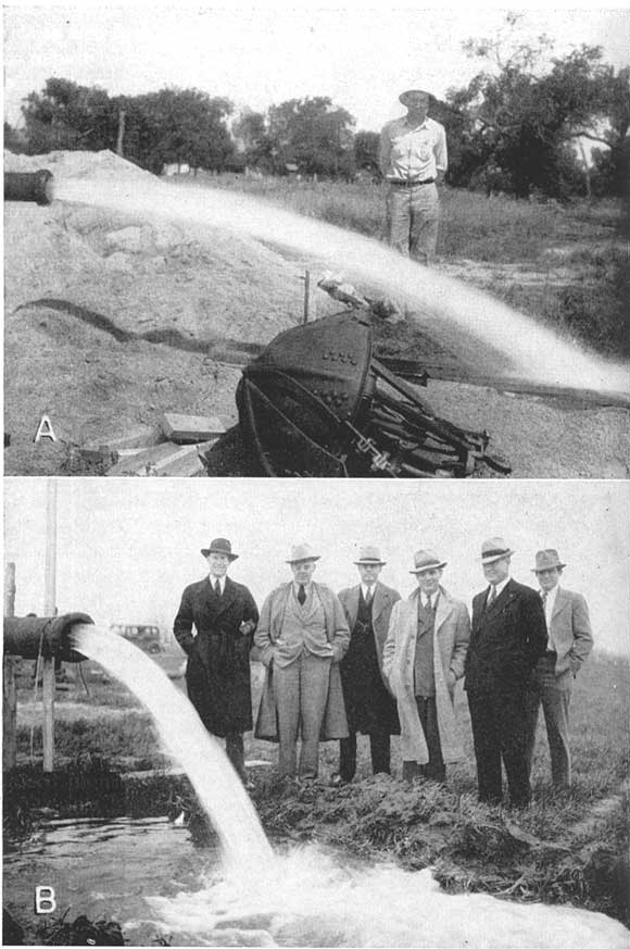
Table 8.--Transmissibility (a), permeability, and specific capacity of the new Wichita supply wells.
| Well No. | Saturated thickness of water-bearing material (feet) |
Specific capacity (gallons a minute per foot of drawdown) |
Coefficient of transmissibility |
Average coefficient of permeability |
|---|---|---|---|---|
| 311 | 205 | 27.5 | 46,000 | 224 |
| 314 | 212 | 22.6 | 52,800 | 249 |
| 317 | 209 | 32.2 | 62,100 | 297 |
| 322 | 210 | 14.6 | 52,600 | 250 |
| 330 | 216 | 24.4 | 68,700 | 318 |
| 333 | 235 | 29.5 | 100,400 | 427 |
| 415 | 239 | 20.2 | 73,300 | 307 |
| 419 | 246 | 24.5 | 85,600 | 348 |
| 423 | 231 | 42.2 | 190,000 | 822 |
| 426 | 230 | 32.9 | 127,000 | 553 |
| 429 | 216 | 56.8 | 261,000 | 1210 |
| 433 | 179 | 53.5 | 110,000 | 614 |
| 436 | 222 | 49.3 | 87,500 | 394 |
| 440 | 178 | 40.5 | 66,000 | 371 |
| 450 | 90 (b) | 54.9 | 223,000 | |
| 452 | 176 | 38.9 | 92,400 | 525 |
| 455 | 108 (b) | 141.0 | 330,000 | |
| 459 | 233 | 47.4 | 123,500 | 530 |
| 465 | 145 | 42.8 | 67,600 | 467 |
| 473 | 65 (b) | 90.7 | 278,000 | |
| 476 | 66 (b) | 34.3 | 198,000 | |
| 479 | 133 | 32.0 | 63,500 | 478 |
| 487 | 190 | 34.0 | 75,700 | 398 |
| 491 | 83 (b) | 56.4 | 154,200 | |
| 494 | 176 | 45.8 | 123,000 | 690 |
| (a) Determined by the Theis recovery method. | ||||
| (b) Well does not penetrate entire aquifer. | ||||
Thiem method.--The Thiem method of determining the permeability of a water-bearing material consists of analysis of the decline in water level during the pumping period in a pumping well and in several observation wells near the pumping well. The method is based on the consideration that after approximate equilibrium is established around a pumped well, approximately equal quantities of water move toward the well in a given unit of time through a successive series of concentric cylindrical sections around the well. Because the areas of the large cylinders through which the water percolates are greater than the areas of the smaller cylinders, the velocity of the ground water passing through the larger cylinder is proportionately less and the hydraulic gradients are proportionately smaller.
The derivation of the general Thiem formula has been discussed by Wenzel (1942, p. 77-81). V. C. Fishel has developed a very convenient formula for determining the permeability of water-bearing material by the Thiem method:
P = (527.7 q / m) • (Δ log10 r) / Δh
in which P = coefficient of permeability (as defined above), q = discharge of the pumped well in gallons a minute, m = average saturated thickness of the water-bearing material at the observation wells after the water table has declined to an approximate equilibrium condition, r = distance of observation wells from the pumped well, in feet, h = altitude of the water table at the observation wells.
The value of the member Δlog10 r / Δh is obtained by making use of the straight-line relationship that exists when the altitudes of the water levels in the observation wells are plotted on a natural scale against the distances of the observation wells from the pumped well on a logarithmic scale, and its value is given by the slope of the straight line.
Pumping test.--A pumping test was made in 1937 to determine the permeability of the water-bearing sand and gravel in the Arkansas River valley at well 608, about 3 miles north of Wichita on the property of and with the full cooperation of the Kansas Gas and Electric Company (Pl. 26). The well is 20 inches in diameter and 45.3 feet deep. The thickness of the saturated water-bearing material just before the test was 26.8 feet. Observation wells were constructed at varying distances on four radial lines extending north, east, south, and west from the pumped well and were located as shown in Figure 10. All the observation wells and the pumped well penetrated the full thickness of the aquifer. Well 608 was operated continuously at a rate of 1,000 gallons a minute from 10:33 a.m., November 8, to the afternoon of November 27, at which time the pump was unavoidably stopped. Pumping was resumed on November 28 at a rate of 750 gallons a minute and was discontinued December 8 at 9:55 a.m.
Plate 26A--Well (608) of Kansas Gas and Electric Company discharging 1,000 gallons a minute into Little Arkansas River during 19-day pumping test. Photograph by S. W. Lohman.
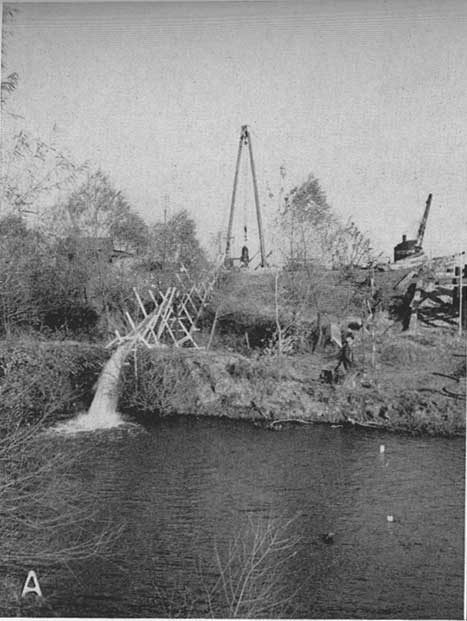
Plate 26B--Bipod and orange-peel bucket used in construction of well 609. Photograph by S. W. Lohman.
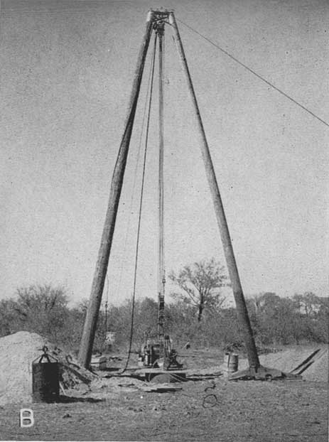
Figure 10--Map showing the location of well 608 and the nearby observation wells of the Kansas Gas and Electric Company, sec. 29, T. 26 S., R. 1 E.
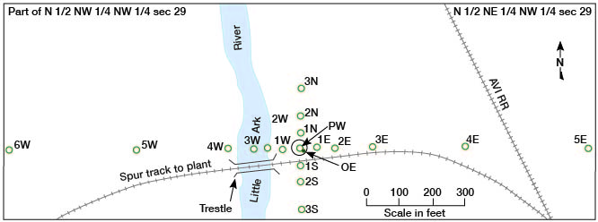
The locations and depths of the observation wells, the altitudes of the static water levels on November 8, the equilibrium pumping levels, and the drawdowns on November 26 are given in Table 9.
Table 9--Water level data collected during a pumping test at well 608.
| Well No. and direction from pumped well |
Distance from pumped well (feet) |
Altitude of water levels | Drawdown (feet) | |
|---|---|---|---|---|
| Static level Nov. 8, 10:30 a.m. (feet) |
Pumping level Nov. 26 (a) (feet) | |||
| 1N | 49.2 | 1,309.62 | 1,303.76 | 5.86 |
| 2N | 100.7 | 1,309.75 | 1,305.17 | 4.58 |
| 3N | 189.4 | 1,309.91 | 1,306.55 | (b) 3.36 |
| 1S | 49.0 | 1,309.52 | 1,304.10 | 5.42 |
| 2S | 100.4 | 1,309.58 | 1,305.37 | 4.21 |
| 3S | 190.0 | 1,309.48 | 1,306.34 | 3.14 |
| 1E | 49.3 | 1,309.67 | 1,303.62 | 6.05 |
| 2E | 101.3 | 1,309.68 | 1,304.94 | 4.74 |
| 3E | 220.9 | 1,309.73 | 1,306.62 | 3.11 |
| 4E | 500.1 | 1,309.88 | 1,307.97 | 1.91 |
| 5E | 900.1 | 1,309.99 | 1,308.87 | 1.12 |
| 1W | 49.3 | 1,309.55 | 1,304.22 | 5.33 |
| 2W | 100.5 | 1,309.53 | 1,305.43 | 4.10 |
| 3W | 139.7 | 1,309.43 | 1,305.98 | 3.45 |
| 4W | 222.3 | 1,309.52 | 1,307.13 | 2.39 |
| 5W | 503.5 | 1,309.43 | 1,308.10 | 1.33 |
| 6W | 895.0 | 1,309.63 | 1,308.69 | 0.94 |
| OE | 3.2 (c) | 1,309.62 | 1,296.90 | 12.72 |
| PW (d) | 0.0 | 1,309.60 | 1,294.70 | 14.90 |
| (a) Average of two measurements made on Nov. 26. | ||||
| (b) Interpolated. | ||||
| (c) Measured from center of pumped well (PW), situated just outside of gravel packing. | ||||
| (d) Pumped well. | ||||
In Figure 11 the altitudes of the water levels on November 26, 1937, for each line of wells are plotted against the distance of the observation wells from the pumped well. The altitudes of the water levels for r at distances of 10 and 100 feet were obtained from the straight line curves (Fig. 11) and are given in Table 10. The pumping rate was 1,000 gallons a minute and the average saturated thickness in the cone of depression was about 22.2 feet. The equation becomes
P = [(527.7 • 1,000 )/ 22.2] • (Δ log10 r / Δ h).
The term Δ log10 r is 1 when r2 and r1 are 100 and 10 feet respectively, thus (Δ log10 r / Δ h) is equal to 1 divided by the difference in altitude of the water levels at 10 and 100 feet respectively from the pumped well. The permeability as computed for each line of observation wells is given in Table 10.
Figure 11--Altitude of water levels just before pumping stopped on November 26, 1937, plotted against the distance of the observation wells from pumped well 608.
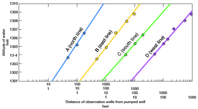
Table 10.--Computations of the coefficient of permeability by the Thiem method at well 608.
| Direction of observation wells from pumped well |
Altitude of water level at r = 10 feet (feet) |
Altitude of water level at r = 100 feet (feet) |
Δlog10 r | Δh (feet) | Coefficient of permeability |
|---|---|---|---|---|---|
| North | 1,300.30 | 1,305.26 | 1 | 4.96 | 4,795 |
| East | 1,300.65 | 1,304.95 | 1 | 4.30 | 5,528 |
| South | 1,301.50 | 1,305.32 | 1 | 3.82 | 6,223 |
| West | 1,301.60 | 1,305.43 | 1 | 3.83 | 6,206 |
| Average of north-south lines | 5,509 | ||||
| Average of east-west lines | 5,867 | ||||
| Average of all lines | 5,688 | ||||
The Thiem method could not be used satisfactorily in determining permeability from pumping tests of the new Wichita municipal supply wells because observation wells were too few and did not penetrate the entire aquifer.
Specific Capacity
The specific capacity of a well may be expressed as the number of gallons a minute that a well will yield for each foot of drawdown. It has been found experimentally that this relationship does not hold precisely except for the first few feet of drawdown and that it often fails because of differences in construction and development of wells. Comparison of the specific capacities of wells is useful, however, in estimating relative efficiency of wells and permeability of formations. The specific capacities of the 25 Wichita city wells (Tables 8 and 32) range from 14.3 at well 322 to 141 at well 455, and it is noted that the largest specific capacity and the largest coefficient of transmissibility occur for the same well (see Table 32 for pumping rates during the 36-hour tests).
The specific capacities of other wells in the area of this investigation are given in the remarks column in Table 37.
Prev Page--Geologic History || Next Page--Fluctuations of Water Table
Kansas Geological Survey, South-central Kansas
Comments to webadmin@kgs.ku.edu
Web version April 2005. Original publication date July 1949.
URL=http://www.kgs.ku.edu/Publications/Bulletins/79/09_groundwater.html