Introduction
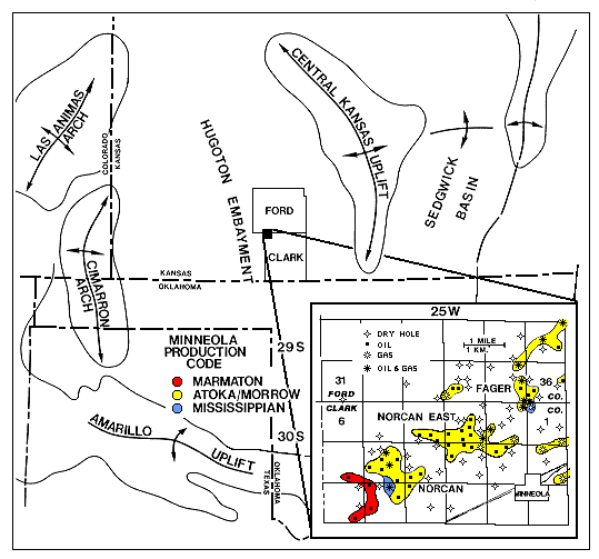
A reflection seismic experiment was conducted over the Minneola complex
of oil and gas fields in Clark county, southwest Kansas (Fig.
1) in an attempt to acquire high-resolution data that might
distinguish a Morrowan-Atokan clastic section containing thin productive
sandstones near the top of a channel fill to estuarine/marine section, from
one that does not contain these sandstones (Fig.
2). The specific fields studied during this project are the Norcan and
Norcan East fields (Fig. 1). Previous seismic
data acquired in the area suggest that generally southwest-northeast trending
channels up to 86 ft deep or more incised into underlying Mississippian
limestones are imaged as a high amplitude trough surrounded by high amplitude
peaks compared to the much lower amplitude reflection at the same level
when a channel is not present (Clark 1987, 1995). Diffractions, and sometimes
faults in the underlying Mississippian limestones also help outline the
margins of the channels. Unlike typical channel sandstones, though, the
productive sandstones at in the Minneola complex occur near the top of the
basal clastic section (Fig. 2) and are more likely
associated with a marine barrier bar or estuarine facies that is thicker
in the channels, possibly due to compaction of the shales or lower bathymetry.
These sands have been interpreted to occur in a series of northwest-southeast
trending bars, separated by shales (Clark 1987, 1995). Because of this,
numerous wells that have been drilled in the deeper channels and have encountered
only shale or only very thin (few feet) unproductive sandstones. Because
the productive sandstones are still not very thick (maximum gross in the
project area is 15 ft), previous lower frequency seismic data was unaffected
by the presence or absence of the sands. Therefore a drilling program could
only be based on geology and the seismicly defined channels.
in an attempt to acquire high-resolution data that might
distinguish a Morrowan-Atokan clastic section containing thin productive
sandstones near the top of a channel fill to estuarine/marine section, from
one that does not contain these sandstones (Fig.
2). The specific fields studied during this project are the Norcan and
Norcan East fields (Fig. 1). Previous seismic
data acquired in the area suggest that generally southwest-northeast trending
channels up to 86 ft deep or more incised into underlying Mississippian
limestones are imaged as a high amplitude trough surrounded by high amplitude
peaks compared to the much lower amplitude reflection at the same level
when a channel is not present (Clark 1987, 1995). Diffractions, and sometimes
faults in the underlying Mississippian limestones also help outline the
margins of the channels. Unlike typical channel sandstones, though, the
productive sandstones at in the Minneola complex occur near the top of the
basal clastic section (Fig. 2) and are more likely
associated with a marine barrier bar or estuarine facies that is thicker
in the channels, possibly due to compaction of the shales or lower bathymetry.
These sands have been interpreted to occur in a series of northwest-southeast
trending bars, separated by shales (Clark 1987, 1995). Because of this,
numerous wells that have been drilled in the deeper channels and have encountered
only shale or only very thin (few feet) unproductive sandstones. Because
the productive sandstones are still not very thick (maximum gross in the
project area is 15 ft), previous lower frequency seismic data was unaffected
by the presence or absence of the sands. Therefore a drilling program could
only be based on geology and the seismicly defined channels.
The purpose of this project was to determine if a seismic technique designed
to acquire high-frequency data could be used in the Minneola area to define
channels with thicker, productive sands from those that contained only thin,
non-productive sands, or no sands at all. To accomplish this goal, three
lines were laid out: One along a major seismicly and geologically defined
channel, the other two across several channels (Figs. 3,
4, 5, 6,
7, 8). These lines
also crossed areas with the productive upper sandstones in the channels
and areas with no sand in the channels (Figs. 9,10,11).
e-mail : webadmin@kgs.ku.edu
Updated January 1999
The URL for this page is http://www.kgs.ku.edu/PRS/publication/OFR98_44/intro.html