![]()
Prev Page--Introduction and Study Area || Next Page--Results
Chapter 3--Relevance, Methodology, and Related Research
Background
Because of the established relationship of water-well construction and siting to ground-water contamination, attempts were made to develop uniform well-construction standards nation-wide as early as 1948 (Hudson, 1948). These were not successful until 1965 when the water Well Construction and Pump Installation Act was passed (Humes, 1966). This model law provided a framework under which states could develop regulations to assure safe and adequate supplies of potable water.
At the time, however, Kansas did not take advantage of the model law, but instead issued the "Manual of Recommended Practice for Locating, Constructing, and Equipping water Wells for Rural Homes," (Shull and Jackson, 1965), through its then State Department of Health. It was not until after the passage of the Federal Clean water Act in 1972 that Kansas passed the Groundwater Exploration and Protection Act that established minimum water-well construction standards and provided for the licensing of water-well contractors and the submission of hydrogeologic data to the State (Kansas Statutes, 1973).
Since 1974 a yearly average of 4,OOO water wells have been constructed or reconstructed and reported in Kansas to at least meet the minimum standards. Approximately 1,100 of these wells were for domestic use in 1985 (Plummer, 1986). Some of these minimum construction standards (Kansas Administrative Regulations, 1974) include use of approved casing and grouting materials, grouting the top 10 ft of the annular space of the well between the casing and the borehole (which is required to be a minimum of three inches larger in diameter than the casing in order to effectively place the grout material), and proper siting distance from potential pollution sources. These regulations greatly improved standards of construction for water wells in Kansas.
Hydrographs from the two domestic water wells used as monitoring wells in the previous Marion County study (O'Connor et al., in preparation) showed that despite each supposedly being constructed to meet minimum well-construction standards and each tapping a confined carbonate aquifer, the water quality and water levels in well L10, located in Lincolnville, fluctuated significantly and relatively rapidly compared to well #31 (Fig. 1), located on a farm six miles noth.
According to information submitted by the contractor on the water-well record (Appendix II), the town well (L10), had been drilled to a depth of 115 ft and was grouted in the annular space from 2.5 ft to 17 ft, which is 4.5 ft more than the required minimum of 10 ft (see Figure 11). It should be noted that although the contractor only reported a 6 inch borehole on the WWC-5 Form (which would allow only a one inch annular space the total length of the well), it is believed that the contractor did drill a larger diameter borehole, probably 10 inch, in the upper 10 to 15 feet of well L10, but merely failed to report it on the WWC-5 Form. This is concluded after studying the other forms for domestic water wells constructed in the study area by the same water-well contractor during the same time period, on which he consistently reported a larger diameter borehole in the upper 10 or 15 ft. Therefore, the minimum requirement of a 3-inch annular space in the grouted interval from 2.5 ft to 10 or 15 ft probably was met.
Figure 11--Representation of construction details of well L10 (drilled January 12, 1979).
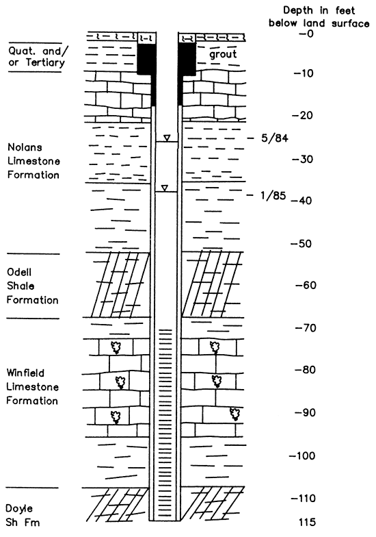
The 12 ft of limestone from 9 to 21 ft in the driller's log is most likely the Herington Limestone Member of the Nolans Limestone. The 'clay' and 'shale' intervals from 21 to 52 ft probably represent at least the remainder of the Nolans Limestone and possibly some of the Odell Formation, of which the red shale interval from 52 to 67 ft is definitely a part. The 5 ft of light brown 'shale' from 67 to 72 ft could be either a part of the lower Odell Shale or the upper Cresswell Limestone Member of the Winfield Limestone.
It is not possible to assign exact boundaries between Members and formations based on the generalized nature of the lithologic log provided by the contractor. However, it is important to point out that possibly as much as 51 ft of 'clay' and 'shale' separate known water-bearing limestone beds in the Nolans and the Winfield formations, thus acting as a confining bed or aquitard above Lincolnville's water supply, the Winfield aquifer.
Because of the extent of solution-cavity formation or solution permeability observed at outcrops and during drilling and coring of the Herington Limestone Member (Appendix I), its close proximity to the ground surface, and reports of ground-water seepage near its base, it is believed that the Herington is capable of yielding significant quantities of ground water during the period from late winter through early summer when snow is melting, frost has left the ground, precipitation is increasing, and evapotranspiration is still relatively low.
The Herington probably becomes an unconfined aquifer in parts of the study area during this period. The water table that forms would possess a higher hydraulic head than that of the Winfield aquifer. In well L10 (Fig. 11), the hydrauliC head of the Herington Limestone would have been between 9 and 21 ft. The static water level in well L10 fluctuated between 24 and 38 ft below ground surface during the previous county study (O'Connor et al., in preparation), This difference in hydraulic head and the fact that the annular space in well L10 was not grouted below 17 ft, therefore not completely sealing out the entire thickness of the Herington Limestone, would result in the downward movement of ground water in the annular space from the Herington to the Winfield Limestone aquifer. This phenomenon, termed hydraulic interconnection (O'Connor, 1982), would explain the seasonal trend observed in the hydrographs for this well where recharge appeared as rapid and significant water-level and water-quality fluctuations, causing the confined Winfield aquifer to resemble a shallow, unconfined aquifer highly susceptible to recharge and potential pollution.
Relevance
Because of the seasonal potential for pollution inferred from the hydrographs for a well in a town that obtains its water supply solely from private, domestic water wells, it was desirable that the magnitude and extent of the water-quality variability and possibly contamination be determined in Lincolnville.
In addition, the extensive use of domestic water wells in the study area made it necessary to evaluate water-well construction methods utilized both before and after standards were established to determine the effect of the minimum construction standards on ground-water quality.
While a great number of case histories and studies have shown that certain factors of water-well construction and completion can result in contamination of domestic ground-water supplies, these factors are usually typical of older water wells constructed before the establishment of any well construction standards. However, little research has been dedicated to the evaluation of the effectiveness of the minimum standards to provide domestic ground-water supplies that are safe for drinking, especially in Kansas.
The hydrogeologic setting in the study area, consisting of consolidated bedrock strata and a confined aquifer system, is typical of the eastern one-third of the State. Thus, results of this research are applicable to an extensive number of wells and beneficial to a large number of people including water-well users and contractors, regulatory agencies, and public-health officials.
Although the main objective of the study was concerned with the construction details of domestic water wells and their resulting effect on ground-water quality, an important indirect concern was the public-health aspects of the ground-water quality. Therefore, nitrate and fecal bacteria concentrations, for which primary drinking water standards exist, were monitored in the study. Determination of these concentrations is standard in Kansas in the evaluation of potable water. Total organic carbon (TOC), measured as volatile and nonvolatile organic carbon (VOC and NVOC) concentrations, were also measured in ground-water samples from the water wells. Since VOC's are human-made chemicals and do not occur naturally (with the exception of the gas methane), their presence would be an indication of anthropogenic contamination. Although NVOC's can have either a human-made or natural source, their presence was not expected in a confined carbonate aquifer unless water from the ground surface or the unsaturated soil zone carrying them was able to enter the confined aquifer. Monitoring for chloride concentration and specific conductance was continued because secondary or recommended drinking water standards, exist for chloride and total-dissolved-solids (TDS) contents. The TDS of a water can be estimated by multiplying the specific conductance by a constant applicable for the area.
Methodology
In order to fulfill the objectives of the study, an investigation of water wells was initiated in and around Lincolnville, Kansas. Ground-water quality was monitored both in wells constructed prior to the establishment of minimum construction standards (pre-1974) and those constructed since 1974 and supposedly meeting minimum standards.
Water levels were measured in some wells, if convenient, on a monthly basis and in others on a less regular basis. Water-level measurements were made prior to pump age of the well and collection of the ground-water sample so as to obtain a water level as near static conditions as possible. However, since prior pumpage of these wells could not be controlled completely during the study, some of the measurements represented recovering water levels.
A time-series sampling program was used to try and reproduce the seasonal trend observed in the Lincolnville monitoring well from the previous county study (O'Connor et al., in preparation), and to monitor water-quality constituents related to public health and potential pollution sources.
At least 118 water wells are believed to exist in the study area. Undoubtedly more exist but were not reported or readily identifiable and are most likely old abandoned wells which may or may not be properly plugged.
Twenty wells were inventoried during the latter part of July and early part of August 1984. All but one were in Lincolnville. The inventory involved obtaining information about the well from the owner or user and included materials used in and details of the well construction, total depth and date drilled, water-well contractor, servicing or maintenance, type of pump used, lithology and aquifer material (if known), and past or present activities in the vicinity that had or could have resulted in contamination of the well. In addition, any historical data available for the well were obtained such as previous measurements of static water level, well yield, and water-quality constituents. Finally, verbal descriptions of the quality and quantity of water produced by the well were obtained from the well owner or user. Sketches of each well inventoried and its surroundings were made and in many cases print and slide photographs were taken.
Data from these wells were reviewed in order to select the monitoring wells from which to collect a suite of ground-water samples twice during the one-year study. Because of a limited project budget only eight wells were used as the primary monitoring wells. The samples collected from these wells were analyzed for fecal coliform and fecal Streptococcus bacteria, total organic carbon (TOC) as volatile and nonvolatile organic carbon (VOC and NVOC), the dissolved gases methane, oxygen, and carbon dioxide, and standard inorganic chemistry.
One of the sample collections from the monitoring wells was made in May of 1985 (TOC and standard inorganic chemistry on May 8th; and bacteria and samples for analysis of chloride, nitrate, and specific conductance on May 20th and 23rd) during a period when chloride concentrations and specific conductance as well as water levels had been quite high in well L10 from the previous county study (Fig. 1). The second sample collection was made during the period from mid-summer to late winter which was represented in well L10 hydrographs by lower and relatively stable constituent concentrations and water levels (TOC - August 1985, standard inorganic chemistry - September 1984, and fecal bacteria - December 1984).
The monitoring wells were, however, monitored monthly for chloride and nitrate concentrations and specific conductance using in-field testing equipment which was convenient and inexpensive. Nitrate analysis did not begin until November 1984 due to a delay in shipping of the equipment.
Because of the convenience of the in-field testing equipment, some additional wells were monitored for chloride and nitrate concentration and specific conductance. In addition, the interest and cooperation expressed by many of the townspeople made it possible to include wells that allowed better areal coverage and the opportunity to monitor sites of known or suspected ground-water pollution in the study area.
In all, 14 additional wells were sampled at least twice during the one-year program. Figure 2 shows the locations of the wells used in the study and the frequency with which they were sampled. Three wells in the study area which had been inventoried in the previous county study were included in this project.
Although pumping rate, scheduling, and sampling procedure have been shown in the literature to be important in a water-quality investigation involving water or monitoring wells, several additional factors had to be considered in the design of this study. First, the wells used in the project were existing domestic water wells that were in current use.
The average daily domestic use per person of ground water has been estimated to be 50 to 75 gallons per day (gpd) (U.S. Environmental Protection Agency, 1982). For most of the wells in the study area this average volume equals or nearly equals one well-bore volume, traditionally the minimum amount of water pumped out of monitoring wells before ground-water samples are collected for chemical analysis. In wells where the borehole diameter was known to be larger than the casing diameter and no grout had been placed in the annular space opposite the static or pumped water levels, an amount of ground water equal to the larger borehole volume should be expelled before a sample is collected. The borehole volume for the wells in the study area was generally a little more than one to as much as four times more than the average daily use per person. However, since the average number of persons per household studied in Lincolnville was 2.4 for domestic wells used year-round, then at least one well-bore and in most cases one borehole volume of ground water was pumped from each well on a daily basis.
In most cases, wells were pumped until the groundwater temperatures stabilized near the typical range for ground water in Marion County, 54 to 59 degrees Fahrenheit (12.2 to 15.0 degrees Celsius), before samples were collected (usually after at least 5 minutes of pumping). Temperatures above or below this range usually indicated water which had been stored somewhere in the piping system and been affected by air or shallow ground temperatures. Specific details as to method of sample collection and storage, and analytical methods and results are presented in Appendices V and VI.
Several duplicate samples were collected and analyzed for nitrate concentration in order to estimate the analytical error of the in-field testing equipment. The duplicates were analyzed by the Analytical Services Section of the Kansas Geological Survey. The estimated accuracy of the method utilized by them was 4 percent or less. The difference in nitrate concentrations determined by the two methods ranged from 4 to 27 percent with the average difference being 16 percent. The greater percent differences were associated with longer holding times of some samples before nitrate analysis could be performed using the in-field testing equipment. Because samples analyzed using the in-field testing equipment were not preserved at time of collection, nitrate values reported were consistently lower than those obtained by the Analytical Services Section.
The estimated analytical error of the chloride concentrations determined by the in-field testing equipment was 4 percent and was based on repeated determinations of standards during each set of samples. That for specific conductance was approximately 2 percent.
Related Research
Proper well construction for sanitary well-water supplies has been advocated by many in the water well industry literature over the years (Bennison, 1947; DeFrain, 1949; Fawcett, 1949; McEllhiney, 1955; Guardino, 1964; Campbell and Lehr, 1973; U.S. EPA, 1975; American Water Works Association, 1985; and Driscoll, 1986).
In 1983, Chaffee and O'Connor advocated the use of additional grouting material in the annular space of gravel-packed water wells, a popular method of well construction in Kansas, beyond the State's minimum requirement of 10 ft near the ground surface. The recommendation was made to further assure protection of the aquifer both during the use of the well and after its abandonment and plugging.
Considerable reference in the literature has been made to ground-water contamination as it relates to improper or inadequate construction or abandonment and nonplugging of water wells (Williams, 1948; Vogt, 1961; Deutsch, 1965; Jorgensen, 1968; Anonymous, 1970; Ham, 1971; McDermott, 1971; and Jones, 1971).
More recently, Exner and Spalding (1985), studied water wells used for households and livestock-watering in southeast Nebraska. Of the total 268 wells studied, 71 percent exceeded 10 mg/L nitrate-nitrogen (NO3-N) and total coliform (TC) bacteria density of 1 per 100 mL of sample. Only 10 percent of the total met Nebraska's criteria for private well construction, and of these, 4 percent had greater than 10 mg/L NO3-N and 30 percent had a TC greater than or equal to 1 count/100 mL. The most common inadequacies of the wells not meeting the construction criteria were location too near a source of nitrate and location in a pump pit or depression where ponding of surface water occurred, and a lack of watertight casing, well cap, and/or grout seal in the annular space.
The water-quality study of Kansas farmstead wells conducted in 1985 and 1986 attempted to assess the quality of water produced by private farmstead wells (Heiman et al., 1987). Of 103 wells tested, eight and two had detectable amounts of pesticides and VOC, respectively, and 38 wells had concentrations of one or more inorganic constituents exceeding Maximum Contaminant Levels (MCL's) established by the U.S. EPA (1984). These wells included both those constructed before and since regulations governing the minimum well-construction standards had been established for private wells in Kansas in 1974.
Pettyjohn (1976, 1982), discussed the effects of recharge events in humid areas on seasonal changes in ground-water quality. During the spring recharge period large quantities of water soluble substances are leached from storage in the unsaturated zone to the water table causing significant changes in ground-water quality. Therefore, the major influx of contaminants to a shallow aquifer can occur on an annual basis. In the summer months, the potential for rapid, but localized changes in ground-water quality exists because large and abundant macropores and fractures can allow considerable groundwater recharge.
Keith et al. (1983), discussed not only the various sources of temporal-spatial variability in ground-water-quality data but also methods of controlling or accommodating the sources of variability. They grouped the sources into three general categories: 1) variability due to the impact of land use upon ground-water quality; 2) variability due to the well-vadose zone-aquifer system--specifically well construction, pumping rates and schedules, geology, hydraulic conditions at the sample site, and physical-chemical processes in the well bore, vadose zone and aquifer; and 3) variability due to sampling and analysis.
In regional monitoring programs in which existing production wells were utilized, they considered the major well-construction parameters of concern to be the perforated interval and the annular seal. Of special interest were cases where the perforated interval Cor gravel pack or open annulus hydraulically connected with perforations) intercepted more than one aquifer. In these cases, one could expect an exchange of water between various strata in perched, water-table, and confined aquifers while the well was not pumping due to vertical hydraulic gradients. The contribution of water from each stratum could vary with time when the well was pumped.
Keely (1982) has shown that the patterns of arrivals of contaminants as a function of pumpage, obtained from chemical time-series sampling of monitoring wells, can be used to interpret the locations of contaminant sources and plumes.
Wilson and Rouse (1983), caution that over-pumping of a monitoring well installed in a complex hydrologic regime can result in mixing of waters of different quality and, in the extreme case, contamination of noncontaminated aquifers by previously localized or stratified pollutants. In addition, too high a rate of pumpage or extended pumpage, resulting in a large cone of depression, can also result in mixing of aquifer waters or induce leakage.
Graphical techniques were used by Allen and Walker (1984) to identify monitoring parameters that exhibited temporal variation. They found that temporal variation of ground-water quality is apparent in monitoring wells sampled quarterly for as few as two years. Parameters that exhibited temporal variation included pH, conductivity, TOC, chloride, sodium, sulfate, iron, and calcium. The first four were closely correlated with seasonal changes. They also found that the amplitude and frequency of fluctuations in ground-water quality are lower in confined ground water aquifers and in relatively impervious strata such as clays and bedrock compared with sands and till. Furthermore, that the frequency of these fluctuations did not appear to correlate with seasonal changes.
Schmidt (1977) also used graphical techniques and water-quality data from large-capacity wells to define short-term, seasonal, and long-term trends in well-water quality (versus ground-water quality). He found that changes in water quality after a few minutes or hours of pumping are often related to pump operation. Large fluctuations over short time periods can occur when wells are constructed so as to draw water directly from the strata nearest the water table in developed areas and when wells are close to point or line sources of recharge or pollution, particularly in cases where large volumes of recharge or high pollutant loads are involved. Schmidt determined that seasonal changes in well-water quality were related primarily to (1) pumping patterns, (2) variations in the magnitude and quality of recharge from point or line sources, and (3) amount and quality of water reaching the water table from the vadose zone.
Contamination of ground water with nitrate is a concern because of the known connection between infant methemoglobinemia (also known as cyanosis or "blue baby syndrome") and high nitrate concentrations in drinking water. Nitrate is not the causative agent, but is converted by intestinal bacteria into nitrite which lessen the oxygen carrying capacity of the blood, sometimes to the point of death. Infants below three months of age and young animals are extremely susceptible to high levels of nitrate poisoning (Ronnebaum, 1987). In 1984 the U.S. EPA established an MCL of 10 mg/L for NO3-N, or 45 mg/L as NO3.
Several studies have shown nitrate concentration in ground water to exhibit seasonal trends, generally increasing during periods of increasing precipitation, and also short-term variations in shallow wells. Some of these studies also established an inverse relationship between nitrate concentration and well depth and/or depth of well casing or casing perforations (Crabtree, 1972; Walker, 1973; Piskin, 1973; Tryon, 1976; Schmidt, 1977; Spruill, 1983).
Chapter 4--Water-well Construction Methods Utilized in Lincolnville
General
It has been reported (A. Riffel, 1984, verbal comm.), that very early in Lincolnville's history shallow dug and later drilled wells obtained ground water from the Nolans Limestone. As the town grew and the number of wells increased, the Nolans became a less reliable source of water supply and subsequent wells were drilled to the Cresswell Limestone Member, the upper member of the Winfield Limestone. In the mid-1950's during a five-year drought, existing wells again were deepened or new ones drilled to greater depths. This time the wells tapped an aquifer in the lower part of the formation, the Stovall Limestone Member or the Gage Shale Member in the upper part of the Doyle Shale. It was reported that a few wells went even deeper to the "big water" which is believed to be the Towanda Limestone Member of the Doyle Formation.
The older drilled wells (pre-1974), represent construction and completion methods utilized in Lincolnville before minimum·well-construction standards were established. Many of these methods were no longer allowed under the rules and regulations passed in 1974 which governed such items as materials used for casing, screening, and grouting, grouted interval in the annular space, watertight joints in the casing, distance from potential source of pollution or contamination, licensing of water-well contractors, and well abandonment and plugging; etc.
Water-well records (WWC-5 Forms) for post-1974 wells are presented in Appendix II. All available information concerning the construction details of the pre-1974 wells used in the study is presented in Appendix III.
Pre-1974 Water-Well Construction
Any of the large-diameter, shallow dug wells that were common early in Lincolnville's history have long since been filled-in and/or covered over and can no longer be identified. However, many of the older drilled wells still exist, several of which are still in use. The older drilled wells were usually constructed using a cable tool or percussion-type drill rig. They were cased with heavy wrought iron and/or light-weight galvanized steel. The latter type of casing was generally thin-walled (O.062 inch) and especially susceptible to corrosion. In addition, galvanized steel casing had screw-type joints at 4 or 5 ft intervals which leaked.
According to the late Arnold Riffel, a water-well contractor from Lincolnville, he or his father constructed or reconstructed many of the wells in and around the study area from the 1940's to the early 1970's. Reconstruction involved replacing the old casing and sometimes included deepening the well several feet to obtain a more adequate water supply.
Mr. Riffel commonly constructed or reconstructed his wells with both heavy iron and galvanized steel casing. He usually would use a 10 or 20 ft segment of the iron casing at the top of a well to protect the thinner (typically 1/16 or 0.062 inch), galvanized steel casing from the corrosive effects of shallow soil water in the weathered zone. The surface casing protected the well from the otherwise eventual entrance of shallow water potentially carrying bacteria and contaminants.
In a few cases where pollution from a gasoline spill had affected nearby water wells or where additional protection from surface contamination was desired, Riffel installed longer sections of the iron surface casing. For example, in his own well he installed 50 ft of surface casing and in well L22, located on a farm one-half mile east of town, he reportedly recased the well to 30 ft.
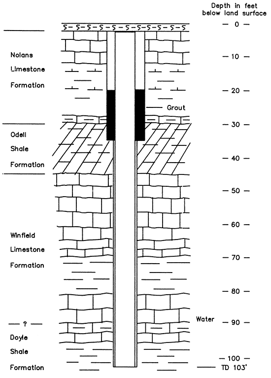
Another local water-well contractor was recalled to well L17 soon after he had constructed it in the early 1970's because the water produced by the well contained a petroleum fuel product from a former nearby fuel spill. The contractor reconstructed the well and grouted the annular space to a depth of 35 ft and the problem was corrected (P. Backhus, 1985, written comm.) (Fig. 12).
Figure 12--Representation of reconstruction details of well L17 (1973). Geology based on driller's logs of nearby wells.
Mr. Riffel began grouting the annular space around surface casing in his water wells in the early 1950's. For grout he used either cement, drilling mud, or dirt and drill cuttings. If the surface casing was to be installed in shale, he merely 'drove' it into the borehole with his cable-tool rig.
Traditional slotted screen was not used in bedrock wells in this part of the State, Riffel claimed. Instead he and other drillers perforated the galvanized steel casing with holes adjacent to the water-bearing zone(s). In some cases where large intervals of limestone were encountered during drilling, some drillers would not install any casing. This method was referred to as 'open-hole' construction.
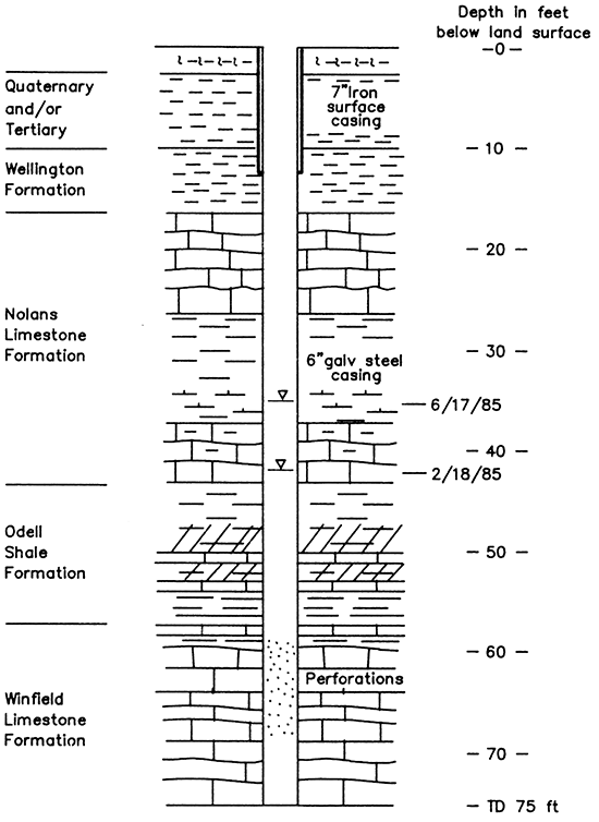
Records kept by Riffel on wells that he or his father constructed or reconstructed showed the well owner, date drilled, total depth, and footage of galvanized steel casing installed. Because he did not charge for the iron surface casing or its installation, very few records were kept for these wells as to the length of surface casing used or whether it was grouted or driven into place. Figure 13 is a hypothetical representation of well L5 which was reconstructed by Riffel in 1953. His records showed that he recased the well with 12 ft of iron surface and 7S ft of galvanized steel casings. The geological information was extrapolated from driller's logs from water well records for two nearby wells.
Figure 13--Representation of reconstruction details of well L5 (recased 1953). Geology based on driller's logs of nearby wells.
In one case, well L3, the original homeowner needed a water well but because of financial difficulties requested that Riffel construct the well as inexpensively as possible. Therefore, Riffel drilled a well about 90 ft deep, installed 2S ft of iron surface casing, and left the rest of the hole open.
Several wells in Lincolnville were constructed by other local drillers mostly in the late 1960's and early 1970's at a time when drilling by Riffel slowed down considerably owing to health problems. It was during this period that plastic casing was becoming popular and fewer wells were completed using heavy-steel surface casing.
At the same time, some advances in equipment used in water-well completion were introduced into the area. The equipment included the pitless well adaptor and unit, and the sanitary well seal (Pritz, 1986, verbal comm.). Although these offered much needed sanitary protection to the water well, their use was strictly optional and did not gain great popularity until after the establishment of well-construction regulations in 1974.
Before the introduction of the pitless well adaptor and sanitary well seal, well-completion methods used in Lincolnville left a great deal to be desired. In most cases water wells were constructed by the drilling contractor and then completed by a pump installer or plumber. Some of the methods used to complete the installation of a water well included a well pit, underground completion, and above-ground completion in well houses. These three types of completion have been shown to allow the entrance of contaminants into the well under certain conditions. The well pit has been cited as the most notorious for allowing shallow surface water to enter a water well (DeFrain, 1949; Anonymous, 1970; Ham, 1971).
In fact, the older wells initially inventoried that were completed in well pits all had unsanitary conditions. In each instance the casing was cut off a short distance above the floor of the pit for the expressed purpose of allowing water that seeped into the pit to drain back into the well, preventing it from disrupting the motor and electrical circuits. In some cases a hole or notch had been placed in the side near the top of the casing to further insure that seepage water did not accumulate too deep in the well pit.
Evidence that shallow soil water had seeped into well pits or was capable of doing so included: turbid and discolored water standing in the bottom of the well pit just below the top of the casing (or hole in casing), soil and organic material such as plant fragments and insects lining the bottom of the well pit, cracks in the walls and along seams, and water stains along the cracks and as a line along the base of the pit walls.
Post-1974 Water-Well Construction
Compliance to and enforcement of each regulation established for the water-well industry in Kansas in 1974 had a slow beginning, as might be expected for any newly regulated industry. However, minimum standards were for the most part met by water wells constructed in Lincolnville after 1974.
Appendix IV is a listing of Article 30 from the Kansas Administrative Regulations (Chapter 28, 1974), which regulates the construction, reconstruction, treatment, and plugging of water wells and sets forth procedures for the licensing of water-well contractors as required by the Kansas Statutes Annotated (Chapter 82a, Article 12, 1973). The listing of Article 30 in the appendix is an amended version showing some current changes that became effective May 1, 1987, and have been incorporated into the previous version which was in effect at the time of this study.
The standards established regulations that govern the types of casing, screen, and grouting material that can be used in the construction of water wells. For example, limits established on the minimum thickness of galvanized steel casing that can be used (0.141 inch) eliminated the use of a thinner type of galvanized steel casing (0.062 inch) previously placed in wells throughout the study area before 1974. The most common type of casing used since the 1970's in the study area has been thermoplastic, in particular, polyvinyl chloride or PVC.
A requirement of the 1974 well construction regulations was that at least a 10 ft interval of annular space at or near the ground surface must be sealed with approved grout material. To facilitate grouting, the regulations further required that the borehole diameter be a minimum of three inches greater than the outside diameter of the well casing in the interval to be grouted.
In addition, confined aquifers must be separated from each other and from unconfined aquifers encountered in the same borehole with grout in areas designated by the Kansas Department of Health and Environment. The only areas that had been so designated were in western Kansas for wells penetrating both the Ogallala and the Dakota aquifers, and in southeastern Kansas for wells penetrating both the Mississippian and Ordovician aquifers (Chaffee and O'Connor, 1983).
More recently the wording of this regulation was changed (effective May 1, 1987) to require a minimum interval of 20 ft of grout in the annular space at the top of the well or a minimum of five feet into the first clay or shale layer, if present. whichever is greater, and separation of all aquifers encountered in the same borehole with grout in the annular space (K.A.R. 28-30-6(b)C1) and (c)) [See Appendix IV]. Preliminary results of this study (O'Connor and Chaffee, 1985) were presented prior to the regulation change to the Kansas Department of Health and Environment and the House Energy and Natural Resources Committee of the Kansas Legislature who were instrumental in changing the regulation.
The minimum 10 feet of grout at the top of the well, while preventing the drainage of very shallow, easily contaminated soil and/or ground water down the annular space, still allowed for the potential of hydraulic interconnection between two or more aquifers in the annular space below the minimum 10 ft grouted interval. This construction was common not only in newer wells in the study area, but also in a large proportion of water wells constructed in Kansas. In many of these wells a continuous, highly permeable envelope of gravel, known as a gravel pack, was used in the annular space from the bottom of the well up to the base of the grouted interval, 10 feet or so below the ground surface (Chaffee and O'Connor, 1983).
Previously, the gravel pack had almost exclusively been used in wells tapping unconsolidated aquifers for reasons well-founded in industry literature (Bennison, 1947; Driscoll, 1986). The gravel pack has experienced renewed popularity since the 1970's with some contractors in Kansas (including some in the study area), who construct wells in consolidated or bedrock aquifers. However, it has not been supported in the industry literature for use in consolidated aquifers.
In effect, wells constructed in the manner described above could hydraulically interconnect aquifers with the potential for downward or upward movement of ground water in the annular space depending on differences in the hydraulic heads of the aquifers encountered.
According to water-well records submitted by contractors for newer wells (post-1974) in the study area, many of the wells were constructed in this manner, although not all of the wells had a gravel pack. Well L20 is gravel-packed, for example, to the bottom of its 98 ft depth and is probably effectively grouted from 3 to 13 ft (meeting the 10 ft minimum requirement). However, the driller's log reported limestone from 5 to 17 (see WWC-5 Form in Appendix 11), therefore the annular space is open at the basal 4 ft of the Herington Limestone Member potentially allowing intermittent unconfined flow to drain down the gravel pack to the Winfield aquifer.
The average reported depth to which grout had been placed in the annular space of these newer wells was 17 ft, this average includes information from WWC-5 Forms for wells not used in the study but located in the study area. The effectiveness of some of these reported grouted intervals is questionable because they extend below the reported depth to which a required 3-inch-minimum annular space was maintained in the well for grouting purposes.
For example, construction details provided for well L19 (Fig. 14) from the WWC-5 Form, indicate that the contractor drilled a 10-inch bore hole to 10 ft and then a 6-inch borehole to the total depth of the well (107 ft). The well was then cased with 5 inch PVC casing and had slotted PVC screen from 67 to 107 ft. The well was not gravel-packed and, as the contractor reported, was grouted with neat cement from 2.5 to 20 ft. Because the borehole diameter was only one inch greater than the casing diameter from 10 to 20 ft, it is questionable that this interval received an effective grout seal. Industry literature recommends that the annular space to be grouted should have a diameter that is 4 to 8 inches larger than the casing in order to obtain a uniform sheath of cement around the casing for the entire vertical distance to be grouted (Driscoll, 1986).
Figure 14--Representation of construction details of well L19 (drilled December 1978).
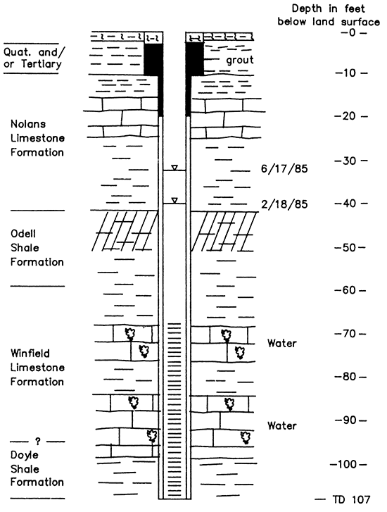
An additional problem for well L19 is the presence of the Herington Limestone Member at 15 to 24 ft as indicated in the driller's log. Even if the well was effectively grouted to a depth of 20 ft, the basal four feet of the Herington is still exposed in the annular space of the well providing a potential hydraulic interconnection between the Herington and Winfield aquifers. Figure 14 illustrates the well construction details with respect to the geology at well L19.
In addition to the aforementioned regulations, wells had to be completed with at least one foot of casing above ground and topped with a sanitary well seal and a well vent. These restrictions essentially prohibited completing water wells in pits or underground and were dutifully adhered to by the water-well contractors to a point. Since most contractors did not install the pump or the connections from the well to the point of use, they did not always have control over the final phases of well completion.
Pump-installers, however, were involved with the final construction phases. Working with the well owner, they determined the type of pump used, where it was to be located Cif not a submersible pump), whether or not a pitless adaptor or unit was used (also if installed correctly), and whether or not a sanitary well seal and well vent were installed properly. Most of the newer wells constructed and completed in the study area did not have an approved well vent installed. However, one of the functions of the well vent was remedied, in most cases, by the types of sanitary well seals utilized which allowed the well to 'breath' without allowing contaminant entry. A few cases of water-well contamination due to improper well venting are discussed in the literature (Joyce, 1982; van der Kamp and Owusu, 1984; Keech, 1984).
Abandoned Wells
Whether constructed and abandoned before or after the establishment of water-well regulations, abandoned wells that are not plugged or have not been properly plugged have the potential for affecting ground-water quality and quantity. In addition to water wells, other abandoned and unplugged or improperly plugged wells (oil and gas), test holes, and seismic-shot holes, etc., have the potenial for affecting ground-water quality.
Historically, the plugging of abandoned water wells has never been a high priority issue in Kansas owing to the fact that the responsibility rests on the land owner (K.A.R. 28-30-7) [see Appendix IV], who many times lacks an understanding of the nature of ground water and the effect that a hole in the ground, such as an abandoned well, can have on ground water.
There are abandoned and unplugged and some improperly plugged wells in the study area. Many have been identified, others reported, and undoubtedly others unknown by anyone to exist.
In a conversation with Mr. Riffel, he reported that he had been hired by the local plumber/pump installer to plug many old wells in Lincolnville. Since most of the wells to be plugged had galvanized steel casing, Riffel pulled the casing (where possible) and/or drilled down 10 to 15 ft, and then put a plug "on" the well. As Mr. Riffel put it, there were many old wells that were just "covered up."
Drive-Through Water Well Survey
A 'drive through' Lincolnville was conducted in an attempt to survey the number of wells and the types of completion used. The results are presented in Table 1, in addition to information obtained during the initial water-well inventory and by word-of-mouth. The number of wells constructed after 1974, most of which met minimum construction standards, was based on the number of WWC-5 forms on file at the Kansas Geological Survey. Three wells located outside of town but in the study area were included.
In summary, some of the methods of water-well construction and completion used in Lincolnville, Kansas, can result in potential hydraulic interconnection between the Winfield aquifer and shallower, seasonally-water-bearing zones in the Herington Limestone and/or soil mantle.
Table 1--Well Completion Survey
| Number of wells | Percent of total | |
|---|---|---|
| Post-1974 wells | ||
| Ks. Dept. Health & Environ. Standards | 20 | 17 |
| Pre-1974 wells | ||
| Above ground in well house | 39 | 33 |
| Below ground in well pit | 22 | 19 |
| Underground completion | 3 | 2 |
| Basement completion | 4 | 3 |
| Inside completion in garage | 1 | 1 |
| Abandoned, not plugged | 16 | 14 |
| Unknown completion | 13 | 11 |
| Total | 118 | 100 |
Prev Page--Introduction and Study Area || Next Page--Results
Kansas Geological Survey, Geohydrology
Placed on web March 16, 2016; originally published 1998.
Comments to webadmin@kgs.ku.edu
The URL for this page is http://www.kgs.ku.edu/Hydro/Publications/1988/OFR88_26/03_back.html