![]()
Prev Page—Recharge and Discharge || Next Page—Utilization of Water
Ground Water, continued
Recovery
Springs
In Scott County, some water is recovered from springs for domestic and stock use and, in at least one case, for public supply, but the supplies thus obtained, with the exception of several of the larger springs in Scott County State Park, are generally small. Small springs are found in the northern part of the county along the valley sides of Beaver Creek and its principal tributaries and along northward-flowing tributaries of Chalk and Hell creeks. The locations of several of the more important springs are shown on Plate 2.
Most of the springs observed in this area are gravity springs; the water does not issue under artesian pressure, but is at the outcrop of the water table. Seepage areas were also observed along the valley sides of these streams. The water in this type of spring or seepage area percolates from permeable material or flows from openings in the rock, under the action of gravity, as a surface stream flows down its channel. Gravity springs may be further classified as seepage springs, in which the water percolates from numerous small openings in permeable material; as contact springs, in which water flows to the surface from permeable material over the outcrops of less permeable or impermeable material that retards or prevents the downward percolation of the ground water and thus deflects it to the surface; and as depression springs, in which water flows to the surface from permeable material simply because the surface extends down to the water table (Meinzer, 1923a, pp. 50-55). The distinctions between these types of springs are somewhat arbitrary and all may grade into one another.
Most of the springs in Scott County are either contact springs or seepage springs and issue from permeable beds at or near the base of the Ogallala formation near its contact with the underlying Niobrara formation. Water is discharged from many springs of this type on both sides of Beaver Creek and its principal tributaries in Scott County State Park. At some of the seeps there is no visible discharge of water, but the vegetation near the contact is much greener and more luxuriant, indicating that the plants are transpiring ground water as fast as it is being discharged. Although some of these seepage areas are rather extensive, they have not been shown as springs on Plate 2.
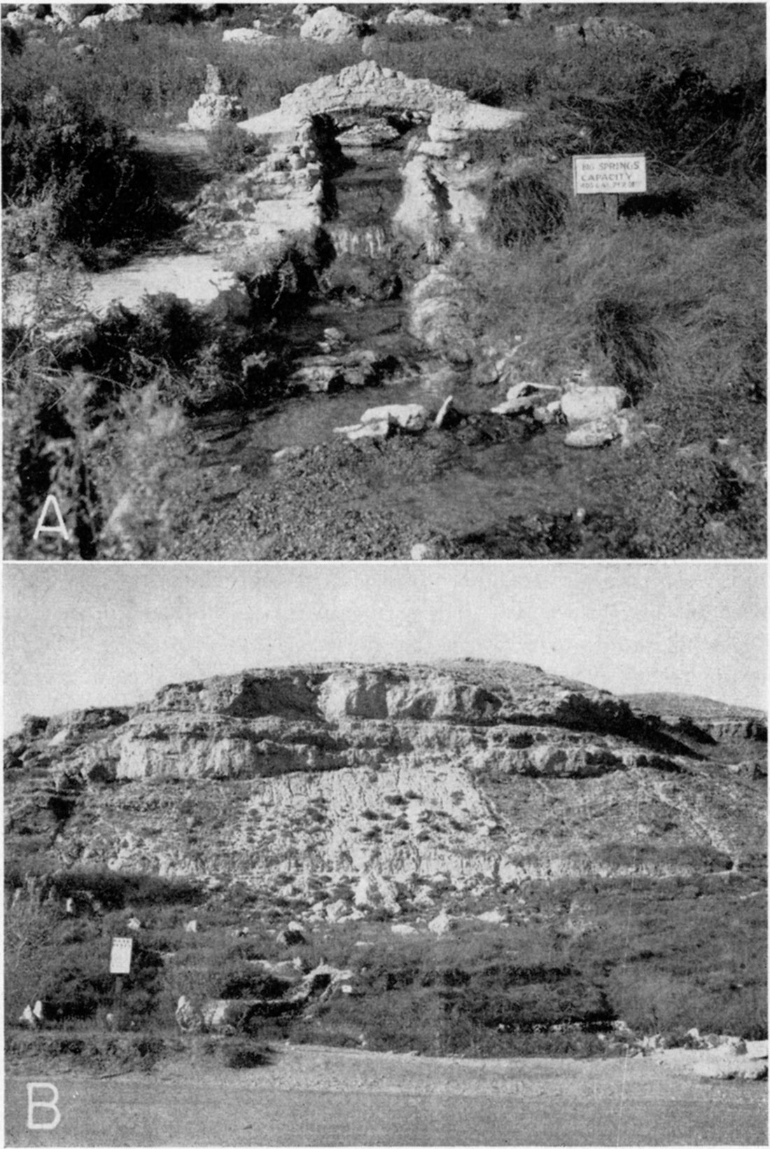
Some of the springs in Scott County State Park have been developed for public use. The best known of this group of springs are the "Old Steele Home" in the park, "Big Springs," and "Barrel Springs" (numbers 16, 17, and 18, respectively). The largest spring observed in the county was "Big Springs" (Pl. 10). This spring has a reported yield of 400 gallons a minute. The yields of other springs in the county are somewhat less and range from a few gallons a minute up to possibly 100 gallons a minute and greater.
Plate 10—A, Closeup view of Big Springs located in Scott County State Park. B, Distant view of above, showing characteristic exposure of Ogallala formation in bluff in background. Springs issue from base of Ogallala formation near its contact with the underlying Smoky Hill chalk member of the Niobrara formation.
Wells
Principles of Recovery from Wells
When a well is pumped there is a difference in head between the water inside the well and the water in the material outside the well. The water table in the vicinity of a pumped well declines and assumes a form comparable to an inverted cone, the apex of which is at the well. When a well is discharged under artesian conditions, there is a comparable lowering of the "piezometric surface" the imaginary surface to which artesian water will rise under its full head. Under artesian conditions the cone of depression exists only as an imaginary cone whose apex is the point of discharge of the well. In any given well the greater the pumping rate the greater will be the drawdown and the greater will be the extent of the cone of depression. Thus the effects of the discharge will be felt at greater distances from the pumped well, and, if heavy pumping continues, the water levels in wells several hundred feet or even a mile or more distant may be lowered somewhat.
The specific capacity of a well is its rate of yield per unit of drawdown and is usually stated in gallons a minute per foot of drawdown. For example, well 91 has a measured yield of 666 gallons a minute with a drawdown of 24.8 feet. Its specific capacity, therefore, is about 26.8 gallons a minute per foot of drawdown. When a well is pumped, the water level drops rapidly at first and then more slowly until conditions of approximate equilibrium are approached, and, in some wells, the water level may continue to decline for several hours or days before approximate equilibrium is established. Drawdown and recovery curves for wells 91 and 137 are shown in Figure 6. In determining the specific capacity of a well, therefore, it is important to continue pumping until the water level remains approximately stationary. When pumping stops, the water level rises rapidly at first, but the rate of recovery becomes progressively slower and may continue long after pumping has ceased.
The cost of pumping water can be reduced by increasing the specific capacity of a well, because the cost of pumping increases with the drawdown. The specific capacity of wells sometimes can be increased by modern methods of well construction, some of which are described under "Drilled Wells."
Methods of Lift
Most of the rural residents in Scott County derive their domestic and stock supplies from wells equipped with lift or force pumps, which are operated by windmills, engines, electric motors, or in some cases by hand. Some of the farms have been equipped with small pneumatic pressure systems in which the water is forced against air pressure into an air-tight tank from which it flows under pressure to any part of the home or farm.
All irrigation wells in Scott County are equipped with deep-well turbine pumps. A series of connected turbines or bowls are submerged below the water table (or just above in some wells) and are connected by a vertical shaft to a pulley or vertical motor at the top, or to internal combustion engines through geared heads. The number of such units varies, depending on the height the water must be forced, but the average installation in irrigation wells in Scott County comprises three stages. Approximately 45 percent of the irrigation wells in Scott County are powered by electric motors, about 31 percent are powered by natural-gas engines, approximately 13 percent are powered by gasoline engines, and a few are operated by diesel engines and tractors.
Practically all industrial wells in the area, including the railroad and municipal wells in Scott County, are equipped with deep-well turbine-type pumps driven by electric motors.
Dug Wells
Of 280 wells in Scott County visited in 1940, seven were dug wells. Of these seven dug wells, two supplied water for domestic and stock use and five were out of use. Most dug wells tap rather poor water-bearing material, but because of their large diameter they have a large infiltration area and ample storage capacity. Dug wells generally are curbed with native rock, but four of the dug wells in Scott County are left uncased and one well has been curbed with old steel boilers. Practically all the dug wells are approximately 4 feet in diameter and the total depths of the wells range from about 20 to 85 feet.
Drilled Wells
Several methods of drilling wells have been employed in Scott County. Most of the domestic and stock wells in the county have been drilled by cable-tool rigs. The cable-tool method is also known as the percussion method and is sometimes referred to as the churn-drill method. Several other special methods for drilling irrigation wells in the county have been developed by local drillers. One of these methods makes use of a large-diameter auger-type bucket (Pl. 9A) that is used in conjunction with an orange-peel bucket (Pl. 11A). In this method blind or dummy casing (Pl. 12B), 42 to 46 inches in diameter, is used in constructing gravel-packed wells. The hydraulic-rotary method as well as the jetting method have been employed in connection with the drilling of small-diameter test holes for irrigation supplies. In 1940, hydraulic-rotary methods were also used for constructing irrigation wells, and several wells have been put down by this method since that time. A portable hydraulic-rotary drilling rig was used for this purpose (Pl. 11B). Another method that has been very successful in the construction of large wells is an adaptation of the California mud-scow method with some modification. In this method a heavy bailer with a cutting shoe and a reaming attachment is used (Pl. 13B).
Plate 9A—Auger-type bucket used in drilling irrigation wells. Bipod set up over site of well 139.
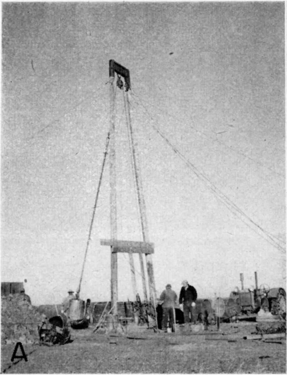
Plate 11—A, Orange-peel bucket in open position ready to be lowered into hole during construction of well 114. B, Rotary hydraulic drilling rig used in putting down irrigation wells.
A standard cable-tool rig consists essentially of a mast, two-line hoist (cable drum), one for the tools and the other to operate the bailer or sand bucket, a walking beam (spudder) for raising and dropping the tools, and an engine for power. The unit is generally mounted on a truck or trailer. The mast is made so that it can be folded down over the machine for moving. Drilling is accomplished by the breaking up of the rock by the impact of a heavy bit that is lifted and dropped at regular intervals. The crushed material is removed from the hole by means of a bailer or sand bucket. In the hydraulic rotary method, the equipment necessary consists of drill pipe, drill bits, mud pump, derrick or mast hoist with drill line for handling pipe, power unit, rotary table, swivel, and hose. This equipment is generally mounted on a truck or trailer unit. The rotary table is at the rear, and the mast is in a vertical position above the rotary table when drilling and folds down over the truck when moving. Mud is pumped from a pit by the mud pump to the drill pipe under pressure and out through the openings in the drill bit. The pipe is rotated continuously while drilling. The drill pipe is rotated by the rotary table either by use of a Kelly or clamps that fasten to the drill pipe. In this method, removal of the cuttings is accomplished by circulating mud-laden fluid down through the drill pipe and up through the annular space between the drill pipe and the hole. The cuttings are brought to the surface as fragments suspended in the mud and are allowed to settle out into a sump or pit. The mud fluid is then picked up by the mud pump and recirculated. The mud also serves to plaster the walls of the hole and to prevent the formations from caving until the casing is installed.
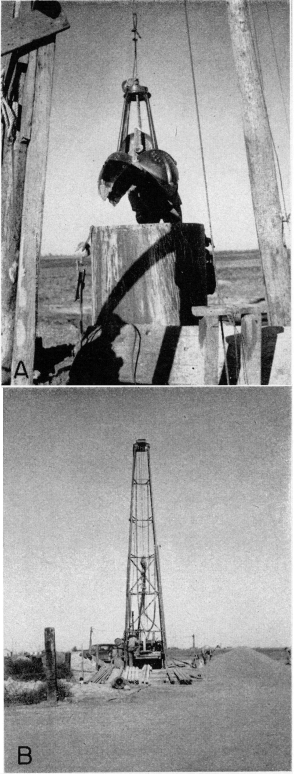
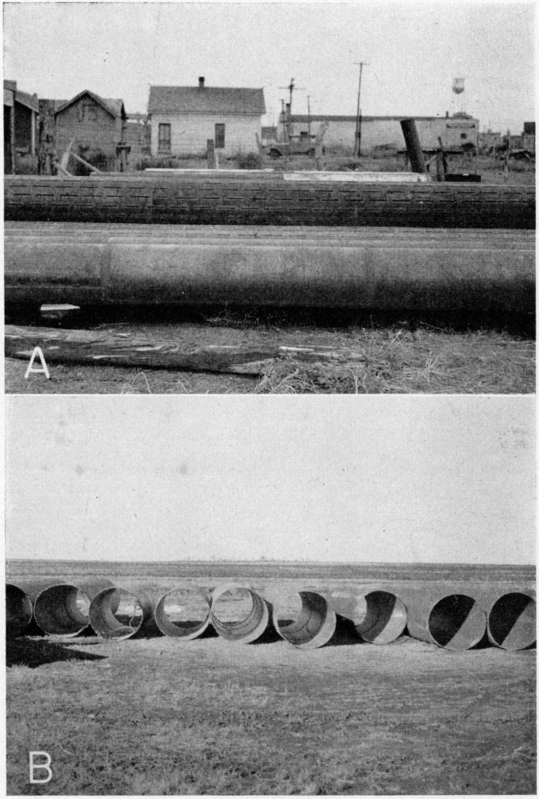
Plate 12—A, View of 18-inch boiler-steel casing used for irrigation wells. Sections of blank casing in foreground; torch-perforated screen casing in background. B, End view of 42-inch blind or dummy casing used in constructing gravel-packed irrigation wells.
The equipment used in the jetting method consists of a string of pipe, a jetting bit, a pressure pump for forcing water through the bit, and a hoisting mechanism for handling pipe. Drilling is done by means of water forced through the drill bit under pressure. The bit is turned slowly by hand or where hard formations are encountered, the drill stem with bit attached to lower end is raised and dropped by use of spudding equipment, this action pulverizing the formation being drilled so that the water that is forced through the bit under pressure will carry the drill cuttings to the surface. An adaptation of this method has been used by local drillers in the county for test-drilling purposes only. Small portable drilling machines have been built by the drillers for this purpose.
Construction of wells in consolidated rocks—A few drilled wells in the southeastern quarter of Scott County obtain water from consolidated rocks--shale and limestone. In most of these wells the water enters only in the lower end of the casing; these are called open-end wells. In some wells, however, the casing extends to the bottom of the hole and the water enters the well through a section of screen or slotted casing placed opposite the water-bearing material. This type of well is generally cased only a short distance into the rock, the lower part of the hole being left uncased. The yields of drilled wells in the several consolidated deposits in Scott County are discussed on pages 114 and 118; the records of all wells visited are given in Table 19.
Construction of wells in unconsolidated deposits—Most of the drilled wells in Scott County obtain water from unconsolidated material (sand or gravel). The principal unconsolidated water-bearing deposits are the Tertiary Ogallala formation and the undifferentiated Pleistocene sands and gravels. Wells in these deposits generally are cased nearly to the bottom of the hole with galvanized-iron or wrought-iron casing. In some wells the water enters only at the lower open end of the casing, but in many wells—particularly those used for irrigation—the casing is perforated below the water table to provide greater intake facilities.
The principal type of domestic and livestock well in Scott County is a cased drilled well containing a separate pipe and cylinder for conducting the water to the surface. The wells are generally from 4 to 6 inches in diameter. Many of the larger municipal and industrial wells and practically all the irrigation wells that have been drilled in the county in the last several years are gravel-packed. In places where the water-bearing materials are fine-grained, the gravel-packed wells have several advantages that offset the greater initial cost. The envelope of selected gravel that surrounds the screen increases considerably the effective diameter of the well, thereby decreasing the velocity of the water entering the well. This reduction in velocity prevents the movement of fine sand into the well and increases the production of sand-free water. Owing to the increased effective area offered by this type of construction, the entrance friction of the water is reduced and the drawdown may be reduced materially. As stated above, a reduction in drawdown at a given yield means an increased specific capacity and reduces the cost of pumping.
Assuming that a well of the best possible construction is employed, then the maximum amount of water that can be withdrawn from the well is fixed by nature and nothing more can be done to make the well yield more than the water-bearing material will provide. The problem for the driller, then, is to construct each individual well in such a manner as to obtain the greatest yield with the smallest amount of drawdown that is possible under the existing conditions. For further discussion of gravel-packed wells the reader is referred to a report by Rohwer (1940, p. 62). Some of the factors that influence the cost of pumping water have been summarized by McCall and Davison (1939, p. 29):
"First, the well should be put down through all valuable water-bearing material. Second, the casing used should be properly perforated so as to admit water to the well as rapidly as the surrounding gravel will yield the water. Third, the well should be completely developed so that the water will flow freely into the well. ... Increasing the diameter of the well will decrease the drawdown but little, all else remaining equal. The small saving in lift due to use of a large casing usually will not offset the extra cost of the larger well. It is much better to put a 16-inch casing down through all valuable water-bearing material than to start a 24-inch casing and have to stop short of the desired depth. Increasing the depth of the well will have a greater effect on reducing the drawdown than will increasing the diameter, so long as additional water-bearing formations are encountered."
For a description of different types of pumping plants, the conditions for which each is best adapted, construction methods, and a discussion of construction costs, the reader is referred to a report by Davison (1939).
In constructing a gravel-packed well a common practice is to use an auger-type bucket to drill down through the materials underlying the surface until the walls of the open hole will no longer stand. This type of equipment can sometimes be used effectively to depths as great as 70 feet. In one instance an auger-type bucket, 24 inches in diameter and 30 inches long, has been used (Pl. 9A). The bucket is equipped with a reamer at the top that will cut up to a 50-inch hole and the 24-inch bucket at the bottom acts as a pilot. The bucket is rotated by means of a square Kelly rod that operates through a rotary table at the surface. An orange-peel bucket is very effectively used in conjunction with the auger-type bucket for removing sand and soft clays from the hole (Pl. 11A). Blind or dummy casing from 42 to 46 inches in diameter is placed in the hole as drilling progresses. The usual practice is to drill slightly ahead of the dummy casing, and as the hole increases in depth, the dummy casing is lowered correspondingly. After reaching the total depth the well screen or perforated casing, generally from 16 to 24 inches in diameter, is then lowered into the hole and graded gravel is placed in the annular space between the permanent well screen and the blank or outside casing. The outer casing is then withdrawn to uncover the screen and allow the water to flow through the packing from the water-bearing material. One driller uses a method for constructing large-diameter wells that is an adaptation of the California mud-scow process. Pre-perforated steel casing is used entirely and locations that have been previously investigated through test drilling are drilled. Vertical slots are cut in the casing using a torch and the sections are torch-welded (Pl. 12A). In this method, a 30-inch open hole is first drilled down to the water-bearing strata. Steel casing, 16 inches in diameter, with a 26-inch bell on the bottom, is then placed in the hole. The larger-diameter bell on the bottom serves as a cutting shoe. As drilling progresses the hole is bailed clean until it is free from all mud, and the annular space between the casing and the open hole is then back-filled with graded gravel. An ordinary bailer, 15 inches in diameter and 18 feet in length weighing approximately 1,200 pounds is operated inside the casing for removing the materials from the hole. Another type of bailer is also commonly used in this method and is equipped with a reaming attachment 26 inches in diameter that acts as a cutting shoe. This type of bailer is 17 inches in diameter and 17 feet long and weighs more than 2,000 pounds (Pl. 13B). In constructing irrigation wells with this type of equipment, cable-tool methods are used entirely. A set of jaws that weigh approximately 1,000 pounds are also used with this equipment.
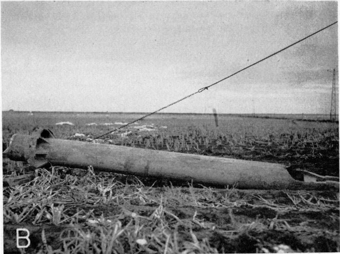
Plate 13B—Bailer with cutting shoe and a reaming attachment used in constructing large wells by a modified California mud-scow process. Bailer is 18 feet long and 17 inches in diameter; weight approximately 2,000 pounds.
There are several advantages in using this method of constructing wells. When the large bailer is operated inside the well casing, a surging effect is established with the result that fine sand moves inside the casing through the perforations and can be removed with the bailer. The well can then be developed by back-filling with graded gravel. The gravel replaces the fine sand that is drawn into the well by the surging process. After the well is completed, the surging is continued by operating the large bailer in connection with the drilling motion throughout the length of the perforated portion of the screen. This process is continued until fine sand ceases to come into the well, and gravel is added at the surface as needed. A solid drilling stem is not used in this method-the heavy bailer with the reamer attachment acting essentially as a drilling tool. A standard rig weighing approximately 7 tons and mounted on a trailer has been used for this type of equipment.
Nearly all the drillers have designed small test-drilling rigs for the purpose of putting down small-diameter test holes. Most of the smaller rigs are homemade and are equipped with small rotary mud pumps powered by small gasoline engines. Ordinarily the drill pipe is rotated by wrenches that are operated by hand. One such test rig used 1 1/4-inch pipe with a drill bit on the end, which drills a 3-inch hole. Another outfit is equipped with 1-inch pipe for drill stem.
Test-drilling prices in 1940 ranged from about 10 to 15 cents per foot for drilling in clay and sand. If hard-cemented strata were encountered, the drilling costs ranged from 25 to 35 cents per foot. One driller charged 50 cents per foot for test drilling, but if the test hole was used eventually as a pilot hole for the permanent well, no charges were made for the test drilling.
In 1940, several irrigation wells were also put down with a portable hydraulic-rotary drilling rig (Pl. 11B). In this method a hole is first drilled using a 10-inch fishtail bit mounted on the end of 4-inch drilling pipe. This type of bit is usually used for soft formations and when hard-cemented beds are encountered, a three-cone, rock bit (Hughes rock bit) 10 inches in diameter is used. After the 10-inch pilot hole has been completed to the total depth, the 10-inch bit is removed and a 28-inch three-blade reaming bit with a 10-inch pilot below is attached to the end of the drill pipe. The 10-inch hole is then enlarged to a 28-inch hole by hydraulic rotary methods, the sides of the hole being mudded up with the drilling mud that is used in connection with this method. Casing ranging in diameter from about 16 to 20 inches is then lowered into the hole until the bottom end is about 3 inches off bottom. The casing is suspended on guides in the hole. The drill pipe is then lowered into the bottom of the hole and circulation is again started to wash away the mud from the inside and outside the casing. Screened gravel is introduced slowly from the surface into the annular space between the casing and the side of the hole as this washing process continues. The washing process helps remove much of the mud fluid from the sides of the hole. When the top of the perforated screen is reached with the gravel pack, the wash pipe is removed and is then put down on the outside of the casing and the annular space between the casing and the hole is back-filled with gravel to the land surface. The mud is then bailed out of the hole down to water level to allow free entry of the water into the well. As soon as the gravel pack is completed to the surface, clear water is introduced throughout the gravel pack before the mud becomes fixed. A bailer 10 inches in diameter and 20 feet in length with a dart valve on the bottom and having a capacity of 65 gallons is lowered into the hole and the well is then bailed for an extensive period. Following this, a belting swab is lowered into the hole for the purpose of surging the well. Clear water is introduced through the gravel pack during all of these operations. Swabbing operations are alternated with bailing operations.
The hydraulic rotary rig that was used in Scott County was mounted on a truck chassis, and the derrick was constructed of tubular steel and was 40 feet high in drilling position. The 4-inch standard oil-well drill pipe was operated by a 4-inch square Kelly that passed through a rotary table mounted at the rear of the drilling rig. A 4-inch core barrel 20 feet long equipped with three 8-inch wash pipes running the length of the barrel on the outside was used for obtaining core samples of any promising gravel.
Prev Page—Recharge and Discharge || Next Page—Utilization of Water
Kansas Geological Survey, Geology
Comments to webadmin@kgs.ku.edu
Web version March 2003. Original publication date July 1947.
URL=http://www.kgs.ku.edu/General/Geology/Scott/05_gw4.html