Prev Page--History || Next Page--Summary, Appendix, References
Environment
Water
Introduction
The 60-year-old Gorham oil field has affected its environment adversely by leaving a heritage of brine pollution of some freshwater aquifers, an interstate highway subsiding slowly in three areas, and 50 mi2 (130 km2) of agricultural lands somewhat impaired. These aspects are summarized briefly. Walters (1959, p. 60-75) has previously discussed the history of brine disposal, oil-well plugging or non-plugging, and highway subsidence in the Gorham oil field.
Freshwater aquifers
In the oil-field areas of Russell County, including the Gorham, Russell, and Hall-Gurney oil fields, two shallow freshwater aquifers became contaminated in some local areas with oil-field brines in the 1930's. Prior to contamination, the first aquifer, the near-surface alluvium present in creek and river valleys, yielded limited amounts of excellent-quality freshwater. For example, Frye and Brazil (1943) state that Victoria, 6 mi (9.6 km) west of the townsite of Gorham, derived its municipal water supply from four dug wells 35 ft (10.5 m) deep in secs. 2 and 12, T. 14 S., R. 17 W., and in sec. 18, T. 14 S., R. 16 W. A composite water sample from the four wells that yield water from the Pleistocene sand contained only 14 parts per million (ppm) chloride and 445 ppm total-dissolved solids (TDS). Almost all the water analyses available in the literature are expressed in the old terminology of parts per million (ppm) as here quoted. When more modern analyses, expressed in milligrams per liter (mg/L) are available, they are so quoted.
A second aquifer is the Dakota Sandstone which contained potable water in limited areas. Frye and Brazil (1943) give the following information: two municipal water wells for the city of Bunker Hill, 24 mi (38 km) east of the Gorham townsite and outside of the oil-field area, yielded water from a depth of 250 ft (75 m) with a chloride concentration of 440 ppm and TDS content of 1,270 ppm. These Dakota sandstone wells are in sec. 6, T. 14 S., R. 12 W. A nearby Dakota well in sec. 12, T. 14 S., R. 13 W., with a total depth of 244.6 ft (73 m), yielded water with only 85 ppm chloride and only 672 ppm TDS. Another Dakota sandstone well nearby in sec. 10, T. 14 S., R. 12 W., depth 183.9 ft (55 m), yielded water with 23 ppm chloride and 466 ppm TDS. In contrast, four Dakota water wells within the Gorham oil field tested by Frye and Brazil in the summer of 1941, averaged 7,655 ppm chlorides and 16,652 ppm TDS. These figures may represent extreme conditions. In the Bunker Hill area, the Dakota formation is shallow and close to the outcrop. It is influenced by percolating rainfall and represents the best of conditions for freshwater in the Dakota sandstones. The most characteristic feature of the Dakota formation is its variability. Sandstones are lenticular, discontinuous, and are inferred to have been deposited mainly by streams and rivers (Bayne et al., 1971). The sandstone lenses act as separate aquifers and are thought to have contained waters of varying salinity prior to oil activity in the area. All studies of the quality of the water in the upper and lower Dakota aquifers are handicapped by the lack of base-line data on the water quality prior to the discovery of the Gorham oil field. Even the early investigators, Frye and Brazil (1943), working in 1941 when the oil field was 15 years old, could not ascertain the pre-oil-field water quality, but could only show that the average analysis of the Dakota water from within the limits of the oil field was notably higher in chlorides and TDS than contemporary analyses of Dakota water from outside the oil-field areas.
The town of Gorham had no municipal water supply in the late 1930's and the early 1940's. In those years, too, the municipal water supply for the city of Russell was changed from water wells to surface water from the Smoky Hill River and Big Creek. The surface water was of poor quality as compared with the prior water supply. Latta (1948) states that" At some periods during the last several years when the stream (Smoky Hill River) was at low stage, the chloride content of the intake has been as high as several thousand parts per million for short periods; and for periods of many days, water in the city mains has averaged 1,100 ppm chlorides. The supply from Big Creek, although of better quality, is not adequate to treat the total needs of the city."
The saline contamination of two freshwater aquifers in local areas was part of the environmental price paid for Russell County oil fields. How did the alluvial and Dakota Sandstone aquifers become contaminated with oil-field brine in some local areas?
Disposal of oil-field brine, 1926-28
For the first two years after the discovery of the Gorham oil field in 1926, the disposal of saltwater was not a problem. All the early wells produced from the Lansing-Kansas City limestones, then termed "Oswald" by correlation with the famous 1923 discovery of the Fairport oil field on land owned by the Oswald family. The Lansing-Kansas City reservoirs are characterized by solution-gas drive. The wells produced but little saltwater along with the oil.
Disposal in surface ponds, 1928-1930's
The discovery on January 28,1928, of oil in the Gorham sandstone changed the situation. Saltwater production was not yet a problem three months later on April 14, 1928, when the cover photograph was taken but became one soon after. The historical map (fig. 30) shows the intense activity on April 14, 1928, following the discovery of this major prolific oil reservoir with a strong water drive. For a few weeks the Gorham area was a "hot spot" and was perhaps the most exciting place in the U.S. oil business.
The new Gorham sand oil wells, produced at capacity, were soon making large volumes of saltwater along with the oil. For example, the Day #3 in the NE SE NE sec. 32, T. 13 S., R. 15 W., produced 60 BOPD and 50 BWPD initially when completed January 30, 1930.
During the late 1920's and early 1930's, there were no regulations and it was accepted practice to store brine produced with the oil in surface ponds. Ultimately the water may have evaporated but the salt did not. Brine seeped into the soil and eventually made its way into the shallow freshwater aquifers, or else brine washed into the surface stream drainage during storms which eroded out the earthen embankments. Ponds continued to be used into the early 1950's, by which time many of the Reagan Sandstone oil wells were producing 90% saltwater in amounts exceeding 100 barrels of water per day per well. Such ponds are abundantly visible on 1938 and 1951 photographs studied.
Photographs of saltwater ponds in the oil fields of central Kansas were published by Jones (1945, 1950) who discussed the fallacy of considering them "evaporation ponds." Any evaporation of water from brine ponds did not decrease the potential contamination because the residual salts could be redissolved by water from later atmospheric precipitation. Jones (1950) advocated the use of deep disposal-wells in the Arbuckle formation in place of the brine storage ponds and the shallow SWD wells then in common use with depths from 400 to 800 ft (120-240 m).
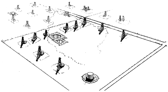
Fig. 38 is the first of a series of pen and ink drawings by artist Steve Van Buskirk from the vertical air photographs studied. The drawings are drawn from the poor-quality, old photographs supplemented by production records and well-plugging reports. Note that one large pond for storage of produced brine was not sufficient so that a second smaller pond was constructed. These ponds were constructed as evaporation ponds and not as dams in valleys or waterways. At times, the ponds became completely filled, shutting down oil production until additional pond storage was available. A heavy summer storm occasionally over-filled such a pond causing run-off and rapid erosion of the pit wall, dumping the entire brine content into the swollen waterways. Such an "act of God" was welcomed because the pond retaining wall was easily repaired, permitting oil production to be resumed. Virgil B. Cole (personal communication, 1976) stated that old timers in the area suggested that sometimes God was assisted in his "act" by clandestine midnight hand-shoveling of a gap in the pond wall while the storm raged. At any rate, not only were the ponds inadequate to hold the large amounts of oil-field brine, but by the late 1930's, it was recognized that these extensive "evaporation" ponds leaked brine downward, infiltrating and polluting the near-surface alluvial aquifers.
Figure 38--Roubach lease, the NW sec. 2, T. 14 S., R. 15 W., in 1938. View toward the southwest. The 10 oil wells were drilled with cable tools. The derricks were left in place for production use. Oil is produced into the 55,OOO-barrel storage tank (foreground). Brine produced with the oil is disposed in the two "evaporation ponds." Sketch by artist Steve Van Buskirk from poor-quality vertical aerial photographs supplemented by production records and well-plugging reports. Sketch is repeated as part of a larger area in fig. 47, p. 82.
A sad personal story concerning oil-field ponds and the pollution of the Dakota aquifer was related to me by Clarence Keil (personal communication, 1983). It is a representative story for the events of those years. Clarence Keil grew up on a family farm 6 mi (10 km) south of Russell in the Hall-Gurney oil field near the Smoky Hill River. He told me about the big clear cool spring on their family farm, SE sec. 36, T. 14 S., R. 14 W. The spring came out of the Dakota Sandstone on the hillside. As a boy in the 1940's, he remembers going often with his father to take cans of cream to the Dole Creamery in the city of Russell where the water supply had become salty. His father took a dozen gallon jugs of spring water each week for the Dole family who operated the creamery. They were the parents of U.S. Senator Bob Dole. On Sunday afternoons, Keil recounts, as many as 20 automobiles were parked on the road at their farm while the visitors from Russell waited in line to fill water jugs. Later the spring became too salty to drink and the big cottonwood trees surrounding it died. One "evaporation pond" for storage of waste oil-field brine was in use 0.25 mi (0.4 km) west of the spring on the Keil land, another was on the neighbor's land at a higher elevation 0.5 mi (0.8 km) north in the NE sec. 36, and two brine ponds were in use on the NW sec. 36. Officials of a major oil company operating the four oil wells on the Keilland assured the family that their oil wells and others in the Hall-Gurney oil field had nothing to do with the changes in quality of the spring water.
Disposal in shallow SWD wells, 1940's
Beginning in the 1930's, permits were issued for the use of shallow saltwater-disposal wells, defined as wells disposing brine in aquifers (salifers) at depths more shallow than the salt that was encountered from 1,200 to 1,500 ft (360-450 m). Saline contamination of shallow freshwater aquifers by oilfield brines became a problem by 1941. The Kansas Geological Survey conducted a study that year of oil-field brine disposed in the Gorham oil field, and in adjacent parts of Russell and Ellis counties. Test holes were drilled and water samples collected. This study (Frye and Brazil, 1943) was interrupted by World War II before completion, but official approval was given by the Kansas Corporation Commission for disposal of oil-field brines in shallow brine-bearing aquifers, the Cheyenne Sandstone and the Cedar Hills Sandstone, at depths near 400 to 800 ft (120-240 m). Frye and Brazil mapped 22 such shallow SWD wells within the present Gorham oil field of which four affected the Witt and Crawford sinks. Operations were not always discriminating as to the shallow sandstones used, and it was prior to this study that the chloride count in the Dakota aquifer reached 7,655 ppm average of four locations, as compared with 303 ppm chlorides in the non-oilfield areas.
Fig. 39, Roubach lease in 1951, shows the evaporation ponds still holding brine. A shallow SWD well (not visible on the 1951 photograph) near the tank battery was disposing oil-field brine into the Cheyenne Sandstone from 459 ft to 482 ft (138-145 m). There are six remaining oil wells. On the adjacent Crawford lease, left distance, only two of the nine wells shown in 1938 remain. Abandoned are twin wells, Crawford No. 12 and No. 16, at the site of the future Crawford sink affecting I-70. The Crawford lease, too, disposed oil-field brine in a shallow saltwater-disposal well in the Cheyenne Sandstone as did the Witt and Foster B leases comprising the E/2 sec. 3 to the west (right) in fig. 39. Shallow SWD wells for which records survive in the W/2 sec. 2 and the E/2 sec. 3, T. 14 S., R. 15 W. are shown in table 6.
Figure 39--Roubach lease, 1951. The two saltwater "evaporation ponds" are full. Brine pumped from the six remaining oil wells is disposed in a shallow saltwater-disposal (SWD) well 482 ft (145 m) deep (not shown). Oil is being stored in the battery of tanks. Sketch by Steve Van Buskirk.
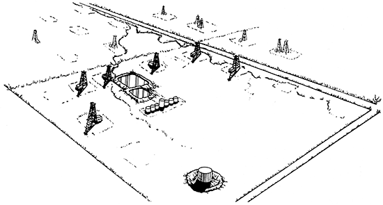
Table 6--Shallow SWD Wells, W/2 sec. 2 and E/2 sec. 3, T. 14 S., R. 15 W.
| Lease | Location | Disposal depth |
Years |
|---|---|---|---|
| NW 2 | |||
| Roubach SWD#1 | 1,055 FEL, 880 FSL, NW | 459-482 | 1938 (still in use in 1986) |
| SW 2 | |||
| Crawford SWD#1 | 1,175 N of SL, 1,284 E of WL, C SE | 443-653 | 9-26-1936, 9-10-1971 |
| NE 3 | |||
| Foster "B" SWD#1 | 1,250 FEL, 1,300 FSL, NE | 515-925 | 8-28-1949, 1-31-1956 |
| SE 3 | |||
| Witt "A" SWD#1 | C S/2 N/2 SE | 520-920 | Nov. 1946, 4-07-1956 |
| V. Witt SWD#1 | SE SW SE | 483-880 | 2-21-1945, 1-31-1956 |
| Witt #8 OWWO SWD | NW SW SE | 750-795 | 7-24-1936, 3-26-1956 |
The disposal formation for depths of 443-500 ft (133-150 m) is the Cretaceous Cheyenne Sandstone; for depths below 500 ft to near 925 ft (150-278 m), it is the Cedar Hills Sandstone. In these SWD wells the white Cheyenne Sandstone directly overlies the red Permian Cedar Hills Sandstone. An early study by Don Butcher (personal communication, January 1990) confirmed that the Cheyenne Sandstone was very friable with only a minor amount of carbonate cement. Acidizing of the formation, along with the surging effect due to releasing pressure when the pump was shut off, caused loose sand to fill the lower part of the bore hole. The Cheyenne disposal wells, therefore, initially took brine by gravity flow but required increasingly higher pressurers with use. Licensing of new Cheyenne SWD wells was discontinued in the 1960's as a result of this study.
Virgil B. Cole (personal communication, 1975), an experienced field geologist, witnessed saltwater springs breaking out on the hillsides in secs. 14 and 23,2 mi (3.2 km) south of the area under discussion, due to excessive input pressures in shallow saltwater-disposal wells and to the large volume of disposed brine. He related that when injection pressures became too high due to plugging of the SWD well with sand, it was common practice to re-drill shallow saltwater-disposal wells a few feet away from the plugged-off hole so that some locations had two or three shallow SWD wells within a few feet of each other.
Many shallow SWD wells were plugged and abandoned in the 1950's when deep Arbuckle SWD systems were installed. In the course of years of operation of shallow SWD wells, the Dakota sands from the depth of 150 to 350 ft (45-105 m) became contaminated with salty oil-field brines in some areas within the Gorham oil field.
Corrosion caused by brine disposal in shallow SWD wells
The shallow SWD wells licensed by the KCC provided a place to put the produced saltwater when the construction of new surface-evaporation ponds was discouraged in the mid-1940's, then prohibited by legislation passed in 1957. The shallow SWD wells had other unplanned results. Albert Abercrombie (personal communication, August 25, 1988, and other times) was employed by Sohio Petroleum Company as foreman in the Fairport-Gorham district from the spring of 1944 to January 31,1948. The principal part of his work was the recompletion of oil wells either to put new zones on production or to repair damage due to corrosion. All of the 18 oil wells on the Foster A lease, the NE and N/2 NW sec. 3, T. 14 S., R. 15 W. were drilled with cable tools as were the eight wells on the Witt lease N/2 of SE sec. 3 and the six wells on the Foster B lease, the S/2 NW sec. 3. In producing wells the only casing left in the holes were short strings of large conductor pipe such as 20 ft (6 m) of 20-inch (50-cm) diameter and oilstrings of 7-inch (17.5-cm) casing (6 5/8 inches [16.5 cm] i.d.) either set in the Kansas City near 3,000 ft (900 m) or set in the Reagan Sandstone near 3,300 ft (990 m). These casing strings were uncemented. This left the annular space outside the 7-inch (17.5-cm) pipe open from the base of the surface pipe to the end of the oil string. Abercrombie even found that the triple wells in the NE NE SE sec. 3 on the Witt lease, adjacent to the Crawford sink, had only oil-string casing, uncemented, with no surface pipe at all left in the hole. In that area, the intermediate strings of casing that shut off water during drilling with cable tools were all pulled out of the hole and reused elsewhere. The casing program of the Tony Witt #4-A, drilled 50 ft (15 m) south of the #4 in the NE NE SW sec. 4, T. 14 S., R. 15 W. near the Witt sink, is typical of the casing program for the oil wells:
| Size (inches) |
Depth (ft) |
Pulled Out (ft) |
Left in Hole (ft) |
|---|---|---|---|
| 20 | 20 | 0 | 20 |
| 15-1/2 | 389 | 389 | 0 |
| 12 | 612 | 612 | 0 |
| 10 | 922 | 922 | 0 |
| 8 | 2,765 | 2,765 | 0 |
| 6-5/8 | 3,054 | 0 | 3,054 |
| (and later) | |||
| 5-liner | 3,286 | 0 | 232 |
In the mid 1940's, Abercrombie (personal communication, August 25,1988) completed shallow SWD wells on the Foster A, Foster B, Witt, and other leases. Within two years casing in many of the oil wells corroded opposite the "Dakota," a field term for the Cedar Hills Sandstone, the Cheyenne Sandstone, and the lower Dakota Sandstone. Production from the 8-10-year-old oil wells had declined to a few barrels of oil a day. In some wells the first indication of casing corrosion due to the brines injected into the nearby shallow SWD wells was an increase in oil production from adjacent oil wells. One of the oil wells on the Foster B lease had declined to 3 BOPD from the Lansing-Kansas City formations but after the "Dakota" water broke in on adjacent wells, production increased to over 100 BOPD due to unplanned water-flooding of the Lansing-Kansas City formation. It was Abercrombie's job for many months to "squeeze-cement" well after well through the corroded casing. Procedure was to set a plug near 800 ft (240 m) inside the 7-inch (17.5 cm) casing, then pump cement down the casing, out the corroded holes, into the annular space outside of the 7-inch (17.5-cm) casing and up the hole inside the surface pipe until cement circulated at the surface. If cementing could not be done in this manner, then 1-inch (2.5-cm) pipe was inserted down the annular space and cement injected through it. While cementing the Witt #1 in the NW NW SW sec. 3, T. 14 S., R. 15 W. (the sinkhole well), the 1-inch (2.5-cm) pipe could not be pulled out and was left cemented in the annular space. These personal field experiences of Albert Abercrombie between the spring of 1944 and January 31, 1948, are indicative of conditions in the Gorham oil field during those years. Abercrombie's personal knowledge of field conditions in the portion of the Gorham oil field traversed by I-70 through secs. 2 and 3 provides an understanding of the casing programs, of the uncemented condition of cable-tool holes, and of the corrosive effect of disposing oil-field brines in shallow SWD wells.
Butcher (personal communication, January 1990, while conducting a critical peer review) wrote that in his opinion, "All of the sinkholes in this immediate vicinity were caused by 'Dakota' water moving down uncemented annular spaces in producing wells, dissolving salt." The author agrees with this statement with the additional note that the Topeka fracture zone near 2,700 ft (810 m) was a contributing factor in localizing the sinkholes by providing a vertical communication path (originally for the upward movement of petroleum) for the downward movement of disposed oil-field brines, undersaturated as to salt, by gravity flow. For a summary of the pressure relationships of the various aquifers, see Walters (1978, p. 39-45, 63-68).
Shallow SWD wells; map and years licensed
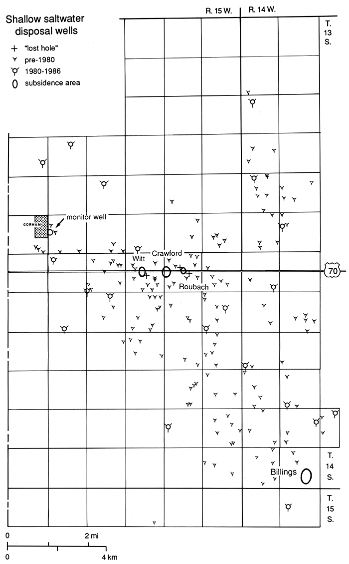
Fig. 40 is a map showing the locations of the 168 shallow SWD wells for which records could be found in the KCC office or elsewhere. None of these shallow SWD wells is shown on other maps of the Gorham oil field in this report. The arrow near the town of Gorham gives the location of the Gorham monitoring site (Macfarlane et al., 1988).
Figure 40--Map showing the location of 168 shallow SWD wells for which records could be found. Also shows Witt, Crawford, Roubach, and Billings subsidence areas. Arrow near town of Gorham indicates KCC 1987 monitor well. Disposal formations were formerly Dakota Sandstone 150-250 ft (45-75 m; early 1940's), Cheyenne Sandstone 440-500 ft (132-150 m; 1930's-1960's) and presently Cedar Hills Sandstone, 500-800 ft (150-240 m; 1930's-1990's). Larger symbols indicate shallow SWD wells licensed 1980-86.
The years in which the shallow SWD wells in the Gorham oil field were licensed by either the KCC or the KDHE, and the number of shallow SWD wells licensed are as follows:
| before 1942 | 22 | Frye and Brazil (1944) |
| 1942-July 1944 | 13 | Swineford (1945) |
| 1944-1949 | 51 | |
| 1950-1959 | 38 | |
| 1960-1969 | 11 | |
| 1970-1979 | 13 | |
| 1980-1986 | 20 | |
| 168 | to January 1, 1987 |
| Formation | Depths | Years Licensed |
|---|---|---|
| Dakota-Kiowa | 250-450 | early 1940's Macfarlane et al. (1988) |
| Cheyenne | 450-500 | 1930's-1960's Butcher (pers. comm., Jan. 1990) |
| Cedar Hills | 500-800 | 1930's-Jan. 1990 KCC and Butcher (pers. comm., 1990) |
Investigation of aquifers affected by shallow SWD wells
The effect of former and present oil-field SWD wells on the Cedar Hills, Cheyenne, and upper Dakota aquifers was investigated by Macfarlane et al. (1988), at the request of the KCC. Monitor sites were established including one at the east edge of the town of Gorham in the NW SW NW sec. 32, T. 13 S., R. 15 W., as part of the hydrogeologic and water-quality investigation. Measurements of three aquifers at the Gorham monitor site on November 23, 1987, provide the following data:
| Aquifer | Depth (ft) |
Static Fluid Level | TDS, mg/L | |
|---|---|---|---|---|
| A* | B** | C*** | ||
| Pleistocene | 0-22 | Not measured | ||
| upper Dakota | 148-245 | 171 | +1,732 | 3,756 |
| lower Dakota | 335-362 | Not measured | ||
| Cheyenne | 460-488 | 197 | +1,706 | 20,640 |
| Cedar Hills | 508-598 | 158 | +1,745 | 19,390 |
| *A, In feet below ground level. Assumed elevation, 1,903 ft. **B, In feet above mean sea level. ***C, Calculated from conductivity measurements. |
||||
Static fluid levels at the Gorham monitor site show that the aquifers are separated by confining beds, but if all aquifers were open in an uncased hole, brine from the Cedar Hills Sandstone would flood the Cheyenne aquifer and also would flood the upper Dakota aquifer that now carries "usable" water. Complete chemical analyses of water samples, presumably taken November 23,1987, were published by Macfarlane et al. (1988). The pressure relationships are influenced by a Cedar Hills SWD well completed in June 1986, only a few hundred feet north of the monitor site and by other Cedar Hills SWD wells to the south.
The aquifers measured at the Gorham monitor site are connected hydraulically within the 100-mi2 (260-km2) study area. In the western part of the study area, the Cedar Hills aquifer is separated by shale from the overlying Cheyenne Sandstone as described at the Gorham monitor site. Throughout the entire mid-part of the study area, the Cedar Hills Sandstone is directly in contact with the Cheyenne Sandstone. An example is the area of I-70 highway subsidence in secs. 2 and 3, T. 14 S., R. 15 W. In the northeast portion of the study area, the Cedar Hills Sandstone is absent by pre-Cretaceous truncation (Frye and Brazil, 1941). Examples are wells 51 and 52, cross section B-C, fig. 6. The Cheyenne Sandstone is hydraulically connected with the overlying lower Dakota aquifer in that area. The saline aquifer system formed by the merging of these three aquifers has a northeastward flow and discharges into the alluvium in the valleys of Salt Creek and the Saline River, the junction of which, in sec. 33, T. 12 S., R. 14 W., is only 2 mi (3.2 km) northeast of well 53 at the northeastern end of cross section B-C, fig. 6. It is noteworthy that both Salt Creek and the Saline River were named by the Indians as translated by the French fur traders (Rydjord, 1972, p. 110) more than a century before the first oil drilling in Russell County. Whittemore and Pollock (1979) as quoted in Macfarlane et al. (1988), identified the saline seepage into Salt Creek as being predominately derived from a halite-brine (natural) source. They state that the saline seepage had, in 1979, a different salinity identification from that found in Cedar Hills and Cheyenne samples at the Gorham monitor site where the waters are similar to those for oil-field brines in the surrounding area. As of 1979, therefore, oil-field brines were not contributing to the salinity of Salt Creek.
Macfarlane et al. (1988) reached the following preliminary conclusions regarding the Gorham oilfield area:
- The Cedar Hills aquifer is hydraulically interconnected with the Great Plains aquifer (Cretaceous; Cheyenne, lower Dakota, and upper Dakota aquifers).
- Saline waters from the Cedar Hills aquifer are moving upward into the Great Plains aquifer.
- Upward movement of saline waters from the Cedar Hills into the Great Plains aquifer may be accelerated by continued use of the Cedar Hills aquifer for disposal of oil-field brines.
Deep-well disposal systems, 1950's
By the 1950's, oil-field brines produced along with the oil were being disposed in deep SWD wells completed 50 ft (15 m) or more in the Arbuckle dolomite or the underlying Reagan Sandstone. In 1950, Sunray DX completed a 3-mi (4.8-km)-long pipeline system in secs. 11,12, and 14, T. 14 S., R. 15 W., to gather oil-field brines from 20 wells connected to the deep Furthmeyer SWD well in the NE NE SE sec. 22. In 1955 Sohio Petroleum Company installed a 54-well saltwater-gathering system nearly 4-mi (6.4-km) long leading to its No. 1 Minnie Preston SWD well in the NW SW NW sec. 22, T. 14 S., R. 15 W. Arbuckle dolomite was drilled into at 3,273 ft (982 m), 7-inch (17.5-cm) casing was set at 3,300 ft (990 m), and the total depth was 3,430 ft (1,029 m). The well was in use for 20 years until it was replaced by another SWD well in the same section in 1975. When licensed in April 1955, by the Kansas Corporation Commission, the planned maximum capacity was 18,220 barrels of water per day (BWPD). This is the equivalent of an anticipated average of 337 BWPD for each of the 54 wells connected to the system. The daily amount of saltwater introduced is the equivalent 12-1/2 barrels or 530 gallons (2,014 L) of water per minute, illustrating the ability of the Arbuckle dolomite to take large amounts of saltwater by gravity flow. The reason for transporting the produced saltwater nearly 4 mi (6.4 km) was that under the leases served in secs. 2, 3, 10, and 15, T. 14 S., R. 15 W., the Arbuckle dolomite is either thin (under 50 ft [15 m]) or not present. The Reagan Sandstone is thin or absent. In the downfaulted area of sec. 22, T. 14 S., R. 15 W. (fig. 9), where the deep saltwater-disposal wells were located, as much as 400 ft (120 m) of Arbuckle-Reagan sandstone section is present.
The 1957 perspective drawing of the Roubach lease (fig. 41) shows only two wells remaining on that lease. Most of the wells are abandoned on the adjacent Crawford lease, background left. The 17 oil wells remaining in the E/2 sec. 3 (only three are shown in fig. 41) were connected to Sohio's SWD deep-well saltwater-disposal system. The five shallow SWD wells replaced by the system were plugged in 1956. Roubach and Crawford leases were not connected to the saltwater-gathering system.
Fig. 41 shows the presence of the saltwater-evaporating ponds (visible in the 1957 photo), presumably not in use but drying out for future land restoration. All derricks are removed either by wind and weather or in order to make room for the more efficient truck-mounted mobile pulling units to change bottom-hole pumps. The freshwater pond present (center of sketch) at the former location of the twin wells, Crawford No. 12 and Crawford No. 16, is a subsidence feature that later caused problems during the construction of I-70 in 1965-66.
Figure 41--Roubach lease, 1957. The derricks have been removed from the two remaining oil wells. Visible on the aerial photographs and in the sketch are the former brine-evaporation ponds, now dried out, and a new freshwater pond adjacent to the section-line road in the middle distance. The pond, at the site of the former twin oil wells, Crawford No. 12 and Crawford No. 16 (figs. 38 and 45), is the first indication of the "Crawford sink" affecting the future I-70. Sketch by Steve Van Buskirk.
Saltwater disposal, 1960's-1980's
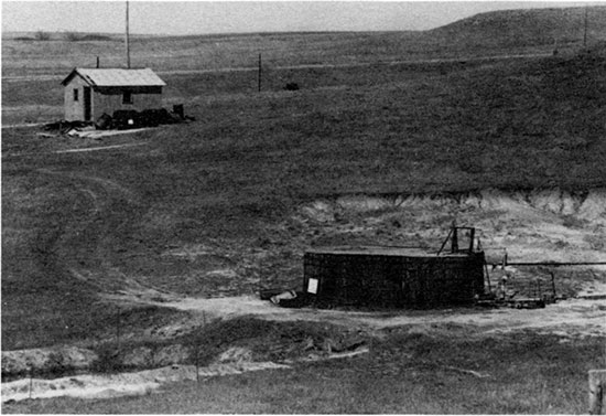
Deep disposal wells continue to be the preferred means of disposing the large volume of saltwater produced from the 550 to 450 stripper oil wells active during these years. Fig. 42 is a photograph of a typical deep saltwater-disposal well installation. The only visible evidence of the presence of a deep SWD well is the large receiving and settling tank often made of redwood and partly buried below ground level to permit gravity flow into the tank. A float valve releases the saltwater that flows by gravity into the well, requiring no pump or other equipment.
Figure 42--Photograph of a deep saltwater-disposal (SWD) installation. Disposal of brine into the Arbuckle formation, depth near 3,400 ft (102 m), is by gravity flow from the brine-storage tank. Courtesy Russell County Historical Society.
With the increase in the price of crude oil in the 1970's and 1980's (fig. 17), there was considerable activity in drilling infill wells on old leases, deepening or re-completing old oil wells, and the increased need for SWD facilities. Some of the 49 additional deep disposal wells were completed by reentry of abandoned oil wells or dry holes and deepening if the old holes had sufficient surface pipe left in place. Cost factors, demand by operators, and expediency caused the licensing of 33 additional shallow Cedar Hills Sandstone SWD wells in these years, bringing the total to 168 shallow SWD wells within the Gorham oil field. The policy of the regulatory agencies is to continue issuing permits for shallow wells disposing oil-field brines in the Cedar Hills Sandstone (except near the sinks affecting I-70), but to encourage operators to use deep Arbuckle SWD wells.
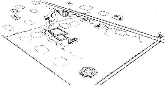
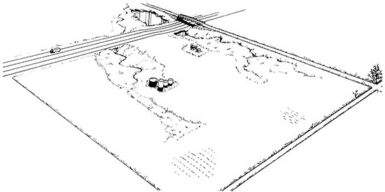
The sketch diagram (fig. 43) illustrates the 1986 situation in the Gorham oil field, where most of the oil wells are plugged and abandoned and the land restored to agriculture. I-70 from east to west across the sketch passes through the Crawford sink area, the subsidence of which is discussed in detail in the following section.
Figure 43--Roubach lease, 1986, with one remaining oil well. I-70, constructed in 1965-66r passes through the "Crawford sink." Subsidence affecting both the eastbound and the westbound lanes of I-70 and the bridge have been continuous since construction but at rates declining to 0.5 ft (15 cm) per year in 1986. Sketch by Steve Van Buskirk.
Subsidence
Introduction
I-70 has been subsiding in two areas, 0.5 mi (0.8 km) apart, within the Gorham oil field since construction of the highway in 1965 and 1966. Sinking has been slow (less than one foot per year) and is continuing (January 1, 1987). Subsidence to a level dangerous to traffic caused the rebuilding of I-70 in 1971 in both areas and again in 1986 in the west area. A third area is developing 0.5 mi (0.8 km) further east. It is anticipated that other subsidence areas will develop. The subsidence areas affecting I-70 are located exactly above the Topeka fracture zone described on p. 28-32 and illustrated in fig. 12. The subsidence areas are related to the fracture zone (Walters, 1978, p. 68-73).
History
Burgat and Taylor (1972), geologists with the Kansas Highway Commission during the construction of I-70, published an abstract, "Highway subsidence caused by salt solutioning." They named the subsidence areas "Witt" (west) and "Crawford" (east) after the names used on the adjacent oil leases which in tum were named from the landowners in the 1930's. Fader (1975) and Walters (1978) described the subsidence areas or "sinks." Steeples et al. (1986) published the results of their innovative shallow seismic programs. They employed a "CDP" or common depth point procedure through the subsidence areas in the Gorham oil field by shooting a continuous line along the ditch on the north side of the westbound lane of I-70 through the area pictured. in fig. 43. A second seismic line, next described, was recorded south to north along the section-line road with a bridge over I-70, also shown in fig. 43.
North-south seismic section
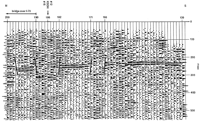
Fig. 44 is a seismic section furnished by Steeples et al. (1986) from their 1981 CDP seismic work. It is the south half of their unpublished north-south section. It extends from the north lane of I-70 south for 0.48 km (about 1,600 ft) along the section-line road west of the Crawford sink. Shotpoints, which are numbered from 139 to 200, are spaced at 8-m intervals (about 26 ft). The prominent reflecting bed. between 200 and 300 milliseconds, two-way travel time, is the Stone Corral anhydrite. At the south end of the section, shotpoints 139-166, the Stone Corral is undisturbed. except for a slight tilt to the north. At shotpoints 166 to 171, the Stone Corral is downfaulted. It is fragmented between the faults. From shotpoint 171 to 182, the Stone Corral anhydrite is downfaulted as a solid unit. In the interval from shotpoints 182 to 190, the Stone Corral is fragmented and dropped. The twin Crawford sinkhole wells, Numbers 16 and 12, with the Kansas State Department of Transportation's test hole between them are projected into the cross section from 330 ft (99 m) east as shown near shotpoint 186. From shotpoint 190 to 200 at the north end of the cross section, two faults, down to the south, have lowered blocks of Stone Corral anhydrite. The 225-ft (67.5-m)-long bridge over highway is built over these fault blocks. The bridge is under torque stress because it has subsided unequally, with the southeast corner lowered the most.
Figure 44--North-south seismic section along the section-line road, south from the bridge shown in fig. 43. The Stone Corral anhydrite (the reflection below the 200 msec travel-time mark) is faulted and downdropped through the Crawford sink. This previously unpublished seismic section was furnished by Steeples et al. (1986).
Cross section, I-70
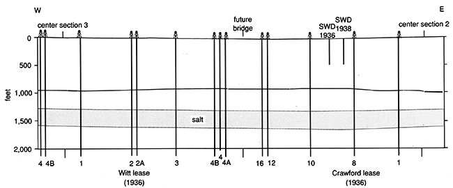
Fig. 45 is a west-to-east cross section along I-70, just over 1 mi (1.6 km) long. It shows what is known about sub-highway conditions for 2,000 ft (600 m) below the pavement. The cross section is based on the CDP seismic work of Steeples et al. (1986) recorded in 1980 as a continuous seismic-reflection survey performed along the north shoulder (westbound) of I-70. Their published seismic sections and their interpretations provide the basis for sketching the position and condition of the Permian Stone Corral anhydrite reflector, usually encountered near a depth of 900 ft unless downdropped by subsidence due to the removal of part of the underlying 3oo-ft (90-m)-thick Permian salt section present from 1,280 ft to 1,580 ft (384-474 m) where undissolved. Much dissolution of salt has occurred but this is usually not determinable from data recorded on the seismic sections. The partly dissolved salt section in fig. 45 is sketched diagrammatically by Walters. Steeples et al. (1986) were able to delineate the top and bottom of the Hutchinson salt only along that part of the line through the Crawford sink.
Figure 45--Cross section, 1981, along I-70 from west to east through the centers of secs. 3 and 2, T. 14 S., R. 15 W., showing subsurface conditions under I-70. The faulting is based on seismic work by Steeples et al. (1986). Their appraisal of future highway safety is summarized by words across the top of the cross section.
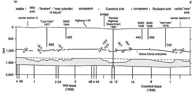
Across the top of the diagram are the interpretations of the sub-highway conditions by Steeples et al. (1986). These include 1) currently subsiding areas, the Witt sink, the Crawford sink, and the Roubach sink; 2) stable or competent areas not expected to subside; 3) an extensive broken area that is expected to subside in the future; and 4) an area at the east end of the cross section where subsurface seismic information suggests a future sinkhole not now manifest on the I-70 highway surface. The extensive area that is expected to subside in the future is east of the Witt sink and may become a portion of the Witt subsidence area.
In the upper portion of the cross section above the salt, three post-subsidence test holes and three early shallow SWD wells are projected into the cross section. For clarity none of the many former oil wells is shown in the area above the salt. The positions of the former oil wells adjacent to the south side of I-70 (eastbound) are shown below the salt by well numbers. The faulted condition of the Stone Corral anhydrite is based on the seismic survey. Downfaulted segments overlie areas from which salt has been dissolved by downward-flowing water or undersaturated oil-field brine. Surface subsidence at the Witt, Crawford, and Roubach localities is caused by subsidence of the anhydrite and other underlying rock layers due to the removal of salt by dissolution.
Fig. 46, a restored cross section through the same area as fig. 45, shows subsurface conditions in 1938 before dissolution of the salt section. Land surface on which the highway was built 20 years later in 1956 and 1957 is nearly flat. The Stone Corral anhydrite is unbroken, and the salt section is present in its full thickness of 300 ft (90 m). Surface conditions in 1938 are sketched in fig. 38 and in fig. 47.
Figure 46--Cross section, 1938, along the course of future I-70 as shown in fig. 45. The salt section is undissolved and the overlying rocks are intact and unfaulted. Surface conditions in 1938 are sketched in fig. 38.
Former oil wells; brine conduits or "sewers"
All the subsidence is salt-related and occurs above the salt. There is no disturbance of beds below the salt. The former oil wells were drilled in 1936 and 1937 with cable tools on 10-acre (4-hectare) locations, 660 ft (198 m) apart, with additional twin wells in the Crawford sink, near the Witt sink, and (not shown) within the Roubach sink. Most of these former oil wells are now plugged and abandoned, and often have corroded casing left above, within, and below the salt section. In most bore holes there is no cement or other plugging materials in the interval from the base of the salt to about 3,000 ft (900 m). The uncemented annular spaces outside of the oil-string casings provide conduits for downward-moving water. These former oil wells were the initial brine outlet or "sewer" needed for discharge of the long continued downward flow of freshwater or unsaturated brine across the salt section, thereby causing salt solution and- resulting in subsidence. Fader (1975) calculated that an average rate of flow of only 15 gallons per minute (0.95 L/s) for the 3O-year period from 1941 to 1970 would account for the salt dissolution causing the surface subsidence at the Crawford sink. He made similar computations for the Witt sink showing that only 5 gallons per minute (0.3 L/s) of water would be needed for 30 years to dissolve the amount of salt equivalent to the volume of the surface subsidence. In making these calculations he assumed that the volume of salt removed is equal to the volume of the subsidence and that the concentration of chloride in the downward-moving water changed from 3,000 to 150,000 ppm as the fluid circulated through the salt at a constant rate for the years 1941-1970.
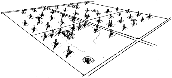
Fig. 47, by artist Steven Van Buskirk, visualizes the dense drilling in 1 mi2 (2.6 km2) of the area. It was drawn from a 1938 vertical air photograph. The view is toward the southwest. The 53 oil wells are marked by 53 derricks; they were erected on the spot in 1935-37 for drilling with cable tools. They were then left erect through the years for use as production derricks for pulling rods, tubing, and bottom-hole pumps. The drawing includes the northwest quarter of sec. 2 (nearest), the southwest quarter of sec. 2 (left), the northwest quarter of sec. 3 (right), and the southwest quarter of sec. 3, T. 14 S., R. 15 W. (most distant). I-70 now passes from left to right through the center of the drawing. The future Roubach subsidence area is at the left edge of the drawing; the Crawford in the center (twin oil wells in the northwest quarter of southwest quarter of sec. 2), and the Witt at the extreme right edge of the drawing. Each of these 53 cable-tool-drilled oil wells had oil-string casing originally uncemented for 2,700 ft (810 m) or more from the surface of the ground to the oil pay. Each was a potential conduit for the downward transport of freshwater or unsaturated brine across the face of the 300-ft (90-m) salt section from 1,200 to 1,500 ft (360-450 m) depth. Note the presence of six brine-storage "evaporation" ponds.
Figure 47--Sketch, 1938, W/2 sec. 2 and E/2 sec. 3, T. 14 S., R. 15 W. The Roubach lease is in the foreground. The future I-70 passes from left (east) to right (west) through the center of the drawing. The sketch shows the dense drilling in 1 mi2 (2.6 km2) with 53 oil wells marked by production derricks left in place after drilling with cable tools. The future Roubach sink is at the extreme left edge of the drawing, the future Crawford sink is in the center, and the future Witt subsidence area is at the right edge of the drawing. Each quarter section has one or more "evaporation ponds." Sketch by Steve Van Buskirk. View is toward the southwest.
Present shallow fracturing or brecciation
Evidence that the rocks in the sinkhole areas of Gorham are extensively fractured is also provided by three unsuccessful oil test holes drilled in or near sink areas in 1977, 1978, and 1981. All three resulted in "lost holes" and had to be abandoned at shallow depths. Two are shown on the cross section (fig. 45) and all three were mapped in fig. 40:
| In Witt sink, south of I-70 | In Roubach sink, north of I-70 |
|---|---|
| H & H Production Inc. Witt No. 9 70 ft (21 m) south of C N NW SE sec. 3, T. 14 S., R. 15 W. Lost circulation @ 400 ft (120 m) Lost hole @ 855 TD December 1977 |
Richard L. Mai Roubach No. 14 C W2 SE SE NW sec. 2, T. 14 S., R. 15 W. Lost circulation Lost hole @ 742 TD November 25,1978 |
The third is located a few feet east of the cross section and 330 ft (99 m) south of I-70. It is James A. Bolton Pierce No. 4 in the C N/2 NW SE sec. 2, T. 14 S., R. 15 W. Lost circulation resulted in a lost hole July 7, 1981.
The significance of complete and irrecoverable "lost circulation" in the three recent "lost holes," all close to I-70, is that they indicate that a major fracture system or brecciated area has formed where previously the rocks were solid. This means that for a stretch of about 1,200 ft (360 m) of I-70, between the Witt and Crawford sinkholes, settling and brecciation have occurred below the area of visible subsidence. Near the Roubach sink, which is barely visible on the highway surface, about 850 ft (255 m) of I-70 is similarly underlain by brecciated rock slumped into void space caused by dissolution of salt.
Drilling with rotary tools in highly fractured rocks
When circulation is lost while drilling with rotary tools, it may become difficult, dangerous, or sometimes impossible to continue drilling. The latter condition is cryptically designated as "lost hole," meaning abandonment of the hole. To support the significance of lost circulation and "lost hole" reports for test holes drilled in recent years near the Witt and Crawford sinks, rotary-drilling practices are briefly reviewed.
In rotary drilling, fluid is pumped down the inside of the rotated drill pipe through openings or nozzles in the bit, cooling the bit and flushing cuttings. The fluid, loaded with cuttings, is forced up the annular space between the drill pipe and the wall of the hole. This process is called "circulation." The drilling fluid, called "mud," then flows into a settling pit where the cuttings drop out due to slower velocity through the pit area. Drilling mud consists essentially of freshwater or saltwater with additives to control viscosity, gel strength, weight, and water loss. During routine drilling, the mud is recirculated without appreciable volume loss. Water and additional mudmaking materials are added as the hole depth increases. When circulation is "lost," fluid pumped down the hole does not return to the surface. Usually circulation is regained in a few hours by an addition of fibrous or platy "lost circulation" additives that form a wall cake, plugging off the pore space into which the fluid portion of the mud was infiltrating. This is not effective when systems of larger voids or fractures are encountered.
Large open voids capable of causing a hole to be lost include 1) fracture systems, which are defined as connected cracks of any kind, large or small; 2) faults, which are fractures with movement of one wall relative to the other; and 3) cavernous porosity such as caves in limestone. Drilling into fracture or cavernous porosity can cause immediate and drastic loss of circulation. If the fractures are sufficiently wide and interconnected, called a "reticulated fracture system" or "brecciated area," or if cavernous porosity of large volume is encountered, it may become impossible to stop the loss of circulation. All manner of particulate or fibrous material, including entire hay stacks, have been used in unsuccessful attempts to control this class of lost circulation. With no returns at the surface, the bit may become improperly cooled, cuttings are not flushed away from the drilling surface, and the hole walls may collapse or cave in. Some combination of these factors at times causes stuck drill pipe. These are the conditions described as dangerous to impossible, resulting in the "lost hole" notation on well cards. The presence of three such lost holes along I-70 (and their absence or scarcity elsewhere) is evidence of the collapsed and broken conditions underlying the portions of I-70 that are subsiding or will be subsiding in the future.
Volume of salt dissolved
A 1957 photo shows a pond at the location of the abandoned twin wells, Crawford No. 12 and Crawford No. 16, indicating subsidence. These twin wells encountered the Stone Corral anhydrite at depths of 904 and 901 ft (271 and 270 m) when drilled in 1937. Thirty years later, in August 1967, the Highway Department well drilled between them encountered the anhydrite at 938 ft (281 m) or a drop of 34 ft (10 m). The 1980 seismic work (Steeples et al., 1986) north of the twin well locations at the center of the sinkhole indicates that "approximately 50% of the salt has been dissolved beneath the highway at the point of maximum drop in the Stone Corral. This compares favorably with a 40% dissolution estimate obtained by drilling done by the Highway Department in 1967." One-half of the 280 ft (84 m) of salt drilled in the Crawford No. 16 borehole from 1,265 to 1,545 ft (380-464 m) equals 140 ft (42 m) of salt removed.
At the Witt sink, downdropping of the Stone Corral anhydrite was confirmed on January 12, 1986, on the log of the Witt 1-A drilled by the Kansas Department of Transportation 4 ft (1 m) west of the original Witt No. 1. In the 1986 hole, the Stone Corral was encountered at a depth of 946 ft (284 m), or an elevation of 928.5 ft (279 m) above sea level, compared to its position in the original Witt oil well at an elevation of +969.0 ft (291 m) in 1936. This is a drop of 40.5 ft (12 m). Steeples et al. (1986) comment on the conditions in and adjacent to the Witt subsidence area: "The area to the west of the Witt sink contains competent rock at all depths to well below the salt." To the east, however, for a distance of 400 m (1,320 ft), "The Stone Corral reflections exhibit incoherent or broken-up characteristics," and "may subside in the future." In the Witt sink area, the position and thickness of the salt section cannot be interpreted from the seismic information. However, Don Butcher (personal communication, December 26, 1989), who supervised the 1985-86 drilling of the Witt A-1, stated that "solid salt" was drilled at 1,387 ft (416 m). This is 95 ft (29 m) lower than its position in the original hole. Above the "solid salt" the interval from 1,320 to 1,387 ft (396-416 m) drilled rapidly, is shaly on the gamma log, and was called "washed salt" by Butcher. The author interprets that section as collapsed rubble including some residual partly dissolved salt.
As shown in fig. 45, the Stone Corral is downfaulted under all four sink areas on the eastwest cross section (fig. 45) as compared with its original undisturbed position prior to the salt dissolution (fig. 46), but the volume of salt dissolved cannot be measured from the seismic work.
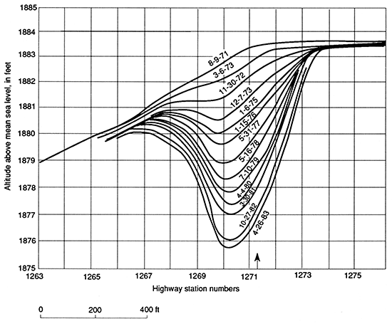
Figure 48--Graph of the subsidence at Witt sink, eastbound lane, 1971-1983. Vertical exaggeration x100. Subsidence measurements are recorded in the appendix, table 7, p. 102. This portion of I-70 was rebuilt in 1985 to the 1971 grade. Data courtesy of the former Kansas State Highway Commission. Arrow shows projected location of twin oil wells.
Highway subsidence--amount, rate, trend, and cost
In 1966 the Kansas State Highway Commission initiated a program of regular, precise elevation surveys to the nearest one-hundredth of a foot along the midline of both the eastbound and the westbound lanes of I-70. The successor agency, the Kansas Department of Transportation, continued surveys and furnished data to April 26, 1983. Table 7 in the appendix summarizes subsidence data in the three sinking areas: Witt sink, Crawford sink, and Roubach sink.
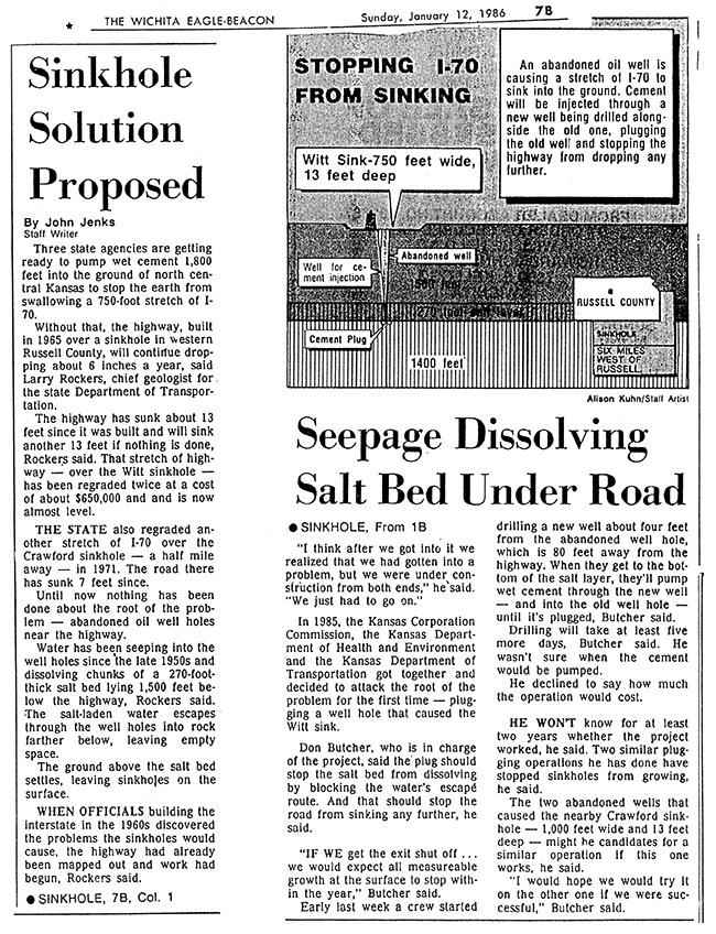
Highway subsidence in the Witt sink is shown diagrammatically in fig. 48 with a vertical exaggeration x100. The time period involved extends from the rebuilding of the highway in the summer of 1971 (after sinking 4 ft [1.2 m]) until April 26, 1983. The sinking of the highway, as shown, created a sag causing a car or truck to suddenly disappear from view of the following vehicle, a hazardous condition. Rain water collected in the sag. Runoff eroded a gulley in the south shoulder. The gulley led directly to the sunken casing of the abandoned oil well Witt #1, where the rain water disappeared down the outside of the casing, presumably causing additional salt dissolution and subsidence. Because of these conditions, it was necessary to rebuild I-70 in 1985 in the vicinity of the Witt sink. During 1985 and continuing into 1986, the Kansas Department of Transportation with the support and advice of the Kansas Corporation Commission and the Kansas Geological Survey undertook a remedial operation to plug off the "sewer," or brine outlet, as a means to prevent future subsidence. A newspaper article from the Wichita Eagle-Beacon, January 12, 1986, is reproduced as fig. 49. Don Butcher, geologist with the KCC who was in charge of the drilling project, furnished his final report (personal communication, September 1988). In it he states that the rate of subsidence affecting I-70 in the Witt sink after repair was 0.50 ft (12.5 cm) in 1986 and 0.40 ft (10 cm) in 1987. The cumulative subsidence affecting the eastbound lane at the Witt sink is about 13 ft (3.9 m); at the Crawford sink, about the same amount; at the Roubach less than 1 ft (0.3 m); and at the new sink none.
Figure 49--Facsimile of a news item in Wichita Eagle-Beacon, Sunday, January 12, 1986, describing remedial work in the Witt subsidence area. Reprinted with permission of the Wichita Eagle-Beacon. Copyright January 12, 1986, The Wichita Eagle and Beacon Publishing Company.
It is significant that the rate of subsidence is diminishing over the 21-year period for which measurements are available. The average rate of subsidence in the two major sinking areas has declined to less than 0.4/ft per year (or about 5 inches [12.5 cm]). Subsidence rates have declined nearly 50%. This is an encouraging trend.
These seemingly minor amounts of subsidence, measuring only a few inches per year, have cost nearly one million dollars in highway repair, including about $650,000 at the Witt sink in 1985, and $250,000 at the Crawford and Witt sinks in 1971.
While subsidence is continuing (January 1, 1988), there is less cause for concern about safe use of the highway than in the past because the elevation surveys confirm a diminishing rate of subsidence, table 7, p. 102. It is anticipated that slow but not catastrophic subsidence will continue.
Future subsidence along I-70
Future slow subsidence is anticipated along I-70, particularly in the area east of the Witt sink labeled in fig. 45 as "broken--may subside in future." The broken, fragmented condition of the Stone Corral as recorded in the seismic work is similar to the fragmented condition of the Stone Corral beneath the present Witt and Crawford sinks. It is different from the competent areas where the seismic work shows solid, unbroken Stone Corral anhydrite. The presence of a lost hole, depth near 885 ft (266 m), confirms the fractured or brecciated subsurface condition. A second factor contributing to slow subsidence in the future is the continued compaction of the fractured and brecciated rock above and below the Stone Corral anhydrite. A third factor contributing to future slow subsidence of I-70 concerns the Cedar Hills-Cheyenne common aquifer, depths 341 ft to about 600 ft (102-180 m). That common aquifer is over-pressured due to recharge from shallow SWD wells disposing oil-field brines into it in the past and continuing to the present. One shallow SWD well in the future subsidence area, completed in 1944 at a depth of 420 ft (126 m), is shown in fig. 45. The recharged common aquifer is expected to continue discharging downward through the previously used channels, fractures, or improperly plugged well bores, dissolving more salt, causing more slumping, and causing continued slow surface subsidence of I-70 in the area marked "may subside in the future." It is expected that the subsidence will continue to be less than 0.40 ft (10 cm) per year. The salt section is being dissolved from the top, according to drilling evidence and seismic evidence, and not from the bottom or from the mid-part of the salt section as is the case during commercial solution mining of salt. Over a broad area beneath I-70, the resulting void space has spans exceeding the beam strength of the weak shale roof rock that sags into the void almost simultaneously with its formation. The sagging and fallen roof rock, by its own bulking, provides partial roof support limiting upward subsidence to beddingplane separations in decreasing amounts upward, resulting in surface subsidence measured in inches per year.
Research drilling and coring in other salt-related subsidence areas in Kansas
In 1977 through 1980, research drilling and coring programs were conducted at three salt-related subsidence areas in Hutchinson, Kansas, by the Solution Mining Research Institute, an international organization supported by companies engaged in the commercial mining of salt by solution. The principal investigator was Dr. Alfred J. Hendron, Jr.
The first area in which research test holes, both vertical and inclined, were cored, drilled, and logged was at Cargill, Inc., south of the plant, in a large, 90,000-yd3 (68,400-m3) subsidence area. The surface expression formed in three days in October 1974 (Hendron et al., 1977) and (Walters, 1978). The second area of research coring was also at Cargill Inc., but north of the plant where 26 years of slow subsidence at a rate of a few inches a year involved the driveway, parking area, loading dock, and plant warehouse (Hendron et al., 1979a). The third area of vertical and inclined drilling and coring was at the Carey Salt Co. brine field, where two small related subsidence areas 700 ft (210 m) apart formed in three days in June 1978 (Hendron et al., 1980, 1983) and (Walters, 1979). From these field investigations, Hendron et al. (1979b) reached general conclusions that rock mechanisms resulting in surface sinkholes involved 1) broad unsupported spans, 2) a large salt cavity, 3) a trigger mechanism such as brine-pressure change or removal of critical roof support by continuing salt dissolution, and 4) in situ stress conditions in the roof rocks. They concluded that where all four conditions are present in proper proportions, deep sinkholes are likely to develop at the surface in very short periods of time (8-20 hours). If only the first and third conditions are present, shallow sinkholes are likely to develop slowly on the ground surface. Their depth and lateral extent tend to increase in a time span of years. The situation at I-70 in the Gorham oil field fits well with their criteria for slow shallow, long-continued surface subsidence.
Subsidence at a deep saltwater-disposal well
Subsidence in another portion of the Gorham oil field occurred around a deep SWD well in 1982. The area around the well was lowered 9 ft (2.7 m). A large saltwater settling tank was tilted inward toward the well. The location, in the NE SW SE sec. 32, T. 14 S., R. 14 W., is in a flat field sloping slightly to the north. The field is underlain by alluvium deposited on the Pleistocene floodplain of the Smoky Hill River, 0.5 mi (0.8 km) northwest. The subsidence area, centered around the former SWD well, was 600 ft (180 m) in diameter and circular. Because the SWD well was located 1,650 ft (495 m) west and 990 ft (297 m) north of roads along the east and south sides of sec. 32, there is no surface damage other than to the SWD well itself and to the tilted tank.
The SWD well, the Billings No. 1, drilled into Arbuckle dolomite at 3,180 (-1,453) ft (954 m) in 1953 with 5-1/2-inch (13.75-cm) casing set at 3,235 ft (971 m). Under a permit from KCC, oil-field brines were disposed into the Arbuckle and Reagan sand from 3,235 to 3,370 ft TD (970-1,011 m). Precambrian basement is estimated to be near 3,405 ft (1,022 m).
The Kansas Geological Survey surveyed a west-to-east surface-elevation profile (Don Steeples, personal communication, 1982) on September 15, 1982, as part of a gravity survey. The survey stakes were still in place October 1, 1982, when the author visited the location. The results of the limited gravity survey were inconclusive. In order to properly plug the well to protect the freshwater aquifer in the alluvium, it was necessary to construct a ramp into the sink area and to drill a hole close to the slumped 5-1/2-inch (13.75-cm) casing of the SWD well. Don Butcher, who supervised the plugging (personal communication, 1988), stated that coarse alluvial sand which downdropped as a result of the subsidence was still being encountered at 300 ft (90 m), the total depth of the relief hole into which cement was pumped. The saltwater-disposal well has been plugged, the location leveled, and the field restored to agriculture.
Although there are 49 deep SWD wells in the Gorham oil field (fig. 2), no other subsidence areas were reported as of January 1, 1987.
Conclusion--subsidence areas
The subsidence around the Billings No. 1 SWD well and the subsidence areas described as affecting I-70 are adverse environmental consequences of the development of the 60-year-old Gorham oil field.
Agriculture
Impact of the Gorham oil field on agriculture
Much of the 50 mi2 (130 km2) within the official boundary of the Gorham oil field is agricultural land largely devoted to growing wheat. The oil-field boundaries are defined in the index map (fig. 3) and in fig. 50, the map of active oil wells as of October 1986. No map is included specifically showing agricultural lands, but fig. 16, the map of the Fencepost limestone, provides an approximation. In the northern part of that map, heavy outcrop lines in a continuous crinkled pattern mark the change from canyon country, largely pasture, on the north to fairly flat farmland on the south. In the extreme southwest portion of the map, the Fence-post limestone crops out in an area of gentle hills. Much of the farmland within the Gorham oil field is a fairly flat but dissected plain or is part of the valleys of Big Creek and the Smoky Hill River.
Figure 50--Map of the Gorham oil field, 1986, showing the location of the 444 remaining active oil wells as of December 31,1986. Compare with oil-field map, fig. 2, p. 3.
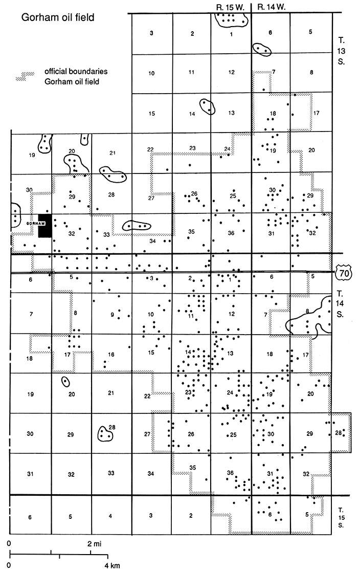
During the many years of drilling, completion, red rilling, and production of oil there was considerable interference with normal farming operations. With the plugging of many old holes, the area is being restored to agriculture. A person driving along I-70 or on any of the section-line roads sees but infrequent reminders of the once-extensive oil field. Even though 444 oil wells were still active in October 1986, as mapped in fig. 50, there are large areas where a tourist would not know there had been oil production. Gone are the derricks, once the symbols of an oil field. Gone too, are most of the tank batteries and the roads leading to them and to the many now-abandoned oil wells.
When the land is viewed on a more detailed scale, many areas of an acre or two are damaged. Land on which tank batteries were formerly located may have an accumulation of oily bottom sediment dumped when cleaning oil-storage tanks. Former lease roads, even after they are ripped up, may be more compacted than the surrounding field. Metallic junk left in weed patches or buried under a shallow cover of soil is a hazard for farm equipment. In a few areas of remote pasture, the four cement derrick foundation blocks have been left in place since the wells were abandoned 30 years ago. Examples of unremoved derrick foundation blocks occur along the south line of sec. 10 and the north line of the adjacent sec. 15, T. 14 S., R. 15 W., where the road between the two sections is closed and there is access only by private road.
The quantitative impact of the formerly more extensive Gorham oil field on agriculture has not been investigated as a part of this study. Four U.S. Geological Survey 7-1/2-minute topographic maps surveyed in 1961, contour interval 10 ft, scale 1:24,000, are available. They are the Gorham, Russell Northwest, Walker, and Russell Southwest quadrangles. Detailed large-scale air photographs which are used by government agencies in quantitative assessment work, were reviewed. These detailed maps or photomosaics are available as blueline prints, scale 1 inch = 400 ft. Each section (square mile) is a little more than 13 inches square. They show each building, road, trail, oil well, pit, etc. The date of the photography is February 1986. Also available are soil-survey maps, scale 1:20,000, compiled from 1981 photographs (Jantz et al., 1982).
One concern regarding agriculture was the extensive use of unlined earthen pits during drilling operations through the 60 years of the Gorham oil field. In this connection, the 1,827 deep test holes drilled for oil and gas and the 168 shallow SWD wells had one or more pits for water storage during drilling and for accumulation of well cuttings. These were unlined earthen pits, filled only once for time periods of days or weeks, causing minimal salt contamination. No steel tanks were used for pits as is required in some urban areas. Almost all these former pits were filled in order to not interfere with later farming operations. To be properly filled, a pit needs to be left until absolutely dry, which may take half a year, then filled with dry material. Oil-field operators know this and follow this procedure. Occasionally landowners become impatient and demand immediate filling of pits. When such pits are filled while still wet, they can remain a hazard for years with tractors used in farming operations sinking into them.
The extensive shallow saltwater-evaporation ponds in use in the 1930's and 1940's have been filled and leveled. They have more impact on agriculture than the pits used for drilling with rotary tools or the single pit into which cable-tool well cuttings were dumped. Evaporation ponds were filled and then refilled over periods of months to years and decades, accumulating concentrations of residual salts. Evaporation of water from those extensive evaporation ponds did not decrease the potential contamination of aquifers or soils because the dissolved salts remained after evaporation of water, either dissolved in more concentrated brines, or, with complete evaporation, as salt crusts. In addition, from time to time rain water redissolved the salts. The resulting brine either ran off or infiltrated as ground water. Where the now-filled abandoned ponds have residual salts buried within reach of plant root systems, crop production is impaired. The residual salts are drawn to the surface in drought years or flushed deeper in wet years. They adversely affect growing crops for long time periods. For example, the area of the former twin saltwater ponds on the much cited Roubach lease, the NW sec. 2, T. 14 S., R. 15 W., is now a salty waste land.
Summary--environmental impact of the Gorham oil field
The environmental impact of the Gorham oil field was not measured quantitatively. The area is being restored to agriculture with pits filled, tank battery dikes leveled, and lease roads ripped up, but areas of one acre or more that were sites of former "evaporation ponds" are damaged by increased salinity of the soil. In addition there is some local saline pollution of former freshwater aquifers and continued costly slow subsidence of I-70. Less environmental damage was due to the mishandling of crude oil, a valued product, than was due to mishandling of saltwater, a waste product. The production of almost 100 million barrels of crude oil, and perhaps 10 times that volume of associated brine, has unfavorably affected the 50-mi2 (150-km2) area of the Gorham oil field. Rigorous regulation by the Kansas Corporation Commission is being directed toward minimizing future adverse environmental impact on the area due to oil-field operations in the nearly depleted Gorham oil field.
Prev Page--History || Next Page--Summary, Appendix, References
Kansas Geological Survey, Geology
Placed on web Jan. 30, 2015; originally published 1991.
Comments to webadmin@kgs.ku.edu
The URL for this page is http://www.kgs.ku.edu/Publications/Bulletins/228/06_envi.html