![]()
Prev Page--Salt Deposits of Kansas || Next Page--Oil and Gas Operations
Part II: Land Subsidence Areas Associated with Salt Mining
Hutchinson, Kansas: Local Geology--Salt Resources
Unconsolidated Pleistocene beds
Underlying the city of Hutchinson, Kansas, below eight feet of bess-like soil, are coarse crossbedded loose sands and gravels having a thickness of 50 feet or more. These alluvial sands of the McPherson Formation (formerly called the McPherson Equus Beds) were deposited as stream-channel filling during various epochs of the Pleistocene. They have been extensively drilled to provide the municipal water supply for the city of Hutchinson (Williams, 1946; Bayne, 1956) and, further east, for the city of Wichita (Williams and Lob-man, 1949). The presence of an abundant supply of fresh water was and is an important factor in salt mining by solution. At the Cargill plant, three water supply wells, each capable of supplying 1,000 gallons per minute with very little drawdown, are typical of water wells in the vicinity. These shallow beds are designated by stippling in Cross Section A-B, Figure 2.
Bedrock; Permian formations
Bedrock is Permian shale, commonly reddish brown. This extends to depths near 400 feet east of Hutchinson, or 500 feet southwest of the city. Beneath the Permian shales are salt beds with a thickness of about 350 feet. Under the salt beds are massive anhydrites interbedded with clay shales which extend to the top of the Chase Group marked by the presence of normal marine beds of the Nolans limestone. With reference to the regional Cross Section A-B, Figure 2, all Permian rocks are designated "P." The Chase Group is designated P-6. Beds designated P-5, P-4, P-3, and P-2 constitute the Sumner Group. Within this group the Wellington Formation includes P-5, the shale and anhydrite beds below the salt, P-4, the Hutchinson Salt Member of the Permian Wellington Formation, and P-3, the shales above the salt. Elsewhere the top of the Wellington Formation is marked by the Milan limestone which is absent in the Hutchinson area, making it difficult to distinguish shale beds of the Wellington Formation which are dark colored in the lower portion just above the salt but which are reddish in the upper beds from the overlying red shales and siltstones, P-2, of the Ninnescah shale. The uppermost bed of the Ninnescah Formation, and of the Sumner Group, is the Stone Corral Formation (dolomite-anhydrite) which crops out between Hutchinson and Lyons, Kansas. The uppermost Permian beds in the area of Cross Section A-B, designated P-1, include redbeds of the Nippewalla Group which are unconformably truncated by Cretaceous beds, undifferentiated in Figure 2 but designated "C."
Salt resources
The local salt resources of the Hutchinson area are excellent and include 350 feet of horizontally bedded salt with interbeds of dark shale, and with a few thin anhydrite layers. The salt section is well shown in logs of the newly drilled Cargill brine wells in the E2 SW of Section 19, Township 23 South, Range 5 West. There the Hutchinson Salt Member is 80 percent salt (halite) and 20 percent insoluble nonsalt beds, shale, anhydrite, and dolomite. The resolving power of the available gamma-neutron logs is about one foot, the thinnest unit used, as contrasted with one inch minimum unit measured by Jones (1965) when he determined the content of the 282-foot thick Hutchinson Salt in the HNAS No. 1, seven miles south, to be 82 percent halite, 3 percent anhydrite, 4 percent dolomite-magnesite, and 11 percent shale and siltstone.
Wire line geophysical logs
Reasonably accurate salt resource determinations can be made from wire line geophysical logs if sufficient logs are recorded and if basic core examination work such as that of Jones has been recorded. A few comments are included here on the characteristics and usefulness for salt evaluation of wire line geophysical logs. It is suggested that the reader refer to Figure 6 and Figure 7 showing logs from AEC Test Hole No. 1 in the Lyons area used here because no comparable suite of logs is known to be recorded in collection with salt operations in the Hutchinson area.
The gamma-ray log (Fig. 6, "gamma") is by far the single most useful log in Kansas where halite beds are interbedded with shale. The gamma-ray radioactivity log can be recorded in both open holes and through casing. It discriminates readily between non-radioactive halite (left) and radioactive shale (right). In areas such as New Mexico, it can be used to distinguish radioactive potash salts. The neutron log (Fig. 6, "neutron") is everywhere quite useful in salt studies. It can be recorded in either open hole or cased holes. In areas such as Michigan, where shales are rare in the evaporite section, the neutron log is the single most useful log as it distinguishes readily between porous formations such as dolomite (left) versus nonporous salt (right). The neutron log is extremely sensitive to variations in borehole diameter and fails to record in enlarged holes, a factor which in itself aids in recognition of salt in rotary drilled oil and gas holes, and which is useful to indicate cavernous conditions behind casing in brine wells. The particularly sensitive neutron log depicted in Figure 6 is designed for open hole logging and minimizes borehole effects because it is a sidewall device mounted on a skid pressed against the side of the hole.
The density log, Figure 6, like the gamma and neutron logs, records radioactivity increasing to the right. It is au open hole log useful both as a porosity logging tool and in identification of minerals in evaporite deposits, but is used much less frequently. The density log is commonly plotted to the right of the lithology column but this less familiar log is here moved to the left side of the lithology column to show its similarity to the gamma log in salt and shale, and its discriminating dissimilarity in anhydrites. The various resistivity logs (Fig. 7) are open hole logs abundantly recorded in oil and gas operations as porosity tools and hydrocarbon-sensitive indicators. Resistivity logs are useful in salt studies because bedded evaporites are essentially nonporous and electrically nonconductive, hence are characterized by extremely high readings on resistivity logs. The laterolog illustrated in Figure 7 has special shielding to minimize the influence of borehole size and to permit recording of resistivity through salty muds.
The sonic log (Fig. 7, "BHC Sonic") is also extremely sensitive to borehole size, hence is "BHC" or "borehole corrected" using the simultaneously recorded caliper log, showing hole size in inches, for corrections. A cross plot of sonic and neutron logs permits the determination of several non-radioactive evaporite minerals. Moreover some evaporites can be identified specifically from time sonic log alone by their sound travel times or velocities, for example, halite 15,000 ft/sec = Δt of 67 on the log and anhydrite 10,000 ft/sec = Δt of 50 n the log where the formations have sufficient thickness to record. In New Mexico where natural salt dissolution (subrosion) has occurred from the surface downward, not just at the salt edge as in Kansas, the dissolution of a salt bed may leave an air-filled porous zone affecting the travel time of sound waves; hence sonic (sometimes called acoustic) logs have indicated the position within the section of a missing salt bed. Other sonic logs also recorded in AEC Test Hole No. 1, but not here illustrated, record acoustic amplitude variations in the compressional or in the shear waves and have applications in determining cement bonding, cement compressive strength, abnormal formation pressures, and in combination with precise caliper logs and density logs can be read and computer-calculated to yield data on shear modulus, Young's modulus, and Poisson ratio. These more exotic sound wave logs ("variable density log," "frac finder log," "3-D velocity log," etc.) are not now used in salt-related drilling but in the future may become more widely applied for rock mechanics studies, particularly for the in situ evaluation of the strength of roof rocks overlying salt cavities.
Roof rocks above the Hutchinson Salt
Any discussion of the salt resources of the Hutchinson area must include a consideration of the roof rocks above the salt beds. The Permian Wellington shales, thickness 340 feet or more, just above the salt section, provide a poor roof rock which has failed repeatedly when sufficiently undermined leading to surface subsidence over salt cavities. The basal dark-colored shales, 20 feet or so in thickness, immediately overlying the uppermost salt bed have joint and bedding cracks filled with one-fourth inch bands of red halite. These shales were deposited as muds in an evaporite environment. Their halite-filled mud cracks and their illite clay minerals indicate equilibrium with salt brines, but these shales slake, slough, and cave readily when exposed to air or to fresh water. In old brine wells, where casing was set at the top of the salt or above the salt in the shale beds themselves, cavernous conditions behind the casing are common as recorded on cased hole neutron logs, indicating roof rock collapse of these shale beds.
Shallower red shales and reddish-brown siltstones of the Wellington Formation, termed "redbeds," likewise are unstable when exposed to fresh water and make a poor roof rock susceptible to sloughing and collapse. The clay minerals (Swineford, 1955) in these redbeds are largely illite and chlorite, not kaolinite, indicating deposition under water in a broad saline basin. The Permian redbeds are about as impermeable to water as any formation, a factor vital in preserving the Wellington Salt, but such redbeds "cave" readily in boreholes when drilled with fresh water and form poor quality roof rock, with the result that surface subsidence as described in this report has occurred due to dissolution of salt at depths greater than 1000 feet in oil and gas test holes in central Kansas as a result of roof failure in the Wellington shales.
Relation of roof rock failure to method of salt mining
Land subsidence is found to be directly related to roof rock failure caused by the formerly used method of solution milling of salt through single boreholes with casing set in the shales above the salt and tubing extending into the salt section. Maximum salt dissolution occurred in the most shallow salt beds, with the cavity often developing a "morning glory" shape broadest at the top. Extended operation of these wells or groups of wells (galleries) undermined large areas, often beyond the structural competence of the shale roof rocks. Modern methods are directed to minimizing this roof span or limiting it to the competence of the rocks for the spans developed. The relation of each of four mining methods to roof rock failure is summarized as follows:
| Mining Method | Portion of Salt Mined | Associated Surface Subsidence |
|---|---|---|
| Underground Mines | One bed 8' to 15' thick in lower salt; room and pillar with 75% of salt removed. | None known |
| Solution Mining 1888-1960s |
Predominately the uppermost salt decreasing downward. | Known surface subsidences in 1914, 1915, 1952, 1974 |
| Solution Mining 1960s-1970s |
Predominately the lowermost salt decreasing upward. Void space is a narrow corridor. | None known |
| Solution Mining for storage of Liquefied Petroleum Gas | Lower salt below "shale" marker; 100'± vertically, 40± diameter. | None known |
Where underground mining of a single salt bed was done by the "dry" method, or room and pillar mining, leaving 40 percent to 25 percent of the salt as pillars, no known surface subsidence has resulted in Kansas. With the passage of a few years' time, the inactive areas of underground mines tend to close by flowage of rock salt iml the pillars as described by Dellwig (1958), but with mine ceiling of only 8 to 11 feet, and mine floor depths of 645 feet (Hutchinson area) to 1024 feet (Lyons area), no surface subsidence has been noticed. Likewise, no surface subsidence has been recorded in connection with the operation of hundreds of LPG storage cavities dissolved in salt. Commonly, these are dissolved through a vertical range of 100 feet in the lower portion of the salt, leaving perhaps 200 feet of salt roof rock. Moreover, most LPG storage cavities are about 40 feet in diameter spaced on 100-foot centers, leaving about 88 percent of the salt unmined throughout their average height of 100 feet.
Brine production by operation of single individual wells, termed "conventional wells" by Landes and Piper (1972), was the system extensively used from 1888 until the 1960s, and cases are known of present-day, single-well operations. In this method of operation, casing was set at the top of the salt and a string of tubing lowered to the bottom of the salt section to be brined. Water pressure at the surface provides the energy to lift the resulting saturated brine back to the surface.
A pressure tight cavity is required, a condition usually prevailing in the early life of a well. By this method of operation, salt was dissolved upward in the salt zone with extended operation due to the buoyant rise of fresh water (or weak recycle brine). This in turn caused the tubing to be broken as the result of the falling of undermined ledges (shale, anhydrite) which then exposed shallower salt beds, the dissolving of which allowed water direct access to the roof; dissolving concentrated at the top of the cavity which in near horizontal beds developed a conical or morning glory shape. Ultimately, cavities merged with those of adjacent brine wells to form a common cavity known as a gallery, thus tremendously increasing the span of the unsupported roof. Carried to the strength limit of the overlying rocks, the cavity roof then sagged downward. Translated to the surface as down-warp, the effect initially was barely detectable. Under proper conditions, it affected surface drainage causing ponding. Action sometimes terminated at this point, or if dissolution continued and the gallery enlarged further, the undermined roof rock collapsed into the cavity layer-by-layer in a mechanism known as stoping. The end result of this former method of cavity operation is thus considered to be directly related to roof collapse and ultimately to localized surface subsidence including sinkhole formation.
Modern brine well systems are designed to assure surface stability by limiting roof spans. In the Hutchinson area for example, wells for salt production are often drilled in pairs on 400-foot centers. At least two pairs of wells on 1000-foot centers have been in operation since 1967. In one pair of these wells, 10 million cubic feet of salt have been dissolved in each of the wells, or a total of 20 million cubic feet (Mauritz J. Kallerud, personal communication, July 10, 1976). Wells in each pair have been connected at the base of the salt section by an undercutting technique known as hydraulic fracturing. By this method, water pumped into one well dissolves salt as it moves laterally toward the second well through the undercut or fracture zone. The resulting brine is returned to the surface through the second well. Dissolution continues; eventually enough salt is removed from the bed containing the cross connection that the overlying layer falls by undermining, and the water has access to the next higher salt bed. This is repeated as mining progresses; a channel or corridor is dissolved between the two wells. Structural stability depends on the competence of the roof rock and roof salt. The narrow span of the width dimension of a cavity provides the needed structural stability.
Hutchinson, Kansas: Early Land Subsidence Areas
Three known areas
In and near the city of Hutchinson, where salt has been mined continuously since 1888, only three areas of land subsidence earlier than the 1974 event pictured on the front cover are known to the author. All three are associated with salt mining by the former method of solution mining using casing set near or above the top of the salt, with resulting uncontrolled dissolution. The areas are listed in order as to time of subsidence:
| Year | Company | Area | Remarks |
|---|---|---|---|
| 1914 | Morton Salt Company |
Southwest of city |
Rapid surface cratering |
| 1925 | Carey Salt Company |
Downtown | Slow subsidence of only few inches |
| 1952 | Barton Salt Company |
Southeast of city, north of plant |
Ground subsidence with water coming in the hole |
It is quite possible that there are other areas. Old records become lost, the unrecorded locations of old brine wells are forgotten, and even land subsidence areas, which characteristically stabilize when mining ceases, are not remembered. On the other hand, the total amount of salt mined was much less than the 4,000 short tons per day mined in the State of Kansas in 1974 (Berendsen, 1975). Calculations from figures recorded by Taft (1946) for annual salt production for the entire State of Kansas (separate figures for the Hutchinson area are not given) indicate that the average daily salt production at the time of the 1914 subsidence was approximately 1,000 tons per day, and at the time of the 1925 subsidence was about 2,000 tons per day. It is estimated that at the time of the 1952 subsidence the figure was less than 3,000 tons per day. The three known areas are described in chronological sequence.
Morton Plant, 1914
On May 15, 1914, subsidence took place within the plant of the Joy Morton Salt Company southwest of Hutchinson. The company's plant and solution mining operations are located just south of the Arkansas River in Section 23, Township 23 South, Range 6 West (Fig. 2--near Well 14). Conditions are comparable to those at the Cargill plant (Fig. 2--Well 15) except that the salt is somewhat deeper, being encountered near 500 feet.
According to a contemporary report dated May 25, 1914, by Erasmus Haworth, State Geologist for Kansas (from the Morton Company files, Mauritz J. Kallerud, personal communication, June 8, 1976), "On the morning of the 15th inst., at about seven o'clock, a depression became noticeable in the surface of the ground within the works. By ten or eleven o'clock, the depression had reached a maximum (vertical depth) of fifteen feet, carrying with it and demolishing certain parts of the plant. . . . The border of the sunken area approximates a circle of about 150 feet in diameter. Wells No. 1, No. 2 and No. 3 are close to the border of the sink, and each one was affected. . . . Well No. 1 had both casing and tubing broken off at 287 feet. ... After the sinking, a sand bucket was let down into No. 2 175 feet but would go no further, and a like sand bucket could be sunk 185 feet in No. 3. The ground sank enough to carry top of drive pipe 8 feet below original surface, with the casing pulled down four feet further than the drive pipe, although the space between the two was thoroughly packed with rope packing to make a water tight joint."
After the initial rapid subsidence, the sinkhole was filled and leveled with sand, and the affected brine wells were abandoned and plugged. The ground has stabilized as indicated by over 50 years of close monitoring by surveying the position of the tall brick smoke stack located immediately adjacent (25 feet ±) to the ground affected by the sinkhole.
Carey Salt Company, 1925
An excellent account by C. M. Young (1926) entitled "Subsidence Around a Salt Well" provides information and precise settlement measurements of gentle early subsidence in downtown Hutchinson in 1925, centering around Well 2 of the Carey Salt Company. Maximum subsidence reported by Young was about two and one-half feet vertically and one-fourth foot horizontally. Raymond C. Moore (1925) states in an open-file report dated March 25, 1925: "except for its occurrence in the city where paving and large buildings have shown the effects of the movement, it would have been certainly quite unnoted." Measurements by the city and county engineers showed a series of cracks in the pavements of streets and alleys outlining a circle about 600 feet in diameter. Most serious damage concerned the former court house which stood upon a line of surface cracks indicating tension. The east end of the court house moved horizontally away from the undisturbed west end by about 2 1/2 inches.
The cement collar of the abandoned Well 2 may still be seen at the southwest corner of the intersection of Walnut Street and the paved alley midway between Avenue B and Avenue C, but the obsolete court house and other structures have been razed. The area has stabilized and is presently the site of a supermarket. Well 2, first used as a brine production well, was later used as a fresh water input well supplying brine Well 1, 246 feet west, and brine Well 3, 254 feet east, with which it was connected presumably in a common cavity or gallery. All wells were abandoned at the time of the settlement, and the Carey Salt Company continued the gradual transfer of its salt well operations to its present location east of the city. There had been a growing recognition in Hutchinson since the 1914 Morton subsidence, that the extraction of large quantities of salt posed a risk of surface subsidence, and hence that the downtown urban area was an undesirable place for salt mining. The early detection of the initial laud subsidence in downtown Hutchinson in 1925, the careful monitoring work reported by Young, and the publicity discussed above caused the immediate cessation of solution ruining in this area. This work by Young serves as a documented example of early detection of subsidence by detailed surveying. Cessation of operations no doubt precluded further subsidence which might have caused damage to valuable urban property.
Barton Salt Company plant, 1952
In June 1952, the ground north of the Barton Salt Company plant in the NW of Section 19, Township 23 South, Range 5 West, began subsiding around au old G&H Salt Company well. Remnants of this subsidence may be seen in the abandoned spur of railroad track and the nearby steep crater wail still showing more than ten feet of relief. At the the of the sinking it was noticed that Barton Salt Company's Well 60, south of the plant (Figs. 8 and 9), more than 1,000 feet distant, was associated with the caving north of the plant where water was seen to be coming in the bottom of the hole, until Well 60 was cut off. The operators suspected that their Wells 7, 8, 58, and 59 were also associated with the dissolution gallery connecting the G&H subsidence area with Well 60.
The old G&H Salt Company well (the exact location is not known to the author) may have been drilled in 1888 as one of the wells of the firm of Dr. W. C. Gouinlock and C. H. Humphrey. Their firm was the first to begin salt operations at Hutchinson, according to Eskew (1948). When the G&H brine well was re-entered and plugged in June 1952, it is reported that at 150 feet the tools dropped to 252 feet, indicating a sizable cavernous chimney due to successive roof falls above the gallery formed by dissolving the salt formerly present below 400 feet.
In 1972, the Barton Salt Company plant was purchased by Cargill, Inc. Slow subsidence of the area north of the plant was still continuing in 1974, as indicated by the westward tilt of the cement floor of the truck loading dock on the north side of the plant, by the misfit of the sliding doors, and by sandfill required in the driveway from time to time. Wells 58, 59, and 70 have not yet been abandoned (1976).
Subsidence: Cargill Plant Site, 1974
Sequence of events
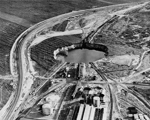
On the morning of October 21, 1974 at about 8:00 a.m. it was observed that the surface was subsiding in an area south of the salt plant. As subsidence continued, railroad tracks crossing the site were left suspended in midair. By noon the growing basin-like crater had a diameter of about 200 feet, and had filled with ground water as shown in the photograph, Figure 10. Settlement continued until the afternoon of October 23, 1974 when the crater stabilized at a diameter of about 300 feet, with walls in the soil and alluvium nearly vertical. Water surface in the crater was 21.5 feet below ground level. Water depth was later determined to be 37.5 feet at the deepest level. The volume of the crater was calculated to be 90,000 cubic yards. Figure 11, photographed by the Wichita Eagle and Beacon, November 12, 1974, shows the stabilized sinkhole site after the railroad tracks had been relocated.
Figure 8--Interpretive map showing the Cargill salt plant, subsidence areas, sinkhole, "Airlift Field," and brine wells in the NW of Section 19, Township 23 South, Range 5 West.
Area affected
The 1974 sinkhole developed within a portion of the plant yards and brine well field of the Cargill salt processing plant near the southeast city limits of Hutchinson, Kansas, in the NW of Section 19, Township 23 South, Range 5 West, Reno County, Kansas. Within the area of the crater were two railroad sidings which serve the plant, the main line of the Missouri-Pacific Railroad, and probably one or more abandoned salt wells as shown on the map (Fig. 9). The exact location of many of the abandoned salt wells is uncertain or unknown. Figure 9 was prepared by the author utilizing a surveyed base map on which were plotted the approximate location of abandoned salt wells from surviving well records, often vague or ambiguous. Records exist for 72 brine wells numbered consecutively in order by date of drilling. Abandoned Wells 1 and 2, located in the area now occupied by the present plant buildings, are known to have been in use as late as 1906. No records exist for many of the still earlier salt wells operated by the former Barton Salt Company, beginning in 1892.
Figure 9--Base map, W2 of Sec. 19, T. 23 S., R. 5 W., Hutchinson, Kansas.
Much difficulty was experienced in constructing time map showing well locations (Fig. 9). In addition to the lack of records, a base map showing well locations furnished to Cargill at the time of purchase of the properties in 1972 was found to be incorrectly plotted. The base map was drawn assuring a standard size land section. It was determined that Section 19 is an irregular short section with the correction being made in the W2 of Section 19, as shown in Figure 9, with the result that the W2 NW on which the plant, the sinkhole, and time abandoned wells in question are located measured 1275.40 feet (not 1320 feet) along its north line, 1281.02 feet (not 1320 feet) along its south line, but is nearly normal along its east line, 2645.13 feet (not 2640 feet). By using an erroneous base map for plotting well locations, it was thought that Well 9 might be located within the crater, but during a visit on November 21, 1975, the author found the casing of an abandoned salt well in the nearly vertical south wall of the pit where it had become exposed by slumping of the crater walls in the 13-month interval since the collapse. Its location fits the word description of Well 9 (drilled in 1914 and plugged November 17, 1928) "located in the southwest corner of the intersection of (the projection of) Osborne Street and Missouri-Pacific tracks." Word descriptions for other abandoned wells do not provide mappable locations. For example, Well 5 mapped by the author in Figure 9 as within the crater is described only as "located between Park and Osborne Streets between the Missouri-Pacific tracks." There is no visible evidence for the existence of Well 5 either within the crater or adjacent to it. Well 5 was drilled in 1908, and required one month's work to plug in July 1929 as follows:
Plug set at 415 feet, filled with brick to 395 feet, mud to 320 feet, and stone to 295 feet. Bailed hole dry and filled with concrete to top.
Figure 10--Photograph by the Hutchinson News, October 21, 1974. Diameter of the sinkhole after 14 hours is about 200 feet. View toward the north, with the Cargill salt processing plant in the background. Note the tree on the east (right) bank. Dark circle around perimiter is a temporary fence being erected to restrain spectators.
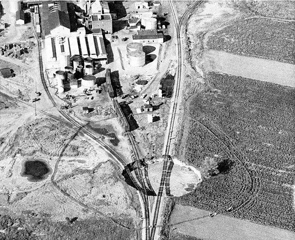
Figure 11--Photograph by the Wichita Eagle and Beacon, November 12, 1974. Diameter of the stabilized sinkhole is 300 feet. View toward the south, with the Cargill salt processing plant in the foreground. Note that the tree mentioned in Figure 10 now stands in 18 feet of water within the crater near the east (left) bank. Missouri-Pacific railroad tracks have been relocated around the sinkhole.
Sources of information
Much of the data pertinent to understanding of the sinkhole, and how and why it occurred when and where it did, consists of subsurface information, chemical analyses, flow pressures, etc., available through informed personnel such as plant employees of Cargill, geologists and engineers associated with the State of Kansas Department of Health and Environment, railroad personnel, or through the author's own observations. The author visited and photographed the site on various dates in 1974 and 1975, witnessed the drilling operations within the crater in November 1975, and has had the cooperation of the executives and staff of Cargill. This portion of the report makes extensive use of the unpublished investigation by Ralph E. O'Connor, Area Geologist, prepared for internal use by the State of Kansas Department of Health and Environment in March 1975, and released for this use. The present report makes extensive use of data from these sources.
Cargill personnel reported that at the time the settlement was first observed there was a rolling motion associated with the water contained within the sinkhole. Nearby wells being operated by the airlift method were shut down; thereafter, the rolling motion in the sinkhole quieted. Communication is thus indicated between the water-filled crater and wells in the "Airlift Field." Samples of the water in the sinkhole, taken October 22, 1974 during active sinkhole collapse, had a chloride content of 89,000 parts per million (ppm). Salt saturation is 226,000 ppm or 311,300 milligrams per liter (mg/l). Two weeks later, on December 5, 1974, the chloride content within the crater was 1,525 ppm. This indicates that a slug of diluted brine was displaced into the sinkhole at the time of active collapse, but substantially dissipated within two weeks.
Airlift Field
Because of the free migration of dissolving fluids in the wells, the actual outline of a mature salt well gallery cannot be precisely defined. The hypothetical outline depicted in Figure 8 includes the operating wells, excludes others, and is thus the approximate outline as well as can be defined. At the time the crater started to form, Wells 34, 61, and 62 were being run as a gallery with Well 35. The term "gallery" is used to indicate that these wells are part of a group of wells known to be hydraulically connected, presumably in a common salt cavity. Locations of these wells are shown in Figure 8. Wells 34, 61, and 62 are spaced on 300-foot centers on a line bearing northeastward, the projection of which intersects the crater. Well 62 is 125 feet from the abandoned well exposed in the bank of the crater, thought to be Well 9. Wells 34, 61, and 62 were being used for access to the salt cavity for disposal of waste solids from the plant. These waste solids were being transported in waste brines which are reported to vary widely in chloride content from saturated to 22,500 ppm as measured at the time of cratering. The waste brine stream was being injected at pressures varying from zero (vacuum or gravity flow) to 150 psi at the time of collapse. Well 62, the disposal well closest to the crater, was equipped with 705 feet of 2-inch tubing in July 1970, of which 26 joints, or about 550 feet, of the 2-inch tubing were recovered when it and Wells 34, 35, and 61 were abandoned in November 1974. These waste-bearing brines carried solid wastes (precipitates of calcium sulfate, magnesium chloride, and other minerals) in amounts approximating three-fourths ton per day. The solids settle in the salt cavity during slow flow through the gallery. Upper flow water from which the solids had settled by gravity was withdrawn through Well 35 (300 feet northwest of Well 62) by the airlift method, hence the term "Airlift Field."
Airlift is a system of producing fluids from a well wherein a small tube is injected part way down the well and air introduced under sufficient pressure to escape beneath the end of the tube and rise in the well fluid. The rising air lightens the fluid column sufficiently to cause the well to flow in an erupting fashion. Well 35 was equipped with 17 joints, or about 357 feet, of one inch tubing down which compressed air was forced to accomplish the airlift. Although injection of solid waste-bearing brines were being made only into Wells 62, 61, and 34, most of the abandoned salt wells near the collapse area are known to be connected in the subsurface with this gallery. For example, fresh water was formerly put in Well 13 for the purpose of dissolving the salt with return brine to be taken out of Well 9, a distance of 800 feet. By study of the records of well histories showing interconnections of wells, the author has indicated on the interpretative map, Figure 8, the approximate extent of this gallery. Well 9, on the south bank of the collapse area and connected to the airlift gallery, served as an individual brine production well for ten years from 1914 to 1924, after which it was used as a brine production well for a gallery including other injection wells in addition to Well 13 on the south edge of the property.
It should be noted that the injection of weak disposal brine in one well in a gallery does not affirm that saturated brine produced elsewhere is derived from the disposal brine. In the case of a gallery which is not pressure tight, fresh water can be induced through unsealed casings or through leakage around the outside of uncemented casings. In either case, the introduced water dissolves additional salt resulting in cavity extension by enlarging the gallery an indeterminate area. It is reported that Well 13, a water injection well connected with brine production Well 16, "blew up," meaning the pressure of the injected fresh water broke the mud seal on the outside of the uncemented four-inch casing set at 355 feet. This occurred in 1931 at which time the well was plugged. A similar incident occurred in Well 16, the connected brine production well, in which uncemented four-inch casing had been set at 345 feet with a seed bag packer and mud. Swelling of the seeds, commonly flax seed, plus the weight of the mud provided the only seal. In 1931 it too blew out the mud seal around the casing and was patched by repacking around the top of the four-inch casing with hemp to stop the leak. These examples give some idea of the conditions within the airlift gallery (approximate limits, gallery outline Fig. 8) adjacent to and connected with the sinkhole at the Cargill plant.
Early indication of subsidence
In retrospect, probably the most conspicuous advance indications of the 1974 subsidence at the Cargill site were the adjacent flat areas in which water collected located immediately west of the sinkhole and another to the north between the railroad tracks. These areas are visible in the color photograph on the front cover, in Figure 10, and are mapped in Figure 8. Other advance indications are the reports by railroad maintenance personnel that the switch at the south edge of the crater was frequently difficult to throw because of being out of alignment and periodically required realignment. The track was required to be raised at intervals for two years prior to the collapse. The crater affected no buildings, and there are no paved roads; hence no preliminary advance indication in the form of cracks could be observed. The sandy hummocky ground in the plant yard will not preserve and show ground cracks.
Also in retrospect, the general area of the sinkhole could probably be considered to be subsidence prone because of continuous production of salt from the well group in this area for 84 years since 1892, including its recent utilization for plant waste brine recycle and disposal. A poorly drained low area east of the salt plant within the curve of the railroad tracks is faintly visible on the air photograph, Figure 10, upper right, and mapped in Figure 8 by shading. This also appears suspect as a salt-related subsidence area. This site is immediately adjacent to the present salt processing plant under which are the locations of brine supply Wells 1 and 2, in use in 1906, as shown on the interpretative map, Figure 8. The locations of other early brine supply wells utilized in the period from 1892 to 1912 are now unknown. Because the removal of each ton of salt creates a cavity of about 15 cubic feet, or 1/2 cubic yard, it can be estimated that the cavity created in these first 20 years of operation near Wells 1 and 2 is approximately 150,000 cubic yards, or approximately one and one-half times the measured surface volume of the 1974 sinkhole south of the plant.
A third area of prior subsidence is briefly described [above] as the June 1952 subsidence area at the then Barton Salt Company plant. It involves the northwest corner of the present main plant building, the driveway, and an area west of the railroad tracks as mapped in Figure 8. Subsidence here is definitely salt related, and was still active in 1974 as shown by the westward tilt of the cement floor and the closure difficulties experienced with the large sliding doors of the truck loading dock. Together, these three areas of prior surface subsidence adjacent to the old Barton Salt Company plant affirm that the salt in the vicinity has been extensively removed by solution mining.
Historical background--Cargill plant
When rock salt was discovered at Hutchinson in 1887 (Cowan, 1940), it was speculated that the city would develop into one of the largest salt manufacturing cities in the west. In 1890 there were 23 Kansas plants producing salt (Taft, 1946, p. 265), but the financial panic of 1893 put many of the new plants out of business. When Cow Creek, which flows into the Arkansas River at Hutchinson, flooded the countryside in 1894, many others were forced to shut down. By 1900 there were only eight plants producing salt in Kansas (Taft, 1946). The salt brine wells used in these short-lived operations were commonly abandoned and left without any plugging and with no known surviving well records.
The Barton Salt Company, now Cargill, Inc., is the oldest of the three presently operating companies active in the Hutchinson area. The Barton Salt Company was founded in 1892, and began operating with three open grainer pans. Its original capacity was rated at about 40 tons of salt per day. In 1913, the Barton Salt Company passed to new owners, C. H. Humphrey and E. T. Guyman. C. H. Humphrey, an experienced chemist, took over active direction of the company and began a broad sweeping modernization and expansion program that was to literally remake the original company. He installed vacuum pans, rotary vacuum filter wheels and dryers, new grainer pans, complete packaging equipment, and new salt block presses. Cargill succeeded the Barton Salt Company in 1972 and continued its operations making changes and improvements, but essentially continuing the salt production practices of the Barton Salt Company.
The Cargill plant produces salt by evaporation of brine. Because of the nature of the manufacture of salt by evaporation, these operations are required to be carried out on a continuous 24-hour basis. The brine is produced by dissolving of the salt deposit by the introduction of water through wells drilled for this purpose. Brine is produced when the feed water contacts and dissolves the salt; the resulting brine is produced from the same well by an annular tubing/casing arrangement, or from a nearby well when their cavities have coalesced to form a gallery. Water input wells are known as feed wells--brine is produced by pressure (forcing) in the case of pressure-tight cavities, or by pumping using airlift or well pumps--in more mature systems which have ceased to be pressure-tight.
Water for supplying the brine wells is derived from three water supply wells completed in the alluvial sands and gravels, and also from the plant cooling tower, with total water use at an average rate of 250 to 300 gallons per minute.
A typical brine well employs 150 to 170 feet of surface casing which is cemented in place, and producing casing which is set at approximately 480 feet; tubing is run inside the production casing to the base of the salt section which averages 770 feet in depth. In the pressure or forcing system, water is pumped down the tubing under sufficient pressure to force the resulting brine up the annular space between the tubing and the production casing. The brine then flows to surface collecting tanks. In the case where cavities of wells have dissolved together ("coalesced"), or have ceased to be pressure-tight, it becomes necessary to use either airlift or one of several types of well pumps.
Because of the free dissolving nature of this process, the extent of the solution cavities was largely unknown other than those encountered in drilling or by reported coalescences. Modern well logging and cavity survey techniques had not been developed. Cavities often merged with one another by free dissolving, and no particular stress was put upon attempts to prevent cavity coalescence. New wells were started at a rate averaging one every two to two and one-half years. Salt saturation of the produced brine was nominally 100 percent.
Figure 9 depicts the approximate locations of the earlier wells for which records exist. The reader will recall that, as mentioned above, well operations date back over 80 years--in early days no records were kept; wells were abandoned or "lost." Modern casing, cementing, and abandonment techniques have only recently become employed. From the position of the subsidence basin and sinkhole crater, as shown on Figure 8, it will be seen that the crater location is related to the old brine wells of the Airlift Field, being sited among the wells. Not shown on either Figure 8 or 9 are 27 other active brine supply wells supplying most of the brine to the plant in 1974. These wells are located as much as one mile south of the plant in an area along the Arkansas River, under Carey Park and the Hutchinson municipal zoo. All but four of the brine wells mapped in Figure 9, in operation close to the plant in 1974, have since been plugged and abandoned, and replaced with a new supply field about one-half mile southeast of the plant, Wells 1-H to 8-H, Figure 9. Average salt production was approximately 500 tons a day in October 1974, but at that time the plant was in the process of extensive remodeling to expand its daily capacity to about 750 tons of salt per day.
Post-subsidence Activities and Investigations
Cargill, Inc.
When the ground collapse was observed on Monday morning, October 21, 1974, an emergency fence was erected and guards were retained to restrain curious spectators who had seen and heard the news and television coverage of the developing sinkhole. Freight cars were moved from the edge of the pit. The use of Wells 34, 35, 61, and 62 in the Airlift Field was immediately discontinued. Later, tubing was pulled from all four wells and efforts were made to log the wells before abandonment. Because no buildings and no principal brine or fresh water lines were involved in the growing sinkhole, plant operations were not interrupted by the settlement. Subsequently, a new eight-well brine field has been developed 2,000 feet southeast of the plant in the E2 SW of Section 19. In the new field, wells on 400-foot spacing arc operated as four fresh water input wells each connected by fracturing to one of the four brine production wells, making four pairs of wells. These new wells are designated 1-H to 8-H, Figure 9.
Missouri-Pacific Railroad
At the time of the settlement, immediate steps were taken by the Missouri-Pacific Railroad to relocate its main line tracks which were intercepted by the crater. On October 23, while subsidence was still active, work was underway for the railroad bypass, mapped in Figure 9, just east of the sinkhole. In order to verify the competence of this route, three test holes were drilled. Two holes, drilled to 250-foot depth by Darling Drilling Company of Hutchinson, encountered shale bedrock at a normal depth of 68 feet. A third hole, designated on Figure 9 as "RR 2," was drilled by the Engineering Testing Company of Wichita, Kansas, to 519 feet total depth in salt without encountering cavernous conditions. The top of the salt, expected near 400 feet, was not determined because the hole was neither cored nor logged with wire line logs. At the request of the Missouri-Pacific Railroad, the hole was used by Wichita Testing Laboratories for a limited refraction seismic survey program employing 12 geophones. Two sets of fan shots were recorded by detonating explosives at depths of 506 and 425 feet in RR 2 hole. The 12 geophones were spaced in two arcs equal distant from the shot point. If all substrata traversed are uniform in depth and thickness, the travel time through the rocks to each geophone will be the same. By this method, any significant abnormal condition such as a subsurface void between shot point and geophones will be recorded by a difference in time delay to the geophones affected. The fan spread toward the north and east from RR 2 recorded such delay in an arc including the shaded subsidence area east of the plant in Figure 8, inferring cavernous void space due to salt dissolution. The second fan spread toward the west from RR 2 gave a similar indication through the area of the sinkhole and the Airlift Field, Figure 8, but of more significance to the railroad, indicated normal travel times in the area east of Wells 10, 11, and 12, confirming the absence of cavernous conditions and verified the feasibility of construction of the new railroad tracks. The very limited emergency refraction seismic program was discontinued after the two fan spreads. The specific location of the railroad bypass was made on the basis of tolerable curvatures.
State of Kansas Department of Health and Environment
While the crater was still actively forming, Melville W. Gray, Director of Environment, State of Kansas Department of Health and Environment, was present at the location and immediately organized an investigation directed to determine the environmental impact of the formation of the crater. The investigation included a drilling program for ground-water monitoring to which he assigned Ralph E. O'Connor, Area Geologist, whose written interim report of March 17, 1975 records basic factual data. Water samples were collected October 24-25, 1974, just after active cratering ceased, from 39 water wells in the vicinity, and were analyzed for chlorides, showing an average of 367 mg/l chlorides. Twelve observation water wells were drilled by the State of Kansas Department of Health and Environment to permit sampling of ground water in the area. Average depth of the wells was 65 feet; shale bedrock was encountered near 60 feet. Complete analyses of water samples from these wells, taken in November 1974, about one month after the sinkhole collapse, showed results which varied widely from 3,130 mg/l to 90,300 mg/l total solids and 488 mg/l to 52,000 mg/l chlorides. The depth to the water surface within the sinkhole was measured as 21.5 feet below average ground level. Water depths within the sinkhole were measured and ranged from 18 feet to 33 feet. Monitoring of groundwater quality in the 12 holes drilled for that purpose is continuing. No chloride contamination other than that initially present had been detected to February 1976; the State of Kansas Department of health and Environment continues its surveillance of well plugging, drilling of new wells, and the management of plant waste waters.
Solution Mining Research Institute, Inc. Investigation
Because unplanned subsidence is a major hazard of the solution mining industry, a considerable portion of the research effort of the Solution Mining Research Institute (SMRI) is directed toward an understanding of the mechanism and establishment of the time framework of ground subsidence resulting from salt mining by dissolution. Accordingly, SMRI requested permission of Cargill, one of the corporate members of the Institute, to conduct a test drilling program adjacent to and within the sinkhole. In November 1975, one year after the ground collapse, SMRI engaged Wichita Testing Laboratories (WTL) to drill ten holes, two on opposite banks of the 300-foot diameter sinkhole and eight from a barge on the pond within the sinkhole. Location of the test holes is mapped in Figure 12. A geological cross section through eight of the holes is presented in Figure 13. Both figures are from the WTL report.
Figure 12--Test location plot, sinkhole, Cargill Salt property, Hutchinson, Kansas.
Figure 13--Geological cross section, sinkhole, Cargill property, Hutchinson, Kansas. Vertical exageration x 2. Prepared by Wichita Testing Laboratories for the Solution Mining Research Institute, November, 1975. "Shale" is bedrock. For location see Figure 12.
Holes B-1 and B-2 outside the sinkhole were drilled using a truck-mounted Mobil B-40 drilling rig, equipped with 7-inch diameter continuous flight auger. Borings within the sinkhole were made with a smaller raft-mounted drilling rig, equipped with 70 feet of 4-inch diameter continuous flight auger. The nearly flat surface of the bedrock, reddish-brown Permian shale, was reached by seven of the wells at depths near 70 feet in holes B-1 and B-2, or near 50 feet for barge-drilled holes. The water surface, elevation 1502.5 feet, is 21 feet below the average ground level. Three holes near the center of the pond in the deepest water failed to encounter shale bedrock at total depth of 70 feet (the limit of drilling equipment on the barge). This infers the presence of a restricted area of bedrock collapse, approximately coinciding with the 30-foot water depth contour of Figure 12 which defines an elliptical area with axes of 130 and 90 feet, or an average diameter of 110 feet, as compared to the 300-foot average diameter of the nearly circular sink.
| Borehole | Water Depth | Shale Depth |
|---|---|---|
| B-1 | ||
| B-2 | ||
| B-3 | 3 | 5 |
| B-4 | 37 | * |
| B-5 | 25 | 45 |
| B-6 | 27 | 47 |
| B-7 | 30 | 46 |
| B-8 | 36 | * |
| B-9 | 34 | 59 |
| B-10 | 37 | * |
| *Not reached at 70' maximum depth. | ||
The results of this drilling indicate (1) that the surface sinkhole is developed in loose sand and gravel, (2) that only 20 percent of the material removed from the sinkhole was in a position to move directly downward, and (3) that 80 percent of the material removed required some lateral component in order to move down the hole in the bedrock. This is interpreted as evidence for extensive "piping" of an aqueous sand-gravel slurry down a restricted opening into the void space created by dissolution of salt formerly present from 400 to 750 feet. Estimates and calculations are as follows:
| 1. Volume of sinkhole, estimated | ||
| Above water level | 50,000 cubic yards | |
| Below water level | 40,000 cubic yards | |
| Total | 90,000 cubic yards | |
| 2. Volume of central area of sinkhole bounded by 30-foot water depth contour, Fig. 8 | ||
| Above water level | 7,000 cubic yards | |
| Below water level | 11,000 cubic yards | |
| Total | 18,000 cubic yards | |
| 3. Ratio of volumes | 18,000 | |
| 90,000 = .20 = 20% | ||
These volume figures were calculated from the average ground surface to the bottom of the water, as mapped in Figure 12, but not to the top of the sand. The interval labeled "silty sand (muck)" consisted of water saturated fine sediment which could be penetrated by pushing the drill through it. In contrast, the sand required drilling, and the firm bedrock, the Permian shale, was so resistant that it could be penetrated only a foot or so with this type of equipment.
In addition to the sinkhole drilling project, SMRI cooperated with Cargill in coring and wire logging the salt section in one of the new brine wells being drilled in the SW of Section 19, and contributed to preparation of a descriptive log of the salt cores under the direction of Dr. A. J. Hendron, University of Illinois, consultant to SMRI on rock mechanics and salt cavity design.
Cause, Mechanism, and Time Framework: 1974 Sinkhole
Cause
It appears at this time that the 1974 sinkhole was the result of the removal of salt in a cavity configuration which exceeded the span capabilities of the overlying rock layers. This, in turn, caused roof rock failure which progressed by sequential collapse of the overlying rock layers until the uppermost bedrock ledge was breached, permitting 90,000 cubic yards of sand and gravel to move down the bedrock opening. In developing this explanation, Donald S. Robinson, plant manager (personal communication), thinks it possible that brine pumped from Well 35 in the Airlift Field gallery exceeded the amount of recycle brine returned to the gallery, thus permitting induction of makeup fluid (fresh water) through leaks from improperly plugged, or entirely unplugged, abandoned brine wells for which insufficient records, or no records, exist. The resulting movement of fresh water was downward from the shallow aquifer by way of the abandoned brine wells which provided connections with the water-saturated overburden. Lateral movement of fresh water or unsaturated brine through the gallery at the roof dissolved additional salt causing cavity enlargement over a large area by removing critical roof support resulting in broad areal subsidence or downwarping prior to sinkhole formation.
It is recognized that many factors combined to cause the surface subsidence at the Cargill plant, and must be given consideration. Salt had been produced at this location for a long time, from perhaps as early as 1888 until October 1974, by the method of uncontrolled dissolution in the Airlift Field gallery. Underground conditions are unknown, and largely unknowable, due to the abandonment of many former brine wells often with no surviving well records. Moreover, production in this area is at relatively shallow depths, from 400 to 750 feet, with structurally weak Permian shales and siltstones overlying the salt. Also, all production takes place under a shallow and prolific fresh water aquifer in unconsolidated sand and gravel. It is recognized as a causative factor that the operation of brine pumps in the Airlift Field gallery for all the years of salt production and of waste brine recycling provided the needed energy input into the system. The surface sinkhole is located within the brine production gallery limits and directly under the main line of the Missouri-Pacific railroad tracks. Periodic ground vibration with the passage of long freight trains may be a contributing cause in the localization of the surface sinkhole. Although the exact combination of factors contributing to cause the sinkhole formation in October 1974 at the Cargill plant is unknown, it is recognized that the most visible phase of sinkhole development--when 90,000 cubic yards of loose sand and gravel moved downward in three days time leaving a crater 300 feet in diameter--was not itself the cause of land subsidence but was, rather, the end result of a sequence of events originating with gallery operation.
Mechanism and time factors
In view of the factors outlined above, knowledge of the time frame and mechanism involved ultimately in collapse of the land surface remains to be developed. It is not known, for example, whether the crater is situated above a narrow vertical chimney-shaped bedrock void localized in a small area by contributing factors such as the presence of an unknown old brine well, or the daily vibrations from passing freight trains. If so, then the mechanism involved can be interpreted as chimneying, as described by Landes and Piper (1972), and the implications are that solid roof rock, perhaps in its full original thickness, remains over the rest of the mined area of the Airlift Field gallery, and that the 90,000 cubic yards of sand and gravel was transported downward and deposited at depths below 400 feet within void space from which salt had been dissolved. This could be tested by a suitable drilling program. An alternative interpretation is that the circular sinkhole is located above a wide cone of underground roof collapse over the Airlift Field gallery with only relatively thin undisturbed bedrock remaining in place over a large area. In this case, the bedrock collapse can be attributed to stopping and the relatively small opening through which sand and gravel moved downward might be localized at the apex of the broad cone of roof rock failure. This, too, could be investigated by a drilling program. If correct, test holes should encounter the transported sand and gravel at shallow depths, perhaps 150 to 250 feet, and should find roof-fall shale material at depths below 400 feet filling former void space from which salt was dissolved.
Other investigations which might contribute knowledge of the mechanism involved include extensive recording of wire line geophysical logs in any future holes drilled, additional seismic refraction work, diamond coring of both bedrock and collapse breccia, and fluid injection, or withdrawal, tests. Fortunately, it is well recognized that when the energy input into the system ceases (in this case, when the brine pumps are shut off), then cavity enlargement ceases, subsidence terminates except for minor compaction, and sinkhole areas tend to stabilize. Beyond that, little else is established concerning the actual mechanism of ground subsidence due to salt dissolution and the time frame involved. Research investigations under actual field conditions are much needed.
Kanopolis, Kansas: Land Subsidence Due to Cratering of Salt Mine Shaft
Subsidence sequence
In 1949, the shaft of the abandoned Crystal Salt Mine at Kanopolis, Ellsworth County, Kansas, was plugged and filled to the surface with rock and dirt. Twenty-three years later, on January 12, 1972, W. Holms, plant superintendent of the Acme Brick Company, then owners of the property, was surprised to find the formerly filled shaft open and empty. He lowered a brick on a long rope to a depth of 700 feet indicating only 90 feet of rubble fill in the shaft at that time. The abandoned shaft was constructed in 1923, with dimensions 17 feet by 9 feet by 790 feet deep, and hence had an original volume of 4,500 cubic yards. Figure 14 depicts cross sections through the upper shaft on various dates. Profile "A" indicates conditions on January 11, 1972. Note the presence of unconsolidated Quaternary water sands ("W") near 35 feet, and the presence of Cretaceous sandstones near 80 and 140 feet. Profile "B," March 6, 1972, and Profile "C," March 8, 1972, show how the surface around the mine shaft cratered, forming a steep-sided pit having a final volume approximately four times the volume of the mine shaft. The cratering of the surface was relatively rapid. The first two days were witnessed by N. W. Biegler (personal communication) of the State of Kansas Department of Health and Environment.
Figure 14--Shaft profiles, abandoned Crystal Salt Mine, Ellsworth County, Kansas. Sandstones are stippled, shales are patterened; "W," water. Measurements are in feet.
Surface subsidence began at the Crystal Mine shaft on the morning of March 7, 1972. By that afternoon, Biegler estimated that the dimensions of the cone shaped hole were about 40 feet north-south and 30 feet east-west, indicating the dropping into the shaft of a volume of about 150 cubic yards of unconsolidated soil, sand, and shale (assuming the cone-shaped hole was then 25 feet deep). Twenty-four hours later at 3:00 p.m., March 8, 1972, Biegler measured the cone shaped opening as 65 feet by 40 feet, Figure 14, Profile "C." At a depth of 31 feet, the opening narrowed to about 25 feet north-south and about 15 feet east-west due to a ledge of Cretaceous Dakota sandstone below the unconsolidated Quaternary Grand Island Formation. It is calculated that another 666 cubic yards of each material had dropped down the shaft. The shaft was then partially filled and blocked at the bottom by the 90 feet of fill, measured on January 12, plus the material dropped in forming Profile "C." Evidence of blocking is provided by the fact that the formerly dry shaft had filled with water to a depth of 110 feet below the surface on March 8. No other measurements were recorded until several days after the cave-in had stabilized. When surveyed on March 28, 1972, by Brady and Wilson of the Kansas State Geological Survey (Frank Wilson, personal communication, October 29, 1974), the steep-sided pit measured 129 feet by 95 feet. Water level was 23.3 feet below the surface. The depression was flat bottomed at an average depth of 60 feet below ground level as determined by 28 soundings. The position of the former shaft could not be ascertained, presumably because it was filled and plugged with slump material. Measurements from the soundings are diagrammed as the stabilized Profile "D," Figure 14. Brady and Wilson estimated that it would require about 20,000 cubic yards to fill the pit level with the ground. This is more than four times the volume of the original shaft. About 95 percent of the material from the crater moved down the shaft after March 8, and in so doing, moved into a water-filled shaft which was partially filled and blocked with rock debris prior to the settlement of the great bulk of the material. These observations and calculations provide the basis for speculation as to how a rapidly forming cave-in could move a volume of sand, shale, and rock debris several times the original shaft volume down that same water-filled shaft, leaving it plugged to within 60 feet of the top.
Mine history; Crystal Salt Mine
The crater formed in the abandoned shaft of the Crystal Salt Company mine located at the east edge of the city of Kanopolis, in Section 25, Township 15 South, Range 8 West, Ellsworth County, Kansas. The mine was a room and pillar mine, ceiling 9 feet for the most part, with a maximum ceiling of 11 feet, and with a salt removal ratio of 70 percent. It connected underground with the adjacent Royal Mine. In 1941, the Crystal Mine was sold to the Morton Salt Company, who operated it until 1947 when operations were terminated because sloughing of shale between 200 and 300 feet depth caused alignment of the cribbing in the shaft to shift sufficiently to affect the operation of the hoisting equipment. It was reported in 1949, when the shaft was plugged, "that a large concrete block lodged at 126 feet below the surface and the shaft was filled to the surface." (N. W. Biegler, personal communication, April 12, 1972). It is possible that the timbers supporting the concrete plug at 126 feet gave way causing the concrete block to fall through air to the bottom of the shaft in November 1971, at which time residents of Kanopolis reported feeling a sonic boom. Later, the remainder of the 126 feet of fill fell to the bottom of the shaft, leaving it open and air-filled as discovered by W. Holms on January 12, 1972.
No direct observations could be made concerning conditions in the lower shaft of the abandoned Crystal Salt Mine during and preceding the sequence of events depicted in Figure 14. Such information is available, however, from another abandoned salt mine, the Little River Salt Mine in Rice County, which is discussed next because of the applicability of the information as part of the explanation for rapid land subsidence at the Crystal Salt Mine shaft.
Information, shaft and mine deterioration, Little River Salt Mine shaft
Data accumulated in 1963, and confirmed in 1975, in connection with the sealing of the shaft of the abandoned Little River Salt Mine in the NE NE of Section 18, Township 19 South, Range 6 West, Rice County, Kansas, provide information as to shaft and mine deterioration. Active mining of salt in this 400-acre room and pillar underground salt mine ceased in 1926. The mine was kept open until 1938, then abandoned with the shaft left open and unsealed. Depth to the mine floor was 796 feet at the shaft, the mine ceiling was 11 feet high, and 75 percent of the salt was mined, leaving 25 percent as pillars. The shaft, which originally measured 7 feet by 17 feet (Jewett, 1956), deteriorated due to fresh water seepage for 25 years until 1963. Figure 15 depicts the position of the top of the rubble pile, and the foot-by-foot volume of the shaft as determined by a sonar survey from which the shaft cross-section diagram was constructed. N. W. Biegler (personal communication, April 25, 1975) reported that 12 years later, in 1975, when new owners conducted an investigation as to the feasibility of using the mine for propane storage, it was confirmed that the shaft was not hydraulically tight.
Figure 15--Lower shaft, sbandoned Little River Salt Mine, Rice County, Kansas. Constructed from a sonar survey to the top of the rubble at 750 feet. Dashed lines indicate position of shaft as constructed. Measurements are in feet.
In the course of further investigation, one hole was drilled down the center of the filled shaft to 655 feet. Two additional holes were drilled through the bedrock adjacent to the shaft. Both of these holes drilled out of bedrock into areas of shaft enlargement near 540 to 560 feet, confirming the accuracy of the sonar survey. Note that considerable shaft enlargement occurred in shales immediately above the salt. These shales, present at depths from 540 to 560 feet, are dark gray to black with vertical joints filled with red halite. The shales were deposited in equilibrium conditions with the halite crack filling, and are quite unstable in the presence of fresh water or air. The rubble is built up about 50 feet above the original mine floor. Note also the extensive mine roof collapse and the extensive bedding-controlled collapse of salt near 740 feet, or about 60 feet above the original mine floor. The mine shaft was sealed by grouting in 1975, and the mine is being operated as LPG storage for propane, using bottom hole pumps set in large diameter drilled shafts for product removal.
Volumetric data, Little River Mine
It is noteworthy that the extensive void space developed by roof collapse and salt dissolution in the 25-foot interval from 725 feet to the top of the rubble at 750 feet was measured by sonar as a volume of 13,100 cubic yards, or four times the volume of the original shaft to 750 feet (3,305 cubic yards). The calculated average diameter for the 25 feet from 725 feet to 750 feet is 134 feet. The volume of salt which was originally mined from an underlying area 134 feet in diameter with an 11-foot ceiling, was only one-third as much as the sonar measured void space from 725 to 750 feet, indicating considerable dissolution of salt in place or by fresh water falling on the collapsed rubble pile.
Application to the Crystal Mine, Kanopolis, Ellsworth County
This volumetric information concerning shaft bottom conditions in the Little River Salt Mine is considered to have application to the Crystal Salt Mine in Ellsworth County. Rubble from the surface subsidence crater at the Crystal Mine in the amount of four times the original shaft volume may have filled a collapsed lower shaft area rather than being displaced into the low ceiling abandoned mine through two narrow portals. In conclusion, the Crystal Mine shaft cave-in crater is another example associated with the removal of salt in which land subsidence occurred rapidly (in a few days) because of the presence of a near surface aquifer in unconsolidated sand and gravel.
Prev Page--Salt Deposits of Kansas || Next Page--Oil and Gas Operations
Kansas Geological Survey, Geology
Placed on web July 24, 2009; originally published February 1978.
Comments to webadmin@kgs.ku.edu
The URL for this page is http://www.kgs.ku.edu/Publications/Bulletins/214/04_land.html