![]()
Prev Page--Discharge || Next Page--Chemical Character
Ground Water, continued
Ground-water Areas
Generalized ground-water areas and subareas within the County are shown on Figure 20 and are explained in the section of the report that follows. There are four major ground-water areas: the Arkansas Valley, the Ninnescah Valley, the Wellington Upland, and the Ninnescah-Wellington Upland. Where ground-water conditions are not uniform within an area, it has been divided into subareas.
Figure 20—Map of Sedgwick County, Kansas, showing generalized ground-water areas and subareas.
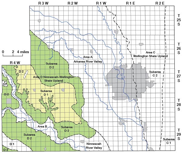
Arkansas Valley (Area A)
The Arkansas Valley is characterized by its extreme flatness and the poorly developed surface drainage of the land flanking the Arkansas River. The area is underlain by alluvial sediments of Pliocene to Recent age that are the most productive water-bearing rocks in the County. Although the deposits are stratified and lenticular (Pl. 2)., the sand and gravel beds containing most of the ground water are interconnected, and the complete sequence of silt, clay, sand, and gravel beds responds to long-term withdrawals of water as a singe aquifer.
The Arkansas River valley contains most of the usable ground water in the County, and most of the large ground-water supplies are obtained from this area. The quantity of ground water in storage within the sediments of the valley is about 6.1 million acre-feet if an assumed specific yield of 20 percent for the sediments is correct. This volume of water does not represent the amount that could ultimately be withdrawn from the area, but rather a reserve that could be regulated to provide a perennial yield without progressive depletion of storage if other hydrologic factors affecting the aquifer are known. Ultimately, the perennial field will depend on the average annual recharge. Williams and Lohman (1949, p. 129) estimated the net average recharge in the Arkansas Valley to be about 20 percent of the annual precipitation or about 320 acre-feet per square mile per year in years of normal precipitation. Experience has shown this recharge rate to be approximately correct for the Wichita well-field area of Harvey County (Stramel, 1956). However, this figure does not take into account the concurrent natural discharge by seepage into streams and evapotranspiration, and if these losses from the ground-water reservoir could be salvaged for use, the effective recharge rate would be much greater. In much of the Arkansas Valley adjacent to the principal streams the depth to water below the land surface is less than 10 feet (Pl. 1) and discharge by evapotranspiration in this area is thought to exceed all other forms of natural discharge. In much of the remaining area of the valley the water table is deeper but is in clayey silt or other fine-grained sediments underlying the surface, and the capillary rise of water in these sediments may bring a large volume of water close enough to the surface for evapotranspiration to become an effective means of discharge. No studies of this phenomenon have been made in the area, but random observations of soil moisture conditions and crop growth strongly suggest that the capillary fringe above the water table may contribute significantly to ground-water discharge. Much of the natural discharge of ground water in the Arkansas Valley could be salvaged by pumping strategically spaced wells to lower the water table below the level where evapotranspiration is effective and to intercept ground water that is now discharged to streams. Maximum utilization of the ground-water supply by this method, while feasible, might cause some water quality problems owing to movement of poor quality water from the Arkansas River and social and economic problems in regard to established water rights and agricultural practices.
The yields of wells in the Arkansas Valley range from a few gallons per minute for small domestic and livestock wells to about 1,500 gpm for large municipal and industrial wells. In favorable areas, well yields of 2,500 gpm should be possible without excessive draw down. The yield of individual wells designed and developed for maximum yield is dependent on several geologic and hydrologic factors. Maximum well yields will be obtained generally where the saturated thickness, sand and gravel thickness, and transmissibility of the sediments are greatest. These properties of the sediments in the Arkansas Valley are shown by means of contours on Figures 21 to 23. The saturated thickness map was prepared by superimposing the water-table contour map (Pl. 1) over the bedrock contour map (Pl. 3) and drawing contours through points of equal saturated thickness. The sand thickness contour map was prepared by contouring points of equal sand thickness obtained from logs of wells and test holes and does not include silt and clay beds that were present at the well site. The transmissibility map was prepared by applying permeability values obtained from selected pumping tests in the area to the sand and gravel thickness as recorded in the logs of wells and test holes for those formations for which samples were available. In much of Arkansas Valley, particularly where the total sand and gravel thickness is greatest, the permeability of these sediments decreases with depth. The permeability value applied to an individual sand and gravel bed at a well or test-hole site was based on a comparison of the lithology of the bed with that of similar sediments from wells where permeability data derived from pumping tests were available.
Figure 21—Map of Sedgwick County, Kansas, showing the saturated thickness of the unconsolidated Neogene sediments in the Arkansas Valley.
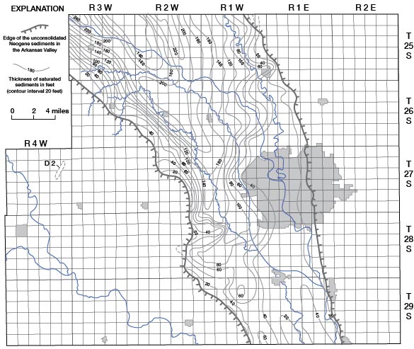
Figure 22—Map of Sedgwick County, Kansas, showing the total thickness of sand and gravel in the unconsolidated Neogene sediments in the Arkansas Valley.
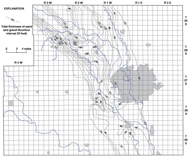
Figure 23—Map of Sedgwick County, Kansas, showing the estimated transmissibility of the unconsolidated Neogene sediments in the Arkansas Valley.
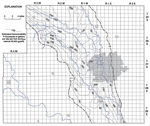
The preparation of maps such as those shown on Figures 21, 22, and 23 require the exercise of some personal judgment in interpretation of available data, and the maps should be used with this thought in mind. However, the data presented on these maps are sufficiently accurate to provide a useful guide in selecting areas for water-supply developments. Although local geology at a well site and the well construction method will strongly influence the yield obtained, an estimate of the well yield can be made from the transmissibility map. Where the transmissibility is less than 50,000 gpd (gallons per day) per foot, water adequate for farm use and for lawn or garden irrigation is readily obtained. Where transmissibility is between 50,000 and 150,000 gpd per foot, well yields of 500 to 1,000 gpm can be expected, and where transmissibility is over 150,000 gpd per foot, yields of over 1,000 gpm are commonly available. The saturated thickness and sand thickness at a well site will affect the long-term yield of a well and should be considered when estimating well yields. In parts of Arkansas Valley, particularly along the sides, the transmissibility is relatively high but the aquifer is thin, and lowering the water level near a well more than a few feet by pumping will reduce the transmissibility and thus the well yield.
Ninnescah Valley (Area B)
The Ninnescah Valley area as shown on Figure 20 includes the lowlands flanking the Ninnescah River and its principal tributaries, the North and South Fork Ninnescah rivers. The area is underlain by silt, sand, and gravel that locally yields up to 250 gpm to properly constructed wells. The deposits underlying the valley range in thickness from a featheredge along the margin to about 55 feet, but average about 45 feet. The depth to water below land surface in the valley ranges from less than 10 feet adjacent to the rivers to as much as 25 feet along the valley sides.
The lithology of the sediments underling the valley is quite heterogeneous, and generalizations regarding favorable sites for ground-water developments cannot be made from the data available. Locally the complete section may be composed of silt, and a short distance away sand and fine gravel may predominate. Where the river channel is cut into sand and gravel beds, wells close to the channel could produce moderately large yields by induced infiltration of river water. However, the location of favorable sites for such wells would require exploratory drilling, and wells would need protection from periodic flooding by the river.
Few details are known regarding recharge and discharge of ground water in the Ninnescah Valley. However, the Ninnescah River is effluent throughout its course in the County. The river is flanked by a dense growth of large trees and brush throughout most of its course, and during part of the year ground-water discharge by evapotranspiration probably exceeds discharge to the stream.
Wellington Upland (Area C)
The Wellington Upland area includes all of the uplands east of the Arkansas Valley. Low, rolling hills are typical geomorphic features. Thin loess mantles the divides between the many small creeks draining the area, and the Wellington Formation is exposed on most of the slopes bordering the creeks. The eastern two-thirds of the area is within the Walnut River drainage basin.
The area has been divided into two subareas on the basis of the occurrence of ground water, and the subareas are shown on Figure 20 as the Gypsum Subarea (C1) and the Loess-shale Subarea (C2). The line dividing the two subareas is arbitrarily placed at about the point where the type of well ordinarily used indicates the source of the ground water supplying the well.
Within Subarea C1, drilled wells less than 150 feet deep obtain water from solution openings in gypsum and anhydrite beds in the lower part of the Wellington Formation. The water is commonly under artesian pressure but flows at the surface in only a few places. Several creeks in the subarea have cut into or near the water-bearing, zone, and large springs and seeps provide a perennial flow in the creeks. The water-bearing, gypsum beds dip to the west and may underlie Subarea C2, but within this subarea the water from the gypsum beds is believed to be too salty for use. Wells yielding as much as 350 gpm have been drilled in Subarea Cl, but the water is too highly mineralized for many uses without dilution with better quality water. However, where no other source is available, the water is used for domestic and stock wells.
Subarea C2 is the most difficult area in the County in which to obtain a ground-water supply, and wells yielding more than a few gallons per minute were not observed. Water supplies for domestic and stock use are obtained generally from large-diameter dug wells less than 40 feet deep that provide storage volume for the small quantity of water moving through the rocks. The water is thought to occur in small solution openings and crevices in the weathered upper part of the Wellington Formation. Thin loess deposits cover much of the subarea and although the loess has a low permeability, it may be more permeable than the underlying shale, and, therefore, retard the rate of surface run-off, allowing some recharge. Wells within this subarea are subject to failure during prolonged drought periods.
Ninnescah-Wellington Upland (Area D)
The Ninnescah-Wellington Upland includes all of the County west of the Arkansas Valley except that occupied by the Ninnescah River valley. This area includes the broad slopes flanking the Arkansas and Ninnescah valleys and the relatively flat, undissected inter stream divide between the two valleys. The surface of most of the Ninnescah-Wellington Upland is underlain by loess, which overlies sand and gravel in part of the area. The bedrock surface is the Wellington Formation in about the eastern one-third and the Ninnescah Shale in the western two-thirds.
The area has been divided into two subareas on the basis of the occurrence of ground water. The two subareas are shown on Figure 20 as the Loess-sand Subarea (D1) and the Loess-shale Subarea (D2). Subarea D1 is largely confined to the uplands but does include the small abandoned valley in the southwest corner of the County where ground-water conditions are similar. Within Subarea D1 the surface material is loess that ranges in thickness from a featheredge to about 40 feet. The loess is underlain by deposits of sand and gravel containing some silt. These deposits attain a maximum thickness of about 35 feet. The sand and gravel beds are best developed in the area between and south of the towns of Goddard and Garden Plain and thin to zero near the edge of the area. Well yields of as much as 50 gpm can be developed where the sand and gravel beds are thickest, but during prolonged periods of drought the yields probably would decrease sharply. Where the sand and gravel thins, well yields become less, and near the edge of the area the sand and gravel may be completely dry.
The occurrence of ground water, within Subarea D2 is not uniform; in general well yields are small, but adequate for farm and domestic use. The land surface within the subarea slopes toward the major streams and is underlain in part by loess and some colluvium and locally by only a soil over bedrock. The northeastern part of the subarea flanking the Arkansas Valley is underlain by loess that locally attains a thickness of about 75 feet and contains sandy zones near the base. The lower part of the loess is saturated, and wells penetrating sandy zones obtain adequate water for domestic and stock use. In those parts of Subarea D2 flanking the Ninnescah Valley, the loess and colluvium are thin, and the water table is commonly in bedrock. Wells penetrating the Ninnescah Shale are usually less than 100 feet in depth, and the water is believed to occur in crevices, solution openings, and bedding planes within the weathered part of the formation. Well yields from the Ninnescah Shale generally are larger than from the Wellington Formation and may range from 1 gpm to as much as 75 gpm depending on the number of openings penetrated by the well. The well yield that might be expected at a particular location cannot be predicted, but a supply adequate for domestic and stock use can be developed in most of the subarea.
Prev Page--Discharge || Next Page--Chemical Character
Kansas Geological Survey, Geology
Placed on web Nov. 1998; originally published Dec. 1965.
Comments to webadmin@kgs.ku.edu
The URL for this page is URL=http://www.kgs.ku.edu/General/Geology/Sedgwick/gw06.html