![]()
Prev Page--Stratigraphy || Next Page--Chemical Properties
Systems of Mining Employed in Kansas Coal Fields
There are three systems of mining generally employed in the coal fields of the state, namely: The Long Wall system, the Room and Pillar system, and the Strip Pit system. The greater part of the coal mined in Kansas is by the room and pillar system, although the long wall system is employed in the larger part, in areal extent, of the coal fields. In Cherokee and Crawford counties the room and pillar system is employed for all underground mining, and also to a limited extent in the vicinity of Pleasanton. Elsewhere the long wall system is exclusively employed.
The system employed at any particular locality is chosen with reference to its greater adaptability to local conditions. The long wall system is employed in coal beds which are comparatively thin, as from 18 to 30 inches, and where the roof is rather weak, soft or brittle; yet this system is often operated where the roof is good and firm, but is seldom put in use where there is a dip of over three degrees. The room and pillar system is employed in coal beds ranging from 3 feet and upwards in thickness. In mining coal of this thickness the waste material would not be sufficient to "pack wall" the roof and a large amount of rock or wooden props would have to be brought into the mine for use as roof supports. For the room and pillar system the roof should be of good material and very firm. The strip pit method of mining is one adopted in all coal fields where the coal stratum comes to the surface and is operated at or near the line of outcrop. It. is thus found in operation side by side with the long wall and room and pillar systems.
The Long Wall System
The Long Wall system of coal mining is employed principally in the coal fields of Leavenworth and Osage counties, at which localities the system has been studied extensively by the writer. In connection with a study of the following descriptions frequent references to the accompanying drawing is advised. As the name would imply, the face of the coal, that is that part that is exposed to view in the mines by the mining operations, is in the form of a long wall, producing an approximately circular or elliptical figure around the shaft as a center.
The principal advantage of the long wall system over other systems is the ease with which the waste material, obtained in working the coal, is disposed of, it being employed to help sustain the roof. The most essential condition is that there be a sufficient amount of waste to furnish ample material for the "packed wall" or "gob. "Timber" cribs" or props are used in connection with the "gob," and in those localities where the coal cannot be removed without considerable loosening of the roof and floor the number of props must be doubled or trebled.
There are two general methods employed in the long wall system, namely: the long wall system by retreating or withdrawing, and the long wall system by advancing.
In the former method gangways or entries are driven to the outer limit of the mine and the coal is then worked back. In this method the main hauling ways and air passages are open to the boundaries of the proposed mine. The real mining operations then begin and continue shaftward until all the coal within the prescribed boundaries has been removed. The method of mining by retreating is practically not employed in this state.
In the latter method, long wall mining by advancing, the coal is removed in approximately concentric rings, the shaft being the center. The mine thus is developed as the coal mining operations proceed, permanent roadways and air passages being opened as the face of the coal is advanced. In this system the coal is wholly removed, the "packed walls" or the walls made from the loose material obtained in removing the coal, are placed to help support the roof, and the passage ways, entries, etc., are walled up and brushed or dressed down to allow room for mules and cars to pass. Plate XXXIV and Figure 38. This development of the mine continues until the face has retreated to such a distance from the shaft that the hauling of the coal is more expensive than the sinking of a new shaft, or until the limit of the property has been reached.
Figure 38—Plan of State Mine at Lansing, showing the Progress of the Mining Operations up to the Year 1897. Long Wall System of Mining.
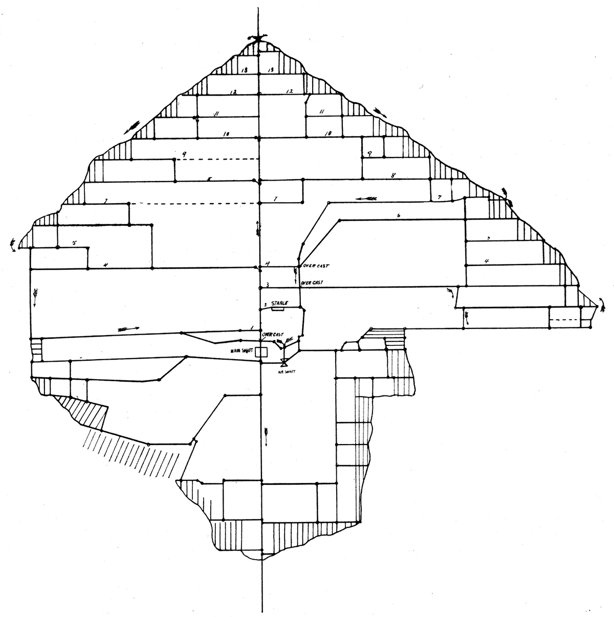
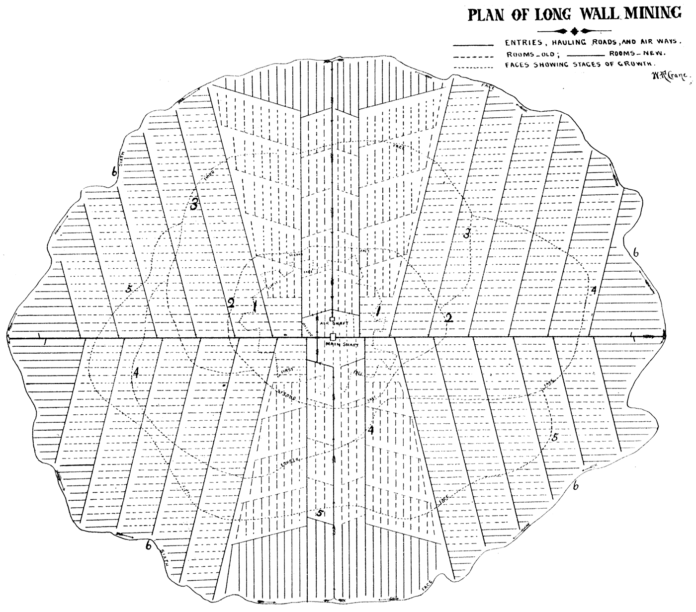
Plate XXXIV—Plan of long wall system of mining.
Heavy solid lines represent entries, hauling roads, and air passages; light solid lines and broken lines represent new and old rooms; numbered dotted lines represent faces of coal at different stages of the growth of mine. Arrows represent direction of air currents and show method of ventilation. This plate represents the system of long wall mining by advancing, that is, the coal is removed, wholly, as the face of the coal advances.
These methods are modified by local conditions of the roof, such as a weak and rather brittle, or strong and flexible, or elastic roof. The advancing method is employed in the Kansas coal fields under almost all conditions of roof.
Long Wall Mining by Advancing
The shaft is sunk until the stratum of coal is passed through. A hole called the "sump," from 8 to 12 feet in depth, is formed below the coal as an extension of the shaft proper, and is intended as a drainage reservoir for the water of the mine.
Two main entries or gangways are then driven horizontally through the coal, intersecting each other at the shaft at right angles. These entries are usually driven in a general north and south, and east and west direction. Along the main entry on both walls the coal is worked, the "packed walls" being built up as the face of the coal advances. On the walls of the main entry at about a hundred feet from the shaft and at intervals of a hundred feet, side entries are driven. The first two on each side are at right angles with the main entry while those farther away angle away from the entry at an angle of from 110 to 115 degrees.
The coal is generally worked in the side entries running east and west, the north and south entries being used for the hauling ways and air passages. This order may of course be reversed, making the east and west entries the main hauling ways while the coal is removed from the north and south entries. Along the side entries at intervals of forty to forty-five feet, passage ways, as nearly as possible at tight angles with the main entry, are walled up to prevent the roof from sinking, and are also "brushed" down, that is the roof strata are removed for several feet above the coal and in the form of an arch, thus making room for the general travel of miners and mules.
There are really no rooms in the long wall system of mining, although the space of forty odd feet between the two passage ways on the side entry are generally designated as such. In a mine where the coal has been removed uniformly in all directions from the shaft the rooms are so located that a miner working in one room can see the lights of the miners working in the two adjacent rooms on the right and left. The face of the coal is in the form of a long wall extending entirely around the shaft. Plate XXXIV.
It will be noticed that on the east and west entries there are places where the width of the room increases as the face of the coal advances, thus necessitating the gradual enlargement of several rooms or the addition of more rooms. The character of the roof and floor are the factors which generally govern the choice in these matters. If the roof is good and firm the rooms are generally enlarged, even to the employment of two men in one room, but when the roof is weak and brittle the addition of more rooms is preferable.
After the face of the coal has advanced—Plate XXXIV—to a considerable distance from the shaft, cross driveways connecting the entries along which the coal is worked are placed at intervals of from a hundred to two hundred feet apart and are also walled up and" brushed" down, as they are to be used as hauling ways, etc. The coal is then worked from the crossways in a manner similar to that employed in the side entries. Thus the face of the coal is advanced in the neighborhood of two hundred feet, when a new crossway driven at right angles to the rooms worked forms the basis of a new set of rooms, which also extend two hundred feet and are then cut off by new crossways and new rooms started, and so on.
Method of Wall Packing and Pillar Making
The methods of wall-packing or "gobbing " vary considerably according to the varying conditions of roof and floor. The miner is expected to keep the roof well supported in the particular room in which he works. As a general rule he receives no extra pay for so doing, but in case props are used for support they are furnished by the mine operators. When the roof is fairly strong and firm, the larger pieces of the waste are built into walls at intervals of from six to ten feet apart, the distance between these walls varying with the strength of the roof and the amount of material available for such purposes. The waste material is banked up between the walls, thus forming the "packed wall" or "gob." Plate XXXV. In those mines where the roof is rather weak props are almost always employed. In some cases the props are put in permanently, no attempt being made to remove them as the face of the coal advances; they being surrounded and covered up by the "gob," while elsewhere they are used simply for temporary support and are removed and advanced with the face of the coal, thus saving the expense of new props. Only occasionally is one broken in removing, or, in still rarer cases, by the pressure of the superincumbent strata. When the props are removed the weight of the roof is ultimately borne by the "packed wall" which is often compressed from a thickness of 24 inches to a solid layer only 4 inches in thickness. Plate XXXV.
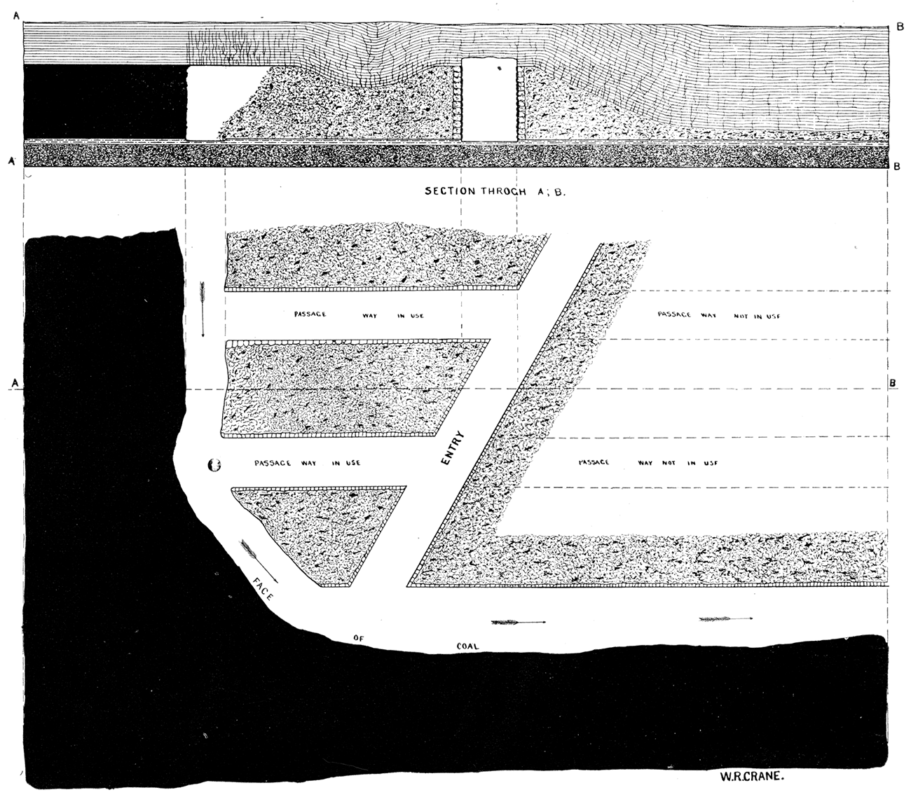
Plate XXXV—Vertical section and horizontal plan of long wall system of mining.
The black represents the coal; the cross-hatched, worked-out portions of mine; open spaces, entries and air passages; and the arrows represent air currents. In the vertical section, the entry is seen open in the middle of section; the opening for mining operations and air passage is seen next to face of coal at the left-hand side. The gob or wall-packing is also shown in the vertical as well as horizontal section and plan.
The entries must also be walled up as the packing wall advances. The wall on each side of the entry is built by the miner operating the room opening on that entry. The miner seldom receives extra pay for this work, but in most cases he prefers to build the entry wall if he can mine near the hauling way, rather than have no wall to build and yet haul his coal by hand fifty to a hundred feet to an entry.
Method of Mining Coal
The problem before the miner is how to remove the coal from its position between two hard strata, the roof and floor, with as little waste and breakage as possible. The particular condition of the coal stratum with accompanying strata are the essential elements which govern the method employed. When the coal is underlaid with fire clay it is undermined by removing the clay to a depth of 18 to 24 inches and forward from under the coal to two or three feet, thus leaving a portion of the coal stratum projecting into the cleared space, where the miner works, without any support except the tensile strength of the coal itself. This projecting mass of coal in course of time falls, partly from its own weight and partly from a slightly downward movement of the superincumbent strata. By driving a wedge between the roof and the upper surface of coal it may be soon forced down. Portions of coal, the full thickness of the stratum, three feet wide and from sixteen to twenty feet in length, are often forced down by a few strokes upon a well directed wedge.
Where the floor is too hard to be removed by the ordinary methods, the cutting is done in the lower portion of the coal stratum. It would be preferable in such case if the roof was not too hard to do the cutting in the roof, prying, blasting, or even wedging up the coal. No coal would be wasted, at least, if such a method were adopted, the waste being the objection to cutting into the coal itself. Machine cutters are used quite successfully when the underlying stratum is fire clay. Mining machines are used at Leavenworth and Atchison and also in the southern coal fields of the state in similar operations under the room and pillar system. It has been noticed that when the coal is removed up even with the clay underlying the coal, and allowed to stand in this way for some hours, the outer six inches of the clay becomes excessively hard, making the cutting out exceedingly difficult. This is obviated by leaving a portion of the coal stratum projecting into the working space, which acts similarly to a bracket, distributing the pressure exerted from above more evenly throughout the coal and underlying strata.
Method of Opening Entries or Driveways
As the long wall system of mining is employed only in comparatively thin beds the necessity of making the hight of the entries considerably greater than the thickness of the coal stratum in order that men and mules may travel along it is quite evident. Plate XXXV. When the roof material is very hard and the expense of cutting or blasting down is too great, the channel is cut downwards into the floor. This method is employed only where the roof is very hard. When the roof material is soft enough to work by either cutting or blasting the entry is raised to its proper hight by "brushing" down the roof.
The single entries are about five feet wide at the base and four feet at the top, and average five and a half to six feet in hight. In the Osage City mines the hight of the entries is seldom over four feet and they are correspondingly narrow-from four to four and a half feet. Occasionally the entries are made five feet high and six feet wide. A width of twelve feet is almost always given for double entries. In most mines where all of the hauling as well as mining is done by hand the hight is seldom above four feet.
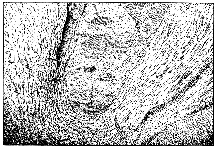
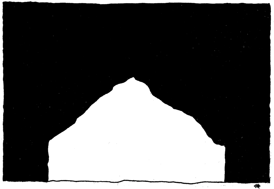
Figure 39—A Vertical Section and Horizontal Plan of a "Choke-out." in the Roof of Entry, as seen in Mine at Weir City. This is due to percolating waters loosening the roof, which keeps falling, each succeeding lamina breaking off short of the preceding, thus forming a natural arch.
However, as the roof material constantly exposed to the damp air of the mine rapidly disintegrates and as it softens and loosens will fall, the hight of an entry is thus gradually increased. In places where the pressure of the overlying strata, partially relieved by the removal of the coal, has produced fissures in the roof the percolating waters flow into the mine, loosening the roof material until it falls. This caving-in continues until it finally "chokes itself out," that is forms a natural arch. Figures 39 and 40. By this natural process continually in progress the entries are becoming constantly higher. Another phenomenon noted in the mines, compensating for this hightening process, is the gradual elevation of the floor, known as "creeping." The floor material gradually rises in the entries, yielding to the unbalanced pressure resulting from the opening of the entry. The rapidity of the "creeping" varies with the character of the floor, and is most rapid with clay floors in damp mines.
Figure 40—A "Choke-out" in Roof of Entry.
Method of Hauling
The coal is hauled from the face of the coal to the shaft in cars. The capacity of the car is from 4,000 to 10,000 pounds. In all of the better equipped mines the iron T track is used, but in those mines operated wholly by hand, wooden tracks made from narrow strips of plank or board are employed. The track is laid from the shaft to the face of the coal in the main entries or hauling ways. Leading from the main tracks are branch tracks following the side entries and cross entries to the face of the coal. It will be noticed on entering a mine, conducted on the long wall system, that the tracks are in many cases curved inward toward the shaft. This is due to the advancing of the face of the coal, the transfer place not being changed very often, seldom more than once a week. In some mines, cars are run along the face of the coal which is loaded directly into them, while in other cases the coal is hauled to the entry in wooden carriages and in still other instances the coal is "buggied" out. The "buggy" is a wooden platform about two and one-half by three and one-half feet, with two somewhat semicircular runners, so constructed that it may be dragged in either direction without turning around. The coal is placed upon the "buggy" and dragged to the entry and is there loaded into the car. When the regulation cars are used they are run in on tracks extending from the entry into the room about half way. The branch tracks are connected with the main track at the entry by iron plates which allow adjustment. The inner ends of room tracks are not connected but are left free so that they may be advanced with the face of the coal. In case the cars are run along the face of the coal a "pusher" is commonly employed. The duty of the "pusher" is to keep empty cars ready for the miner to fill, and to remove the loaded cars to the entry where they are transferred to the main track. Empty cars are brought in to replace the loaded ones but, until needed, are removed from the track to allow the passage of the loaded cars. The miners sometimes look after their own cars, loading them and placing them upon the main track, where they are taken in charge by the general hauling crew.
Cost of Mining Operations
As nearly as can be ascertained the cost of driving an entry is on the average $4.50 to $5 per yard. The average cost of "brushing" down the shale of the roof in the entries is from $1.25 to $1.75 per yard. The cost of removing the coal, or the amount that the miner receives for mining, is from 3 to 5 cents per bushel, 75 cents to $1.25 per net ton; but occasionally only 2 1/2 cents is paid per bushel, 62 cents per ton. These are figures for lump coal; for mine run coal the pay is lower still, ranging from 25 to 40 cents per ton.
The Room and Pillar System
The Room and Pillar system of mining is employed in those localities where the coal strata are comparatively thick, ranging from 3 feet upward. Figure 41 and Plates XXXVI and XXXVII. There are two special reasons why the room and pillar system is employed in the thicker coal beds:
Figure 41—Face of Coal, Room and Pillar System.
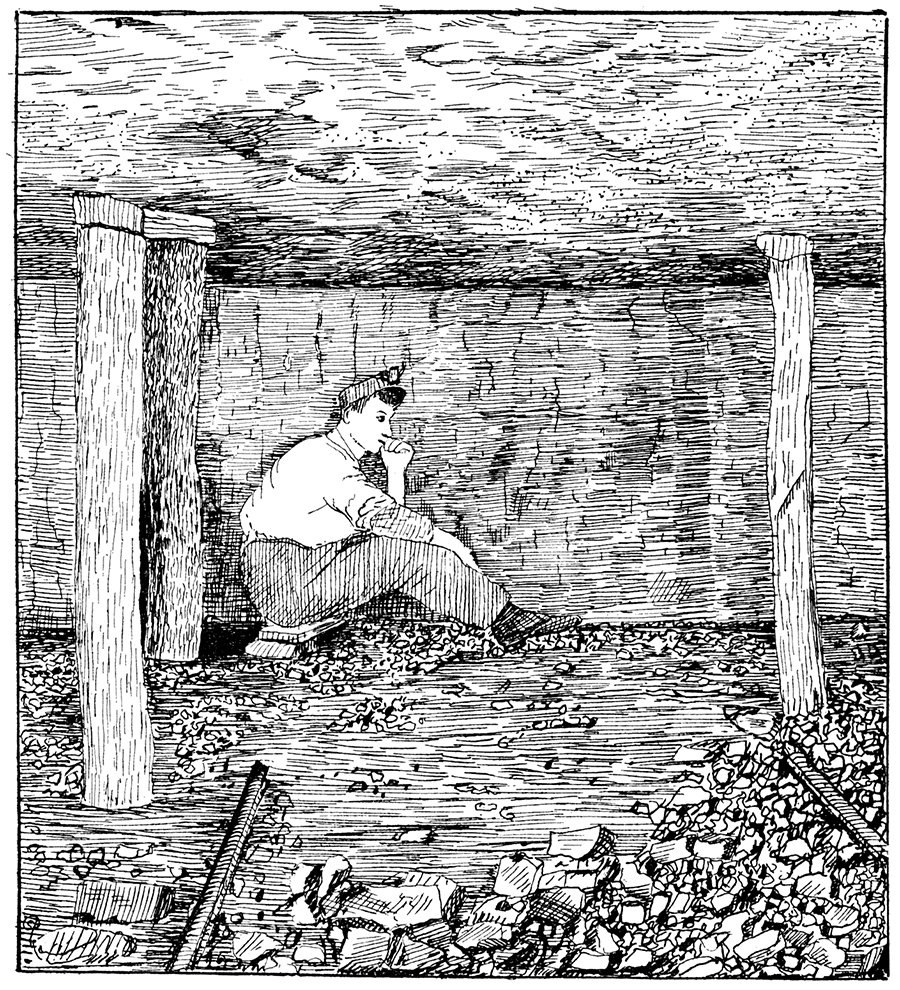
Plate XXXVI—Double entry method-room and pillar system.
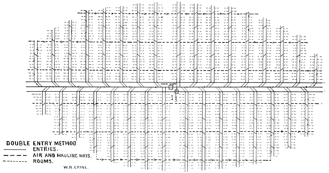
Plate XXXVII—Plan of single entry method, room and pillar system, showing system of mine ventilation.
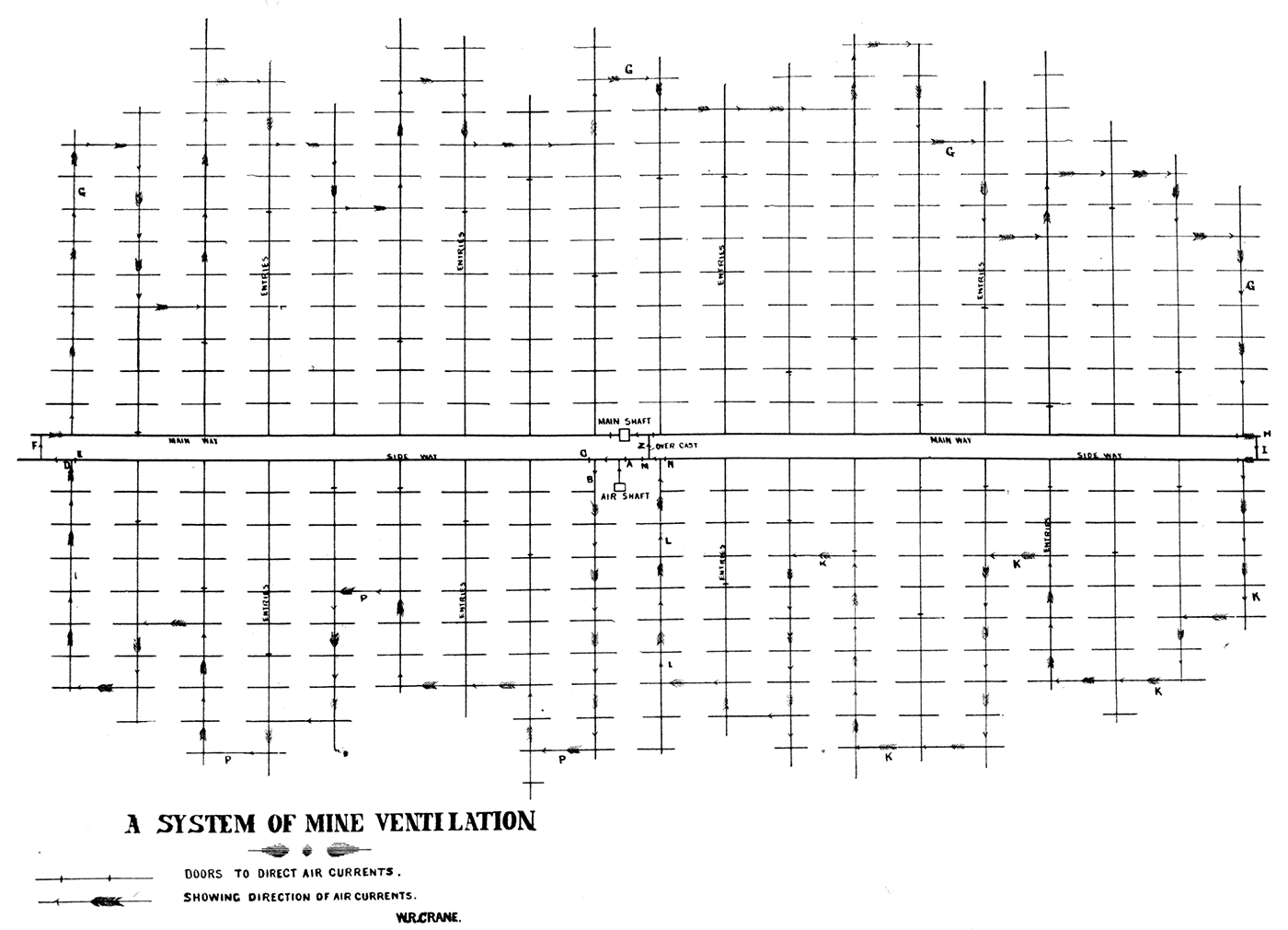
The heavy line passing through main shaft is the main entry or way, the heavy line parallel to it represents the side way. Perpendicular to these entries are side entries, used for hauling roads and air passages. On each side and perpendicular to these side entries are rooms, represented by the cross lines. The arrows show the direction of the air currents and, taken together, show the system of ventilation.
First, a large amount of coal is removed, leaving a large vacant space, and with a comparatively small amount of waste. It has been found less expensive and far more practical in thick coal beds to leave a column of coal standing every few feet, as a natural support to the roof, than to remove it and then introduce material from outside at additional expense.
Second, it so happens that in Kansas the thick coal beds capable of being worked by the room and pillar system lie in a territory where the clay veins, horsebacks, faults, etc., are so abundant.
There are two methods generally employed in the Room and Pillar system, namely: the Double Entry and Single Entry methods. The double entry is probably the best and is used most extensively.
Double Entry Method
The shaft is sunk and the" sump" formed as in the long wall system. On the floor of the coal and extending in each direction an entry is driven. The entry is known as the main entry and is the axis of the system around which all the other parts are grouped. It is twelve feet wide and five feet high. On each side of the main entry at a distance of about forty-two feet a side entry or way is driven parallel with the main entry. These entries or ways on each side extend even with the ends of the main entry, all three of them being advanced as the coal is exhausted and the mine developed.
The spaces between the main entry and the side entries are used as pillars. On the walls of the side entry, opposite the main entry and pillar, and at intervals of approximately 100 feet, two entries thirty-two feet apart and parallel are driven at right angles with the side entries. These entries extend in straight lines as far as the coal is worked, Cross ways connect them, not at right angles, but making an angle of about sixty degrees. These oblique roadways are located about a hundred feet apart. Between two sets of the double entries, cross entries parallel to the side entries are driven connecting the two inner entries of the double sets. These cross entries are used for hauling and also for air ways and are driven every forty or fifty feet along the double entries.
Along the sides of the double entries opposite the pillars rooms are opened. The rooms are thirty-five feet from center to center, of which twenty-four feet is worked, thus leaving twelve feet for a pillar between the rooms. The rooms are worked 200 feet long.
The side and main entries are connected by double hauling roads, which are extensions of the double entries extending perpendicular to the side entries, but as there are two side entries there are twice as many entries opening on to the main entry as on to the side entries. The double hauling roads connect the main and side entries at an angle of about forty-five degrees, thus throwing the entrances on the main entry end of the double hauling road several feet in advance of the entrances on the side entry end of the road. To simplify matters and not have too many roads opening into the main entry at the same point, although on opposite sides, the double entries on one of the side entries are set forward one-half the distance between two sets of double entries, thus making the openings of the roadways into the main shaft alternate one side with the other. The hauling roads opening on to the main entry angle toward the shaft.
By a careful study of the figures in connection with the above explanation this method can be readily understood.
Single Entry Method
In the single entry method there is only one main entry, with no side or secondary entry or entries associated with it. Plate XXXVII. In this method the main entry is generally advanced with the development of the mine, but sometimes is extended at the start to the proposed limits. From both sides of the main entry other entries are driven at right angles. These entries are located along the main entry at regular intervals of a hundred feet, those on one side being advanced or set back about twenty feet, From the sides of the single entries rooms are driven as explained under the double entry method. The cross entries, air passages, etc., are almost identical with the double entry method. The essential differences are that the main entry is without side entries and the single entries connect directly with the main entry and not with the side entries as in the double entry method.
Single and Double Entry Methods Combined
A combination of the double and single entry methods has some of the advantages of both. Plate XXXVIII. The details of the method are as follows:
In this system only one main entry extends through the mine, with which are connected on each side the double entries and roadways. Along the main entry, on both sides of the shaft, entries are driven twelve feet wide and five feet high which extend into the coal bed at right angles to the main entry. These side entries are generally about fifty feet from the shaft and are located at regular intervals of a hundred feet along and on both sides of the main entry. The entries on one side of the main entry are set back as seen in Plate XXXVIII, so that there will be plenty of room to connect the side entry track with the main entry track, thus eliminating the possibility of collisions between two trains entering upon the main track entry at the same time. Parallel with the main entry, and from twelve to fourteen feet on each side, other cross entries are driven connecting the side entries, which are at right angles with the main entry. About twenty-five feet from the main entry (on the side entry) a roadway is driven, extending away from the shaft, making an angle of about sixty degrees, This roadway cuts into another side entry which runs parallel with the first mentioned entry and is used in part as an air and hauling way. These two side entries extend side by side through the mine from the main entry, gradually advancing as the mine opens up. The space between these two entries is left as a pillar to support the roof and is from twelve to sixteen feet wide.
On the side of the entry opposite the main entry, rooms are driven thirty-six feet apart, the coal being taken twenty-seven feet wide. Plate XXXIX. The two series of rooms driven from the two entries and in diametrically opposite directions into the same area of coal will ultimately open into each other. A space of from seven to twelve feet is left between the rooms as a pillar. The waste material obtained in the mining operations is used to close up the worked out rooms so as to prevent any alteration in the system of ventilation, which would certainly result if passages were continually opened and not closed. The main, side, and cross entries are used as air passages and hauling ways as the conditions of the mine require.
If an understanding of the arrangement of the various entries and passages and the relation existing between them is obtained for a small portion of the mine, the complete arrangement with the relation of the parts to the whole will very readily be seen on examining Plate XXXVIII.
The location of the air shaft, overcasts, and the general details of the system of ventilation employed in the different systems of mining will be discussed under a separate head.
Methods of Mining in the Room and Pillar System
Methods of Driving Roadways
The methods employed in driving entries or roadways do not differ essentially from those in the long wall system. The coal stratum being thicker will not require as much work either in lifting or digging up the floor or in "brushing" down the roof as in the long wall system. The hight required beyond the thickness of the coal is generally attained by removing the loose strata but when, as is occasionally the case, the roof is excessively hard, the fire clay underlying the coal is lifted. The roof being trimmed in the form of an arch is self supporting. The entry is about six feet high and varies from six to twelve and fourteen feet in width.
Figure 42—Horizontal Plan, showing Method of Opening Entry by "Cutting."
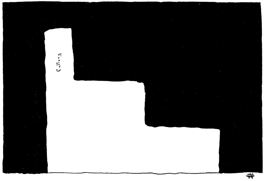
Figure 43—Horizontal Plan, showing Method of Opening Entry by "Cutting."
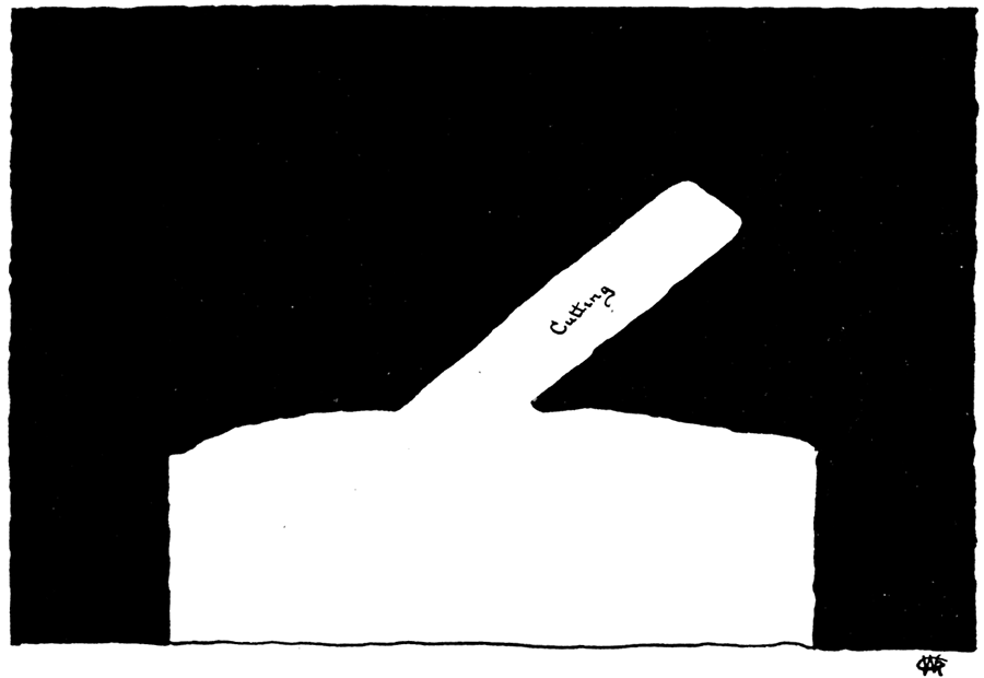
The entry work consists principally in cutting through the coal, "brushing" down the roof, or lifting the floor, and laying the track. The coal is removed from the entry by a system of cutting similar to the method employed in removing the coal in the room. The direction which the miner wishes to take being known, he begins cutting through the coal on one side of the proposed entry. A space is cut the thickness of the coal, about two feet wide and three feet into the coal., This space is called a "cutting." Figures 42, 43, 44, and 45. The length of time required in making a "cutting" depends upon the character of the coal and whether there are any "horsebacks" intersecting the coal stratum. To make a good clean "cutting" generally takes a day. A drill hole is then made at the other side of the proposed entry. A charge of powder introduced into the drill hole will, when fired, find room to loosen the coal lying between the drill hole and cutting, and thus by a successive repetition of cutting and blasting the entry is advanced. When a "horseback" crosses the proposed line of entry it must be cut through or passed around. The miner is paid $1.50 per foot for cutting through "horsebacks." If the angle made by the crossing of a "horseback" and an entry is very small the direction of the entry is changed so that it will pass along side of the "horseback," thus utilizing the "horseback" as a pillar. It will therefore be seen that if a large number of "horsebacks" are met with in the development of a mine, the cost of development, on straight lines, will be rather high; on the other hand if the entries are made to conform with the direction of the "horsebacks" a very irregular, unsymmetrical mine will be the result.
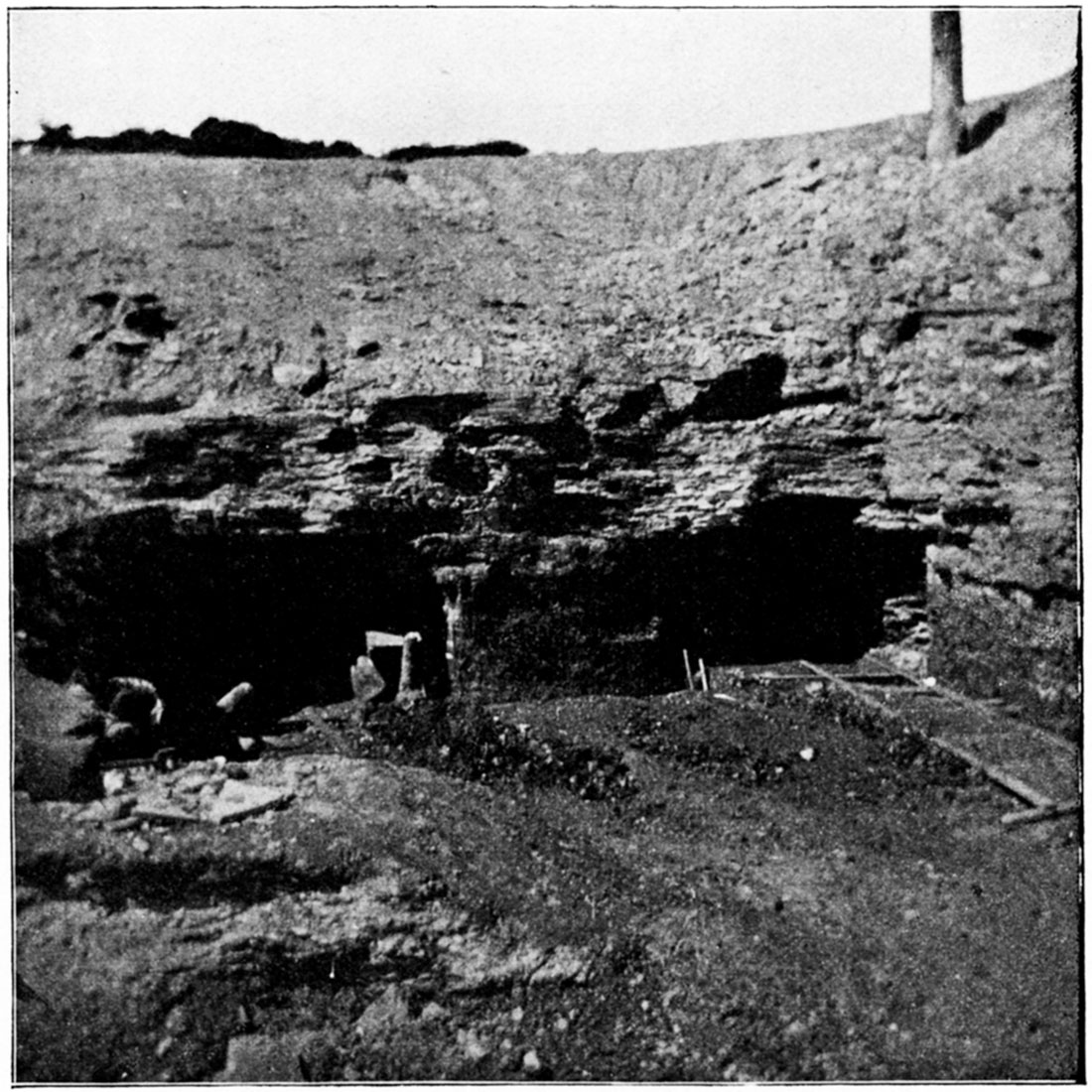
Plate XL—Old strip pit, Pittsburg. (Photographed by Crane, 1897.)
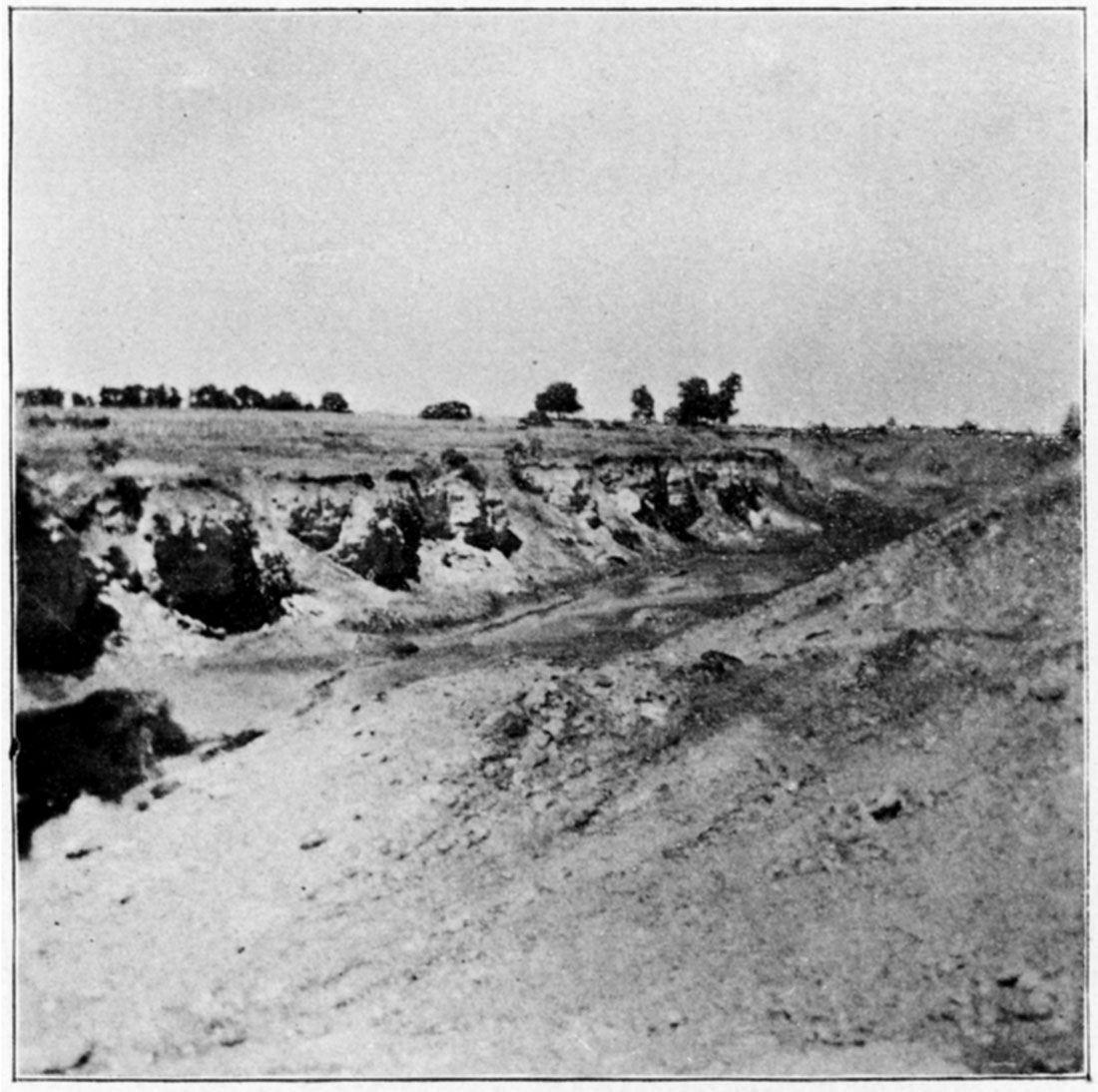
Plate XLI—Strip pit mining, Scammon. (Photographed by Crane, 1897.)
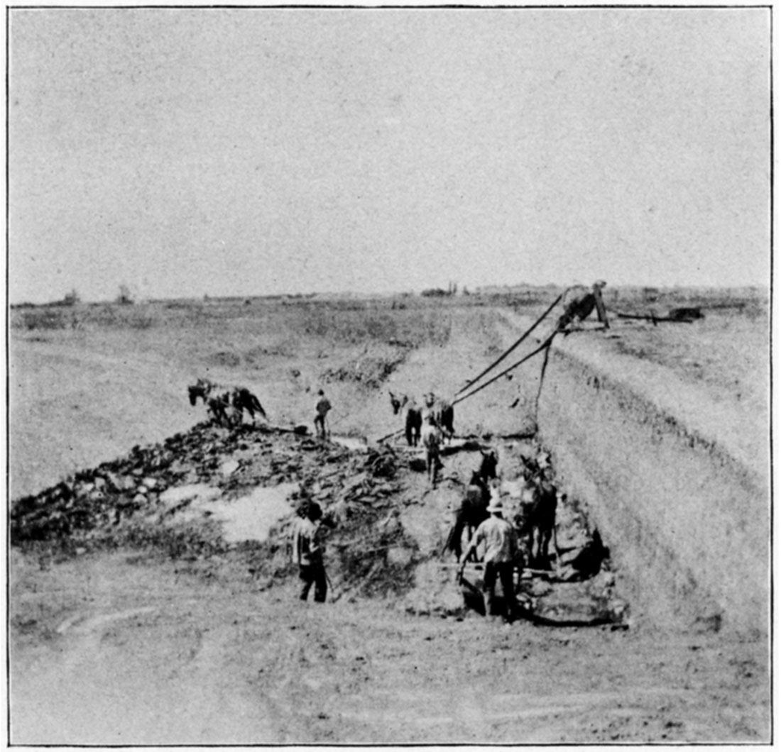
Plate XLII—Drift-slope mine in clay pits, Nesch Brick Yards, Pittsburg. (Photographed by Crane, 1897.)
Method of Mining the Coal
On the side and at right angles with the entry the room is driven or opened. There are several methods employed in loosening and removing the coal from its bed. One method already described in entry driving, is probably the one most generally employed. Figure 42. Three other methods are also shown in Figures 43, 44, and 45, which differ but little from Figure 42. The principle is the same in all three methods, namely: to make an opening which permits the charge of powder to act, thus loosening up the coal. Powder takes the place almost entirely of hand mining by pick and bar in the thicker coal beds. The drill generally used is a very simple tool and is so arranged that it may be turned upon its horizontal and vertical axes—Figure 46—thus permitting the miner to drill a hole in several widely different directions, with only one setting of the machine: In dry mines the charge is placed the same as in ordinary blasting, but when the mine is wet the charge is liable to become moist before it is fired, and a "firing barrel" is employed to protect it from the water. The firing barrel is an iron or brass tube varying from eighteen to twenty-four inches in length. The fuse is placed inside the tube and both introduced into the charge. The charge and end of tube are then inclosed in. a tight wrapper of oiled paper or some substance impervious to water. The charge is then introduced into the drill hole, tamped, and fired, the fuse being within the iron tube and thus kept from the surrounding moisture.
Figure 44—Horizontal Plan, showing Method of Opening Entry by "Cutting."
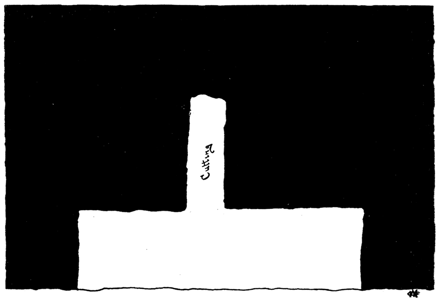
Figure 45—Horizontal Plan, showing Method of Opening Entry by "Cutting."
Cost of Mining
For mine-run coal, or coal in the rough, the miner receives about 30 cents per ton. When the miners are paid for the lump coal only they receive from 50 to 75 cents per ton. When the miner is paid for the amount of mine-run coal he gets out the tendency is for him to become careless and thus break up the coal, producing too large a percent of fine coal. For this reason some operators pay for lump coal only, thus encouraging clean lump mining.
Pillar Building and Gob Packing
Pillars are not built in the room and pillar system but are simply portions of unmined coal left as supports to the roof. They are generally in the form of rectangles from seven to sixteen feet wide and ranging from fifty to one hundred feet long and are formed by the process of driving entries and working rooms. The waste material is used to "gob" up the entrances to rooms and fill up old rooms.
Method of Hauling
All of the entries and hauling ways in use have a system of railways operated by either mules, electric power, or steam power. Mules are used the most. The room tracks are connected with the entry tracks by iron plates upon which the cars are transferred from one track to the other. The room track is built into the room and extends up to the face of the coal, additions being made to it as the face of the coal advances, thus keeping the car in easy reach of the miner. The miner loads the cars and pushes them into the entry where they are transferred on to the empty track. From the entries the loaded cars are hauled to the foot of the shaft by mules—one mule hauling from six to twelve cars in a train. Switches are located along the main: entry generally at the road head. Here empty cars are kept in readiness to be passed into the mine and loaded ones can pass each other and empty cars on the way to the rooms. Turn outs are also provided in some mines, where cars going both ways may pass.
Strip Pit Method
Strip pits are employed only where the coal is quite close to the surface. Plate XL. The character of the material lying above the coal regulates to some extent the depth at which stripping mayor may not be a paying operation. If the roof material of the coal is a hard rock, as limestone or ironstone, of several feet thickness, the expense of removing this material is generally too great to warrant mining in this way. Unfavorable conditions similar to these are found at Fort Scott, although the coal is stripped there in seemingly paying quantities.
In the southeastern part of the state, on or near the outcrop of the main coal strata, where the coal comes close to the surface, and the covering is generally shale or sandstone, it can be stripped at very little expense. From Cherokee county northward to Linn county the stripping of the roof material is accomplished at a cost of about eight cents per cubic yard. The average paying depth of stripping is about ten feet, although in extreme cases as much as twenty or twenty-two feet have been removed. The coal from the strip pits is placed upon the market in direct competition with the mine-run coal, and yet fair wages are made by the strip pit operators. One acre of land bearing a coal stratum of 3 feet 6 inches in thickness yields 4,375 tons of coal. A price of $1.25 per ton would give to the land a value of $5,468.75. If a profit of 15 cents per ton is allowed the profit from an acre of such land is $656.25, and from forty acres, $26,240. The large extent to which the strip pit method has been employed shows plainly the profitableness of coal mining when the coal lies near enough the surface to allow of stripping.
The Method in Detail
The method of stripping is very simple indeed. Lots generally located on the bank of a creek or run, varying from forty-five to a hundred feet in width and from 200 to 400 feet in length are marked out. Scrapers are then employed to remove the material overlying the coal which material is thrown into the creek or hauled out of the pit by roads leading out of the pit ends which are left sloping. Plate XLI. When all of the dirt and rock has been removed the coal is cut through, blasted out, and broken up and then hauled by wagons to the market. The coal mined in this way ought to be cleaner and less pyritiferous (sulphurous) than the mine-run coal as a better opportunity is given to remove the impurities. When the coal has all been removed a new lot is marked off and the denuding process again begun. The material removed is dumped into the pit from which the coal has just been taken, and thus the process is continued until the coal stratum retreats to such a depth from the surface as to render stripping too expensive. At this point drifting is employed, the entries being driven into the banks of the strip pits. Plate XLII. The coal is worked in the entries as has been explained in one or the other of the two systems of mining above described.
Mining Machinery
The advance in coal mining machinery has kept pace with the improvements in machinery for other lines of work. This progress is due to the increased demand for coal and the consequent advancement of coal mining industries in both new and old fields. With the increase in the demand for mining machinery there has been a corresponding increase in the number of manufacturers of it. A list of the more important manufacturers, who are represented by machinery used in the Kansas coal mines, is included in the tabulated data of the principal coal mines of Kansas. Table XII. It is impossible to discuss here in detail the machinery and its adaptation even. to all of the more important mines, but a general description will be given of the machinery, with a more detailed discussion of the construction and operation of the typical forms.
Mining machinery may be divided into two classes, namely: First, pit machinery; second, top machinery.
Under pit machinery may be considered: First, mining machinery proper; second, drilling machinery; third, machinery for transferring coal from the face of the coal to the foot of the shaft—hauling machinery; and fourth, the system of signaling em ployed between the "top" and the "pit."
Top machinery consists of: First, the hoisting apparatus, including the self-dump, scales, and other mechanisms for weighing; second, the coal sorting machinery; third, pumping machinery; and fourth, ventilating machinery.
Pit Machinery
Mining
For several reasons mining machines have not been very successful and therefore have not met with very much favor in the coal mines of the state; one of which reasons is that the coal strata, except in the extreme southeastern part of the state, and at Leavenworth, are too thin for the employment of mining machines to much advantage. The irregularities of the floor and the occurrence of "horse backs," "bells," etc., present great obstacles to the successful operation of such machinery. It may however be said, to the credit of the machines, that if willing operators could be found, the success of coal mining machinery under favorable circumstances, such as are usually found in the Kansas coal fields, would be practically assured. This statement is made in all confidence after having examined the machines and observed them in operation, and after having talked with both mine operators and miners.
The machines are intended simply to undermine the coal, that is, to loosen and remove the underlying clay, the knocking-down and the breaking-up of the coal being accomplished by hand.
The two forms of machines which have been the most successfully operated are the Harrison and Whitman and the Ingersoll, and the John E. Carr patent.
Details of Mining Machinery
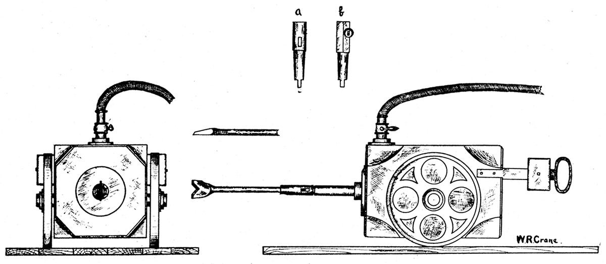
The Harrison and Whitman and the Ingersoll mining machines—Figure 46—are operated by compressed air conducted into a small engine similar in construction to a steam engine. The machine is not over four feet long and about two feet each in width and hight, and consists of an iron cylinder provided with a piston at the end of which is a chuck into which fits the cutting tool or chisel. The cylinder is mounted upon two wheels, and has at one end and on each side a ring-like handle by which the operator can raise or lower the cylinder and direct the chisel against any desired place. At the top and at one end of the cylinder is a valve for controlling the admission of compressed air at this point, and by this valve the speed and power of the machine are regulated. A plank platform about six feet long and four feet wide is constructed, thus giving a smooth even surface upon which to operate the machine. The ease with which this form of machine may be operated, combined with the small space it occupies, would seem to fulfill all conditions requisite for a perfect mining machine, and indeed it has been used quite successfully in the extreme southeastern coal fields of the state. The only difference between the Harrison and Whitman machine and the Ingersoll is in the chucks, which can be seen to the best advantage and understood more readily by referring to a and b, respectively, in Figure 46. Another machine, designed especially for mining under the long wall system, was invented and constructed by John E. Carr, of the Leavenworth Coal Company, Leavenworth—Plate XLIII. This machine has an iron framework about eight feet long and from three to three and one-half feet wide, the main body of which is the field-magnet of a motor. It is operated by electricity. The cutting tools are inserted on the edge of a rotating, horizontal disc, fastened at one side of the machine proper, so that at least one-half of the rotating wheel projects beneath the coal. The armature revolves in a horizontal plane, lengthwise of the machine. On one end is fixed a drum, which rotates in a horizontal plane also, but at right angles to the armature. Upon this drum an iron cable or rope is slowly wound by means of a ratchet wheel, worked by a combination of cog-wheels attached to the armature. The rotating, tool-bearing disc is geared to the armature of the motor. The frame which supports the disc is so attached to the main frame that by turning a hand wheel, connected with the disc-support by a lever, the disc may be tipped at various angles with the horizontal. Of necessity this angle must be small, as will be seen on examining Plates XLIII and XLIV. This machine is so constructed as to move upon a single rail or track, thus raising the cutting disc off the ground. It does excellent work, is simple, yet strong and efficient. The machines as formerly built were found to be too high for efficient and successful operation in the Leavenworth mines. In thicker coal this machine would undoubtedly be a great success.
Figure 46—The Harrison and Whitman and the Ingersoll Coal Mining Machines.
A third form of coal mining machine consists of a shaft five or six feet in length, supported in an horizontal position by two arms, the shaft being armed with cutting tools arranged in four rows. In operation ,the shaft is rotated and pressed against the clay underlying the coal and rapidly loosens it. This cutting tool can be projected into the wall five or six feet.
All the above machines have been operated both in the Leavenworth mines and in the thicker coal beds to the south, and also, to a limited extent, at Atchison.
Drilling Machinery
A large number of different forms of drilling machines have been devised to meet the various conditions of the different formations found associated with coal strata. An instrument to be fairly successful should have a tolerably wide range of adaptability,- the wider the range the greater the chance it has for being universally used.
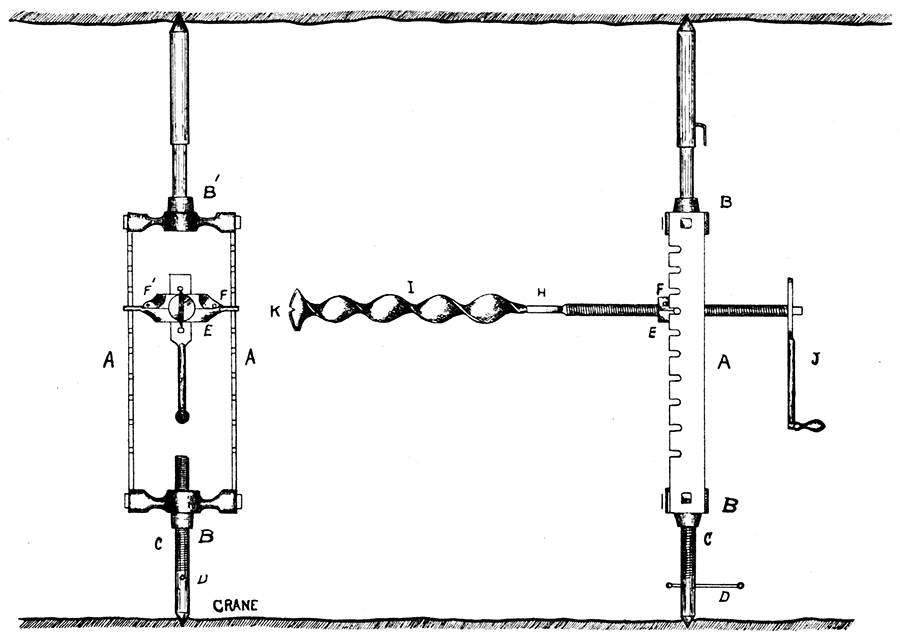
Detailed Description of a Drilling Machine
There is one form of drill which is employed generally throughout the coal mines of the state. It is very simple, yet strong and easily operated, and is easily adjusted to almost any angle, in any plane within the 180 degrees vertical or horizontal arc. It may be operated by one person and is easily taken down and set up. The weight complete is in the neighborhood of thirty pounds.
Plate XLIII—The Carr electric coal mining machine, showing cutting wheel.

Plate XLIV—The Carr electric coal mining machine, front view, showing winding reel for cable.

On consulting Figure 47, the following description will be rendered much plainer. Two side bars, AA, of wrought iron, and notched as seen per cut, are bolted to two end castings, BB'. One of these castings, B', is provided with an extensible leg, the other, B, with coarse pitch screw threads, C, arranged with a sliding rod, D, by means of which it may be run back and forth by hand. Both ends are formed into sharp points which are forced into the roof or side walls and thus prevent the drill frame. from slipping. A block, E, terminating in two rod like arms which fit into the notches on A, thus allowing a rocking or vertical movement of the drill proper, is made into two separate parts, each part bearing one-half of the threads in which the rod bearing the drill works. The other parts of this block are held together by pins, F and F', thus holding the two pieces firmly together and forming a wide cap which allows but little play of the drill rod. This drill rod is from two and one-half to three feet in length and is furnished with threads for very nearly its whole length. On one end of the rod is a rectangular socket, H, a receptacle for the drill blade, I, the outer end being squared up upon which a crank, J, fits. Several openings are made in the crank to fit upon the square end of the drill rod to allow of more or less purchase or speed being given to the drill as the formation to be drilled is hard or soft. The drill blade is a flat steel bar twisted into a spiral or auger-shaped blade, terminating on one end in a semi-circular cutting edge with a "V"-shaped notch in the line of the axis of the blade. The other end of the drill blade is made to fit into the above mentioned rectangular receptacle of the drill rod. The whole mounted and presented sideways and again as it is seen at end is given in Figure 47.
Figure 47—Miner's Drill, as Used Principally in the Crawford and Cherokee County Mines.
Hauling Machinery
Track
The track consists of a T-shaped rail similar to other rolling stock rails, but generally very light. The length of individual rails is immaterial as they are constantly being cut up to adapt the road to new switches and bends, factors which are constantly entering into the economy of mining and in most cases with a great deal of irregularity. At the point where a side track is connected with the main entry track special connections must be arranged, especially when the track is to be changed every few days. Generally an iron plate is placed directly under and bolted to the main and side tracks, the side track being fastened by only one bolt, so that it may be hinged back and forth upon the bolt as a pivot, the plate thus forming a firm, even surface for the rail to move upon, besides acting as a transfer plate upon which to shift the cars from one track to the other. The rails are. spiked to evenly hewn hard wood sticks, or in some cases pieces of sawed timber. The distance between the rails is from two to three feet, more generally above than exactly two feet. When it is possible the track is leveled, but in most cases this is impossible, so that a smooth track is the only condition actually sought.
Cars
The cars used for hauling coal are from four to five feet long and from two and one-half to three feet in width, on the bottom. The floor of the body proper, to which the axles are attached, and also the two sides which rise at right angles to the bottom, are made of hardwood boards bound together with heavy straps of iron. The sides are held to the bottom by the same straps of iron that hold the bottom planks together and are vertical at the bottom, and flaring at the top to increase their capacity and facilitate their unloading. In most cases doors are so hinged to the cars that when the car is to be unloaded the door is raised automatically and the coal is free to slide out. Figure 48. In other cars no doors are used, the larger blocks of coal being placed in the form of a wall across the end of the car and the finer coal filled in between. The two sets of wheels are close together to facilitate the dumping of the cars. Couplings, consisting of an iron loop or eye, are furnished each end of the car, the ends of two cars being connected together by short chains having a hook at each end. The cars have an average capacity of from 1400 to 1600 pounds each.
Figure 48—Automatic Car Door Opener.
Motive Power
Mule power is used most extensively in the Kansas coal mines, but in a few of the better equipped mines steam and electricity are employed. Mules, when well fed and properly handled, make very handy and efficient power, but the expense and trouble of keeping them about the mines is so great that, in the larger mines, it is only a question of time when they will be wholly replaced by steam power.
Steam and electric hauling, when properly employed, have many points of advantage, namely: a saving of time, less labor and expense for the power obtained, and greater convenience. The cable drum, run by either electric motor or steam engine, is generally located at a point near the foot of the shaft. The steel or iron cable is wrapped several times around the drum to prevent slipping. Near the drum is a tension carriage to keep the cable taut. Sheaves are placed at both ends of the system and at the bends, while small rollers are located every few feet along the track and midway between the rails—these keep the cable approximately in the middle of the road. The sheave at the extreme end of the system is from six to eight feet in diameter to start the cable on the return track, which latter is provided with a system of sheaves and rollers as found on the advance track, to guide the cable to the driving drum. In some mines two or more systems are operated, often side by side. The driving drum is connected directly with the engine or motor by means of a system of geared wheels, Mortised wood gears are generally employed to deaden the noise as much as possible. A system of grips is employed by means of which the operator can connect or disconnect at will a car with the moving cable. A pilot car is often employed to which a train of cars is coupled. This pilot car is not used for hauling coal, having simply a seat, a lamp, and two grip levers. Latch-switches are used when roads branch off from the main track; which switches are opened and closed to let the cars pass. To go more into detail regarding this system would be unprofitable and impossible as well, in the present report.
Signaling Apparatus
The signaling apparatus employed in the mines is, in most oases, extremely simple, consisting of a wire, passing over pulleys when a corner is to be passed, through guides, and reaching from the foot of the shaft to the top or engine house. A lever fastened to the wire at the bottom when drawn down causes a hammer to strike an iron plate or bell, thus giving the signal, one or two taps as the case may be. In a few mines the tube transmitter is used, while in still rarer instances telephones are employed. In the shallow mines the voice is relied upon almost entirely for communication.
Top Machinery
Hoisting Apparatus
The hoisting apparatus of a mine consists of: First, the shaft which guides the cages in the upward and downward passage; second, the cages and the cables which lift them; third, the drum upon which the cable is wound in the act of elevating and from which it is unwound in the act of lowering the cages with the loaded and unloaded cars; and fourth, the engine which furnishes the power requisite for raising the cages. All other parts are secondary to the above mentioned ones and will be considered in connection with the particular part of the hoisting apparatus proper with which they are most closely associated.
Towers
There seems to be no special standard for the construction of towers. The elevator part of the tower is but a continuation of the underground shaft timbers, and rises to a hight of fifty to one hundred feet. It is composed—Plate XLV—of four corner timbers which are braced by timbers passing to and firmly mortised in the adjacent corner timbers. The method of bracing differs considerably in towers made by different. contractors, but the most common way is to brace straight across, thus making a square frame every twelve feet. On two opposite sides an extra timber running parallel to the corners and exactly half way between them is bolted to the brace timbers. These are guides upon which the cages slide and are, in fact, the only point on the tower or shaft timbers which the cages touch. Figure 49. The lower part of the tower is built of 8 by 8 inch, or 8 by 10 inch timbers, being mortised together and raised as one piece. Upon these timbers is built the top house which protects the operators from the weather, keeps the machinery dry, and furnishes a covering for the chute which is built in and firmly fastened to the lower timbers of the tower. The upper end of the chute opens into the top house. Above and topping the shaft timbers is a framework, a continuation of the shaft timbers, supporting the two sheaves which guide the cables from the tower house down the center of the shaft. To one side is built the scale and weighing room. Cables or wooden braces keep the tower from rocking backwards and forwards when a load is being raised or lowered, and are on the sides or ends, depending upon the direction that the engine or power house is located from the tower. Stairs fastened to the timbers of the tower are built from the ground to the floor of the top house.
In the "jigger" or "shaker" tower—Plate XLV—the chute is swung on iron bars, RR, the whole being shaken back and forth by an engine, E', situated near the shaft. Tl{e tower built on this plan must needs be much more solidly built than the ordinary parallel-bar screen chutes. Even when bolted and braced in every possible way the whole tower shakes and sways when the heavy chute is jerked back and forth. The parallel bars, K', K'', K''', or perforated plates, are arranged practically the same in the jigger towers as in the stationary, with the exception that in the jigger tower the screens are arranged in steps as the chute descends. By this arrangement the coal is more thoroughly screened and is moved off the screen more rapidly.
Figure 49—Section of Elevator Shaft, showing Cage Ascending the Shaft, The dotted lines show the Bennett Automatic Dump in Operation.
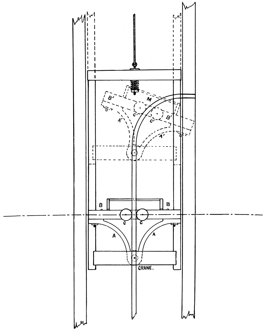
Plate XLV—Top Works of Typical Shaker Shaft.
Cages
The elevator carriages or cages used in the shaft consist of a framework of timbers and iron rods, having a top and bottom.
The cage is a rectangular shaped framework, BCB'C', in vertical section, and PPPP in horizontal section—Figure 50—sliding up and down in the square or rectangular space formed by the shaft timbers, A, and guided by the guiding cleats, LL'. The floor, PPPP, is made of heavy hard wood plank well bolted together. At the corners, PPPP, hard wood timbers, BB', and CC', are fastened and connect the roof with the floor.
In a good many frames these corner timbers, BB' and CC', are iron rods. In those cages not constructed for automatic dumping there is only one bottom, but in the self-dumping cages there are really two bottoms; the lower and true bottom of the cage, usually not floored over; and the upper and false bottom, which is planked, and upon this floor is laid the track upon which the cars stand while the cage is being raised or lowered. The false bottom is so arranged as to be tipped forward at an angle sufficient to allow the coal to slide from the car. Figures 49 and 50.
Figure 50—Section of Elevator Shaft, showing the Hamilton Automatic Dump. The figure to the left shows the Hamilton Dump as attached to the cage. The dotted lines show how the dump works, The figure to the right shows a section through the shaft, bringing to view the floor of cages, with track, guards, and dogs.
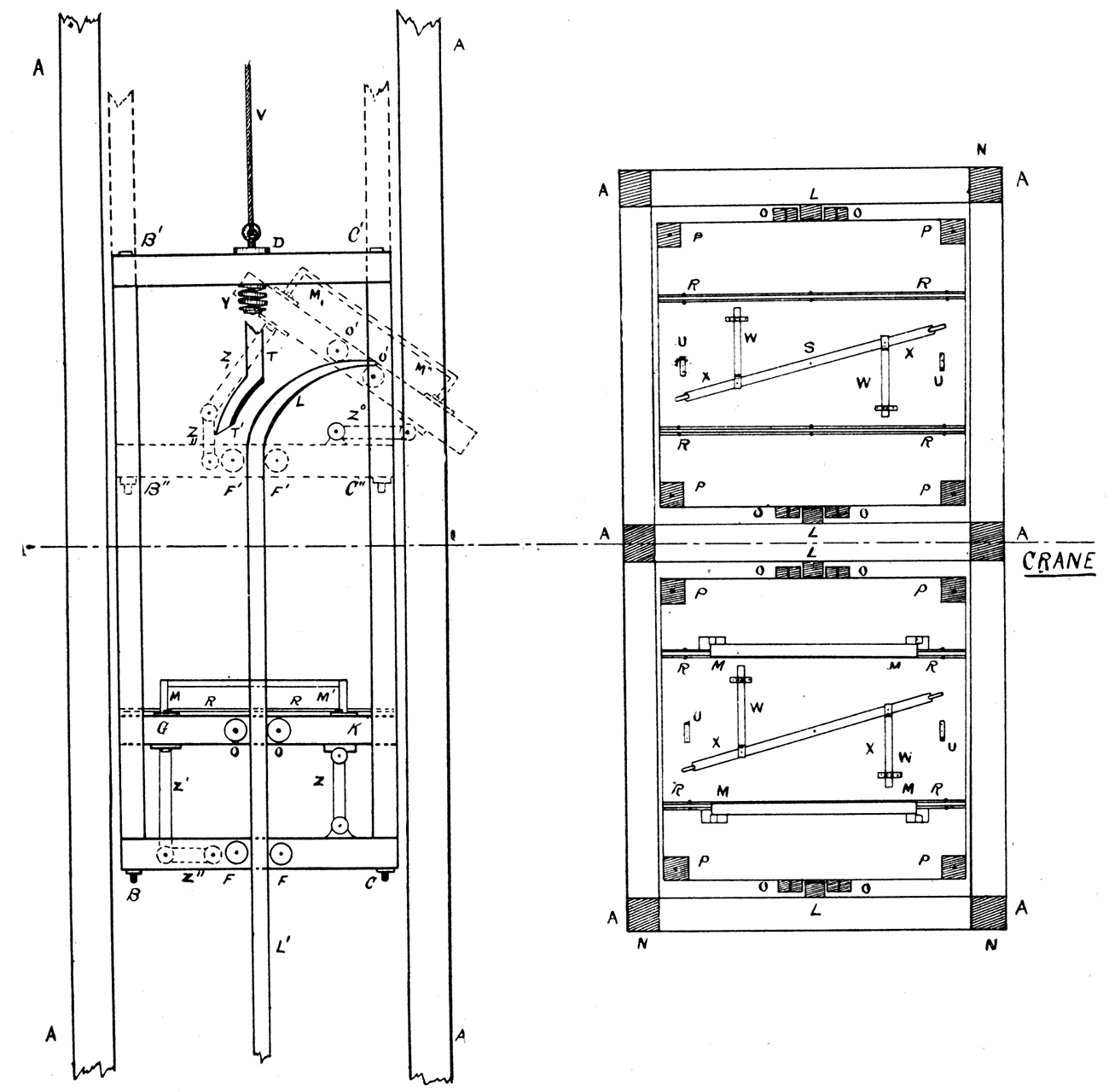
Between the rails of the track is a combination of levers, called a dog, W X, Figure 50, which, when pushed to one side, permit the car to be rolled upon the track, and when pushed back again hold the car from running off. Rollers, F F, fastened to the top and bottom of the cage and to the false bottom in the automatic dumping attachment, rest on each side of the guiding timbers, LL', and thus hold the cage in place. The rollers attached to the false bottom and situated on each side of the guiding timbers cause this bottom to be elevated and tipped when brought in contact with the curve in the -upper part of guides, LL'.
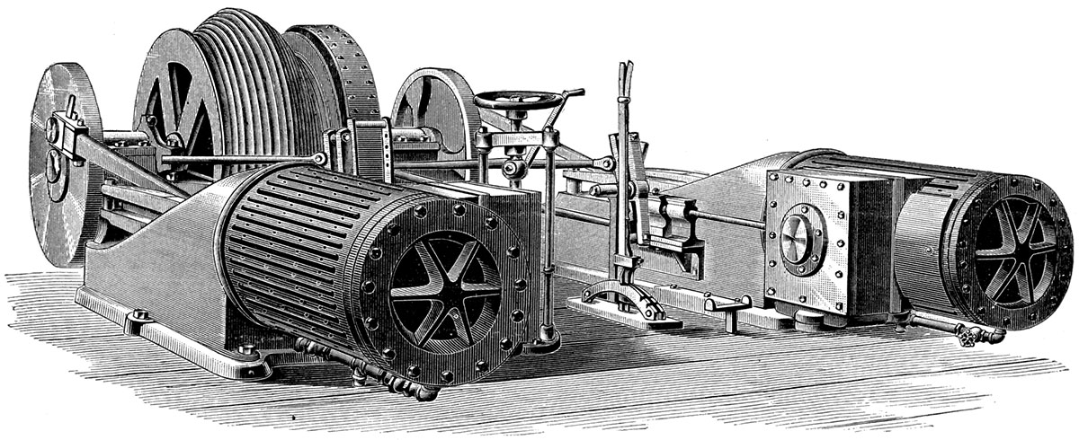
Plate XLVI—The Crawford and McCrimmon double hoisting engine.
The roof of a cage has a framework of timbers, through the central one of which a bolt, D, passes, which bolt passes through a coiled spring, Y, and is then furnished with washer and cap. The head end of this bolt is formed into an eye into which the wire cable, V, is fastened. Figures 49 and 50. This arrangement prevents any sudden or violent jerk or jar being severely felt in the cage. Upon the upper framework is generally fastened a stout iron shield to prevent rocks or coal from falling into the cage.
The guards, M M and M' M', Figure, 50, fit loosely above the wheels of the car while upon the track, so that when the cage is tipped forward the car cannot be thrown from the track. In Figure 50 these guards are shown in the lower drawing of the horizontal section of the cage floor, but not in the upper drawing.
Cables
The cables to support the cages with accompanying load are usually from one to one and one-fourth inches in diameter, although in some of the smaller mines, especially horse-power shafts, three-fourths inch cable is used. The cable is a steel rope, the separate parts of which are malleable steel wires twisted into strands, which in turn are twisted into the main rope. These cables are very durable, having a life of from four to six years and even longer, if care is taken regarding the diameter of the sheaves and if they are protected from the saline and acid water usually found associated with all minerals and with coal as well.
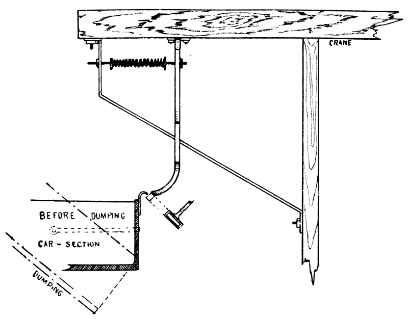
Hand Dumping
As remarked [previously], the car axles are placed close together, bringing the wheels nearly under the middle of the car, in order to facilitate dumping. The car is pushed from the cage upon a short section of level track leading directly to the chute. At the end of the track and at the beginning of the chute the rails are fashioned in to hooks—see plan of tower, Plates XLV and XLVII. The front car wheels entering these loops are prevented from moving onward, whereupon a downward pressure on the front end of the car or a corresponding lift on the back of the car causes it to swing upon the axle of the wheels in the loops, and thus is tipped forward at an angle of about forty-five degrees with the track. In the act of dumping, an arm, as shown in Figure 48, catches into a loop on the gate in the front end of the car and raising the gate allows the coal to slide freely out.
Automatic Dumping
In some of the better equipped mines automatic dumping machinery is employed. In the automatic dumping arrangement the car is not taken from the cage, thus necessitating a closer approach of the chute to the shaft. As explained under the head of "Cages," [previously], the track and dogs on the cage floor and the guards above the car wheels keep the car from rolling off or sliding about during the hoisting and dumping, and hold it firmly upon the cage. The door of the car is opened as in the process of dumping by hand. The actual mechanism which tips the car is attached to the bottom or floor of the cage. Most of the automatic dumps have been designed by the owners or operators of the mines. Those in most common use are, the Hamilton, the Bennett, and the Griffith.
The Hamilton automatic dump consists of an arm, Z, and elbow, Z' Z'', and two rollers, OO, Figure 50. The platform, GK, when level is supported by the arm Z, which stands in a vertical position, and by the arms Z' and Z'', which form the elbow of the joint, Z' Z'', the arm Z' standing vertically while Z'' is in a horizontal position. The guiding timbers, L L', are furnished with a curve at the top which bends in the direction that the coal is to be dumped. The guiding rollers, OO, disposed on each side of the above mentioned timbers, cause the cage floor to be tipped forward when the curve just referred to is reached as the cage ascends the elevator shaft. The vertical arm now becomes horizontal, while the vertical and horizontal arms of the elbow joint make an angle of forty-five and ninety degrees, respectively, with the horizontal. The cage floor is given a tip of nearly forty-five degrees with the horizontal, thus removing the danger of falling coal during the act of dumping. In Figures 49 and 50 that part of the figures in solid lines shows the cage and floor in position for hoisting, the dotted lines show the cage in the act of dumping.
The Bennett automatic dump is much simpler than the Hamilton, consisting of two heavy iron brackets, A, hinged upon a shaft attached to the lower timbers of the cage, the floor, B, being bolted to the top of these brackets. The rollers, C, Figure 49, fastened to the floor of the cage cause it to be tilted forward when the curve, M, in the guiding timber is reached in the ascent. The edge of the floor of the cage is, in this form, also projected beyond the shaft, thus insuring against any coal falling down the shaft while dumping. The Griffith's, automatic dump differs from the Bennett only in the guiding arrangement. Instead of having the guiding timbers, upon which the cage slides, curved at the top, they continue straight to the top of the elevator shaft. A projecting arm or block fastened to the floor of the cage comes in contact with a block fastened to the shaft timbers, this holds back the front edge of the cage floor while the back edge or side rises as the cage is elevated, thus tipping the floor to the required slant.
The automatic dump takes the place of two men to every cage and is a great saving in time as well as labor. The only serious objection raised to its use is the breaking up of the coal, due to the force with which it is thrown into and down the chute from the car.
Hoisting Engines
The hoisting apparatus consists: First, of one or two steam engines—the number depending, as a general rule, upon the capacity of the plant; second, of a drum upon which the cable is wound; and third, of the mechanism for regulating the speed and direction of the rotation of the drum. The drum may be single or double and is generally cylindrical, but where deep mining is necessary conical drums are used. Conical drums have not as yet been employed to our knowledge, in the Kansas coal mines. When the elevator. shaft is single one end of the cable is attached to the drum, the other to the cage. When the shaft is double the cable is wrapped six or more times about the drum, each end being attached to a cage. By this method when one cage is elevated the other is lowered. This necessitates a reversing apparatus so that the cage may be run right handed for a time, then reversed and run left handed, thus raising and lowering the cages in turn. The reverse mechanism is simple and is the same as that used in the locomotive and other engines where a reverse rotation is desirable. A hand regulated shut-off, for the steam, and a brake for stopping the rotation of the drum, at a certain point, are also necessary. A rotating valve, arranged with a long handle and taking the place of the usual hand-wheel shut-off, is the more common form employed. A friction brake is employed and consists of an iron or steel band passing entirely around one end of the drum. One end of this band is securely fastened to the framework which supports the engine, the other end being attached to a lever operated by foot. A slight pressure upon the lever tightens the band about the drum, thus producing a most efficient form of friction brake.
An excellent form of double hoisting engine, with single or double drums, is manufactured by Messrs. Crawford and McCrimmon, of Brazil, Ind., the drum of which furnishes a new feature in hoisting engines. The following extract is taken from the Twenty-sixth Annual Message, page 8: "Being made conical both ways, and having the bulge in the middle, and, grooved from end to end, the rope winds from the small diameter at one end over the large diameter at the middle and thence to the small diameter at the other end. It will be seen that we have the advantage of the small diameter in starting the load easily and slowly, and also in landing it in the same way, while we have the larger diameter at the middle to make speed. Besides, the slow motion of the engine at starting and landing makes the handling of the load doubly slow and easy at these points, while the speed of the engines may be very rapid through the middle of the run, where the speed of the load is further rapidly increased by the larger diameter of the drum."
Scales
There are two forms of scales employed about a mine, namely, the "top" and the" track" scales. The top scales are placed at the top of the elevator shaft, the platform of which is a small portion of the track, sufficiently large for a car to stand upon, lying between the shaft and the chute. The cars are run from the cage upon this track, are weighed, then run forward and dumped into the chute. In those shafts where the coal is dumped automatically the above method is not applicable. In such cases a weighing cage is occasionally employed and consists of a portion of the chute suspended by the scale bars; an iron door forms the lower side of this cage, which door may be raised and lowered at will. In this cage the coal is dumped and weighed, after which a light pressure upon a lever throws open the door and allows the coal to proceed down the chute. The weighing cage does not appear to be in much favor in the Kansas mines, probably due to the extreme rough usage to which scales thus used must be subjected.
The track scales do not differ in the least from the usual rail.road track scales. They are located at the foot of the chute where the car must stand while being loaded. Occasionally they are set in the switch where the cars are run after being loaded. The Fairbanks, Monarch, Howe, and Standard, are the scales most usually found about the Kansas mines, and modifications of which are employed both as top and track scales.
Coal Sorting Machinery
Chutes
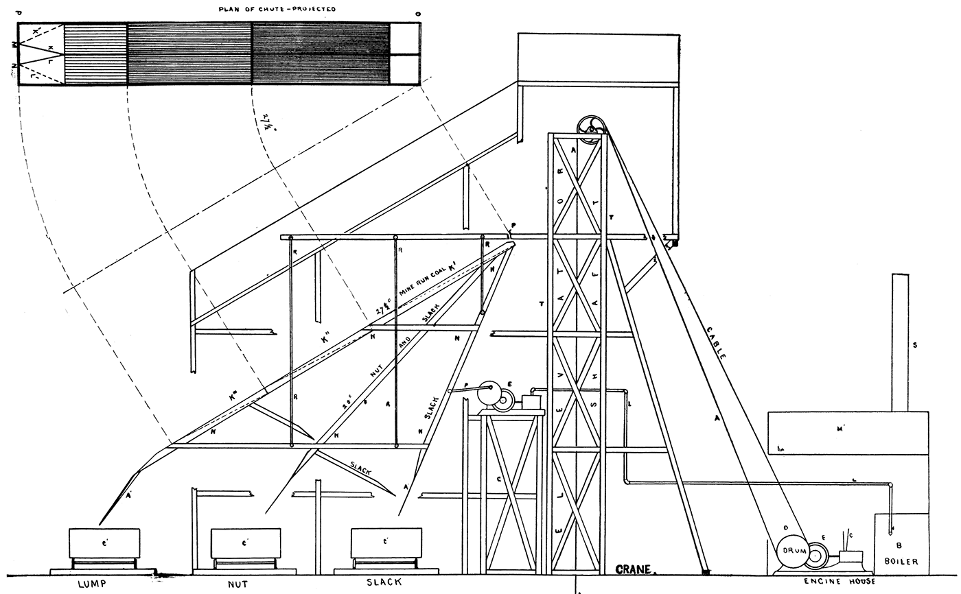
The chute consists of two long inclined planes, A and B, each six feet wide and from twenty to forty feet long. Plates XLV and XLVII. The main part of the chute, AB, makes an angle of twenty-seven and one-half degrees with the floor of the top house, CD, or with the horizontal. The two chutes seen side by side in Plate XLV are separated by an eight or ten inch partition. The upper six feet of the chute is covered with iron plates six feet wide and six feet long. These plates receive the coal directly from the cars. The coal slides from these plates very readily and next passes over a set of parallel bars. In some chutes several screens or sets of parallel bars are employed. Beyond the above mentioned part of the chute the remaining portion makes a smaller angle with the horizontal, generally an angle of about twenty-five degrees. Plate XLVII. This is to break partially the force of the moving coal as it comes from the steeper incline. This portion.is also sheathed with iron or steel plates. The partition mentioned above stops from six to eight feet from the end of the chute to make room for a set of partitions or gates, by means of which the coal may be conducted through one opening or through two as the case may require. The gates, K and L, are swung upon posts, NM, fastened into the end of the chute, OP, about a third of the distance from each side. These doors or gates reach to the end of the partition just above and from this point may be swung to the outer side of the chute, as seen in Plate XLV, K'L'. When it is desirable that the coal be directed into one stream both gates are thrown to the side as K'L'; when the coal needs to be scattered the gates are drawn to the partition, as KL, thus forcing the coal to pass down the chute into which it was first dumped. At the extreme lower end of the chutes aprons, A' and A, are hinged so that they may be raised or lowered to any hight, thus furnishing a means of laterally distributing the coal throughout the car. The chute is made of heavy timbers which are fastened, to the framework which supports the top house.
They are thus made very strong and durable and are also protected from the weather by the roof of the top house, as will be seen in Plates XLV and XLVII. A directing plane—Plate XLVII—making an angle of thirty-four degrees with the horizontal, catches all of the coal that passes through the parallel bar screens and directs it to another plane, which in turn redirects it into the revolving screen. The mine run coal dumped into the main chute passes over the parallel bars; in this transit all but the coarser lumps fall through. The coal which passes over the bars is therefore "lump" coal; that which falls through is "slack" and "egg" and "nut" all mixed together. In passing through the revolving screen, DE, Plate XLVIII, this in turn is separated into slack, egg, or nut, according to its size.
The above described form is only one of the many ways that the screens and directing planes are arranged. Space will not permit of more detailed description of the different forms of chutes.
In the discussion of the towers a short description was given of the shaker shaft and the method of screening therewith.
Screens
Parallel Bars—The parallel bar screens used in the chutes are made of iron bars set edgwise and running parallel with the chute. They are often made in sections so that finer or coarser screen may be substituted. In some cases hard wood planks are used which are also placed edgewise and are bolted together in sections. The plank form of parallel bar screen is used more commonly in both the horizontal and slanting coal sorters. The mine run coal is thrown into the horizontal sorter at a point near the shaft, from which point it is carried along by an endless belt drag—that is two chain belts held apart by wood or iron slats which catch the coal and drag it from one set of screens to another, the distance between the bars of the screen increasing as the coal recedes from the shaft. The coal thus passes from the less coarse to the more coarse screens and is thereby sorted into the different grades, as slack, nut, egg, and lump.
Perforated Screens—Perforated iron plates are often used instead of the parallel bar screens. The perforations are circular in some, square in others. They are also arranged in sections. These screens are not as satisfactory as the parallel-bar form as they present more friction to the coal. For finer coal they are probably better as they do not clog as readily as the parallel forms.
Revolving Screens—Revolving screens are built in the form of a truncated cone. Figure 52 and Plate XLVIII. They are generally about eight feet long and increase from a diameter of about two feet, at the smaller end, to a diameter of about three feet at the larger end. They consist of iron hoops, placed every eighteen inches to two feet and braced to a shaft which forms the axis of the screen, upon which is fastened a coarse wire netting, DE, generally of the same mesh throughout but in rare instances having the size of the mesh increase in passing from the smaller to the larger end. The coal enters the small end and as the screen rotates, the shaft being horizontal, the coal must of necessity pass over a large surface of the screen before emerging from the larger end. An apron, G, catches the fine coal which falls through the screen while that which is too coarse to pass through the meshes passes entirely through the screen in the form of nut and egg, is here caught by an apron, Z, and conducted into the car. The screen is generally operated by a screen engine—an engine built especially for this work—but is frequently run by tumbling-rod or endless chain belt from the pump engines.
Pumping Machinery
In those mines where coal is found at no great depth considerable water is generally met with in the mining operations. In such-mines the pumps for removing the excess of-water are located in the tower proper or in a separate house by themselves, or, in many cases, are placed at the bottom of the shaft not far from the "sump" from which the water is drawn. In exceedingly wet mines sumps are located more or less regularly throughout the mine or at a few well chosen places, at which places pumps are placed, thus requiring several pumps to the mine. In mines of any considerable importance steam pumps are most usually employed; in a few instances pumps run by electricity or electric power are used. In the deeper mines electricity is the best and most economical power obtainable, and is used extensively in the Leavenworth mines.
Plate XLVII—Typical parallel screen shaft.
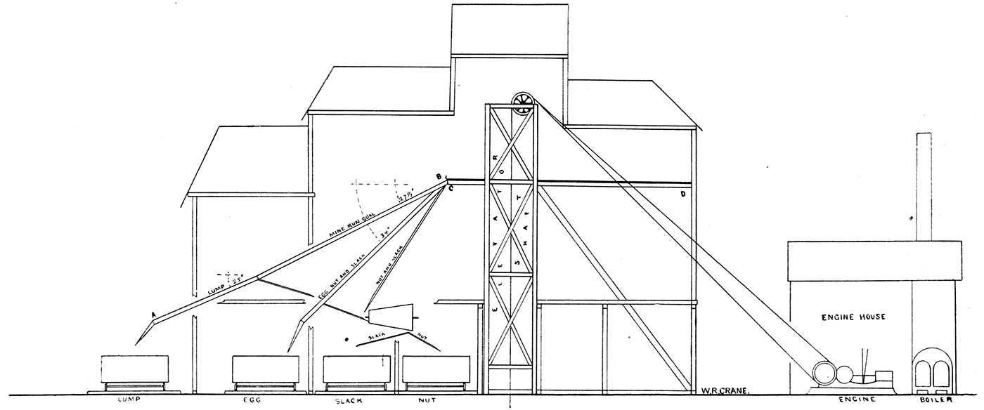
Plate XLVIII—Revolving screen, showing the sorting of coal, as generally used in the coal mines of the state.
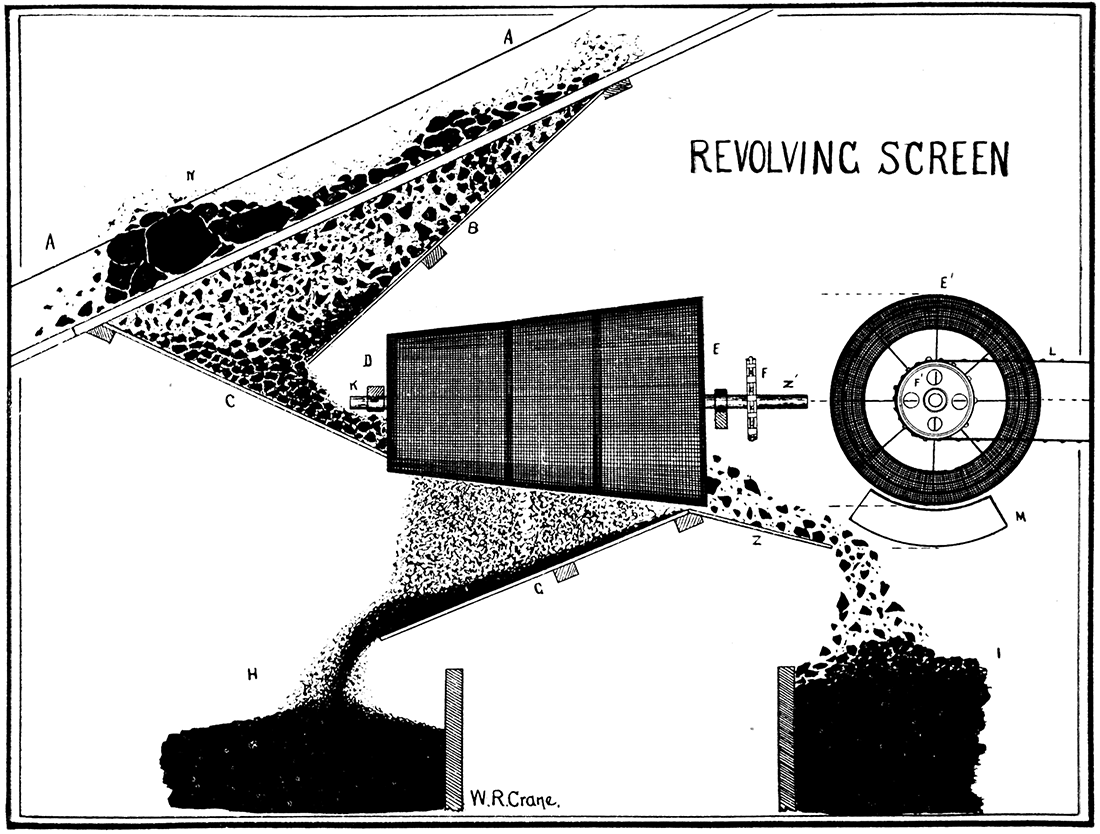
Figure 52—Front View of Revolving Screens.
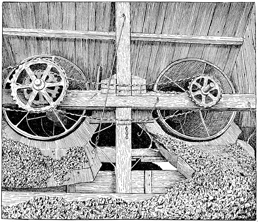
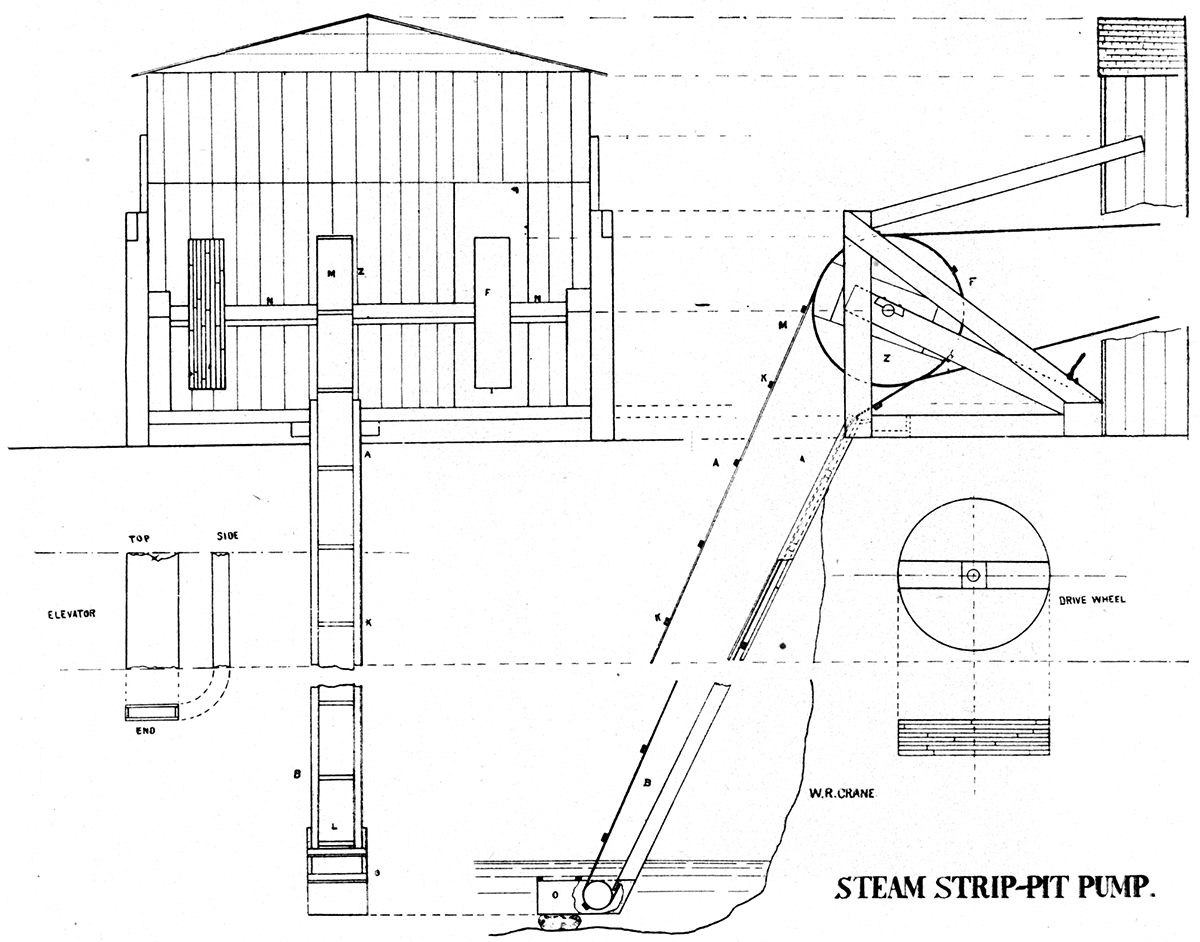
A form of endless belt pump is very common in the shallower mines of the state and also in the strippings. In the mines this form of pump is run by steam power, while in the strip pits horse power is generally employed. The pump as constructed for surface work, as in the strip pits, may be seen in Plate XLIX. The principle, regardless of where used, is the same, so that the strip pit form will be taken as a type of this endless belt pump. The elevator, AB, is a long rectangular tube varying from six to twelve inches in width and from three to four inches in hight, inside measurement. The endless belt, LM, passes through this tube. The belt is canvas upon which cleats, K, are nailed or riveted every twelve or eighteen inches. There is just enough room for the cleated belt to pass easily through the tube and consequently when run at a high rate of speed a large quantity of water will be carried along with the belt by means of the cleats. At the bottom of the elevator is a foot, O, provided with a roller which guides the belt. into the lower end of the tube. The framework of the foot prevents any foreign substance from catching in the belt and being drawn into the elevator. The drive wheel, Z, is fastened to a square axle, N, to which the wheel, F, driven by the engine or horse power is attached. The whole arrangement may be readily seen in Plate XLIX. These pumps are used extensively also in the lead and zinc mines in and about Galena and Joplin.
Steam pumps, built especially to resist the action of acid and saline waters, are used very extensively in the better equipped mines. These pumps are also built very strong and durable so as to stand long and hard usage such as mine pumps alone are subjected to.
Plate XLIX—Steam strip-pit pumps, as generally used to remove water from pits about Pittsburg and Weir City.
Ventilating Machinery
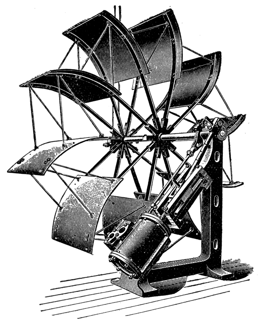
The ventilating currents of air are started and maintained by large fans run by-steam power. These fans—Figure 51—vary in size according to the extent of the mine, but are generally from ten to twenty-five feet in diameter and from three to tell feet in width. The engine which furnishes the power is generally fastened directly to the framework of the fan, the cylinder standing at an angle of forty-five degrees with the vertical and connected directly with the crank wheel of the fan shaft; thus no power is lost in gearing or belting. The arrangement is simple and complete, and as a general rule it receives but little care, running with a head of steam which will give a certain speed, which pressure is maintained by the regulating valve being set .at a certain point where it is left from day to day, and even for weeks, an occasional oiling being the only attention necessary.
Figure 51—The Crawford and McCrimmon Power Fan for Ventilation Purposes. as Used in Mines about Pittsburg and Weir City.
The house in which the fan is placed is generally an isolated building, built directly over the air shaft, and is therefore situated a few yards from the other buildings. :The fan house is built especially to conform to the shape of the fan as much as possible, but is generally rectangular in plan, having straight sides. Plate LI. Upon one side a square funnel-shaped projection is built in which a vertical sliding door is arranged, hung by weighted ropes, so that it may be easily adjusted, thus allowing the opening or closing of the aperture through which the air is drawn in or expelled from the mine, depending upon the intended direction of the air currents. The systems of ventilation will be discussed more in detail under the correlation.
Plate L—Team strip pit pump, Weir City. (Photographed by Crane, 1897.)
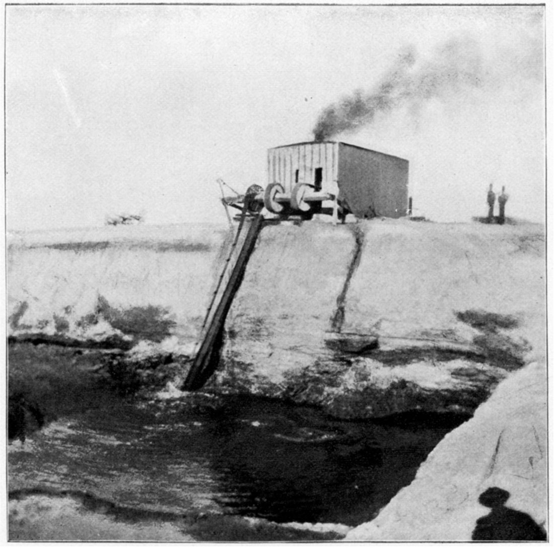
Plate LI—Fan House, as seen at mine near Weir City. (Photographed by Crane, 1891.)
Correlation
From the above descriptions of the various forms of machinery employed in the mine, "pit," and "top," a fairly good idea may be obtained of the machinery actually used. The relation of one part to another part has not as yet been shown, but that may be brought out by a brier description of the processes through which the coal passes in transit from the face of the working to its ultimate resting place in the flat or box car upon the track.
Mining
The coal at the face presents a perpendicular wall, capped with shale; sand, or limestone, and underlaid with fireclay or "black-jack." To remove the coal with as little possible breakage and in the most economical way, both in regard to time and expense, certain machines have been constructed to undermine it, thus providing space for the knocking down of the coal. This is the process employed in the long wall system. In the room and pillar system undermining is frequently employed, but more often, in the Kansas mines, the space into which the coal is loosened is opened by hand and passes vertically through the coal stratum. The drilling machine is then employed to furnish openings into which charges of powder are placed, the powder being the principal factor in loosening the coal.
Transportation
After the coal has been loosened it is immediately loaded into the cars by hand or is "buggied" to the entries where the car stands upon the track and is there loaded. The car is then pushed into a main entry where it is coupled with several other cars and, hauled by mule or steam power to the foot of the shaft. It is then uncoupled from the other cars and run onto the cage of the elevator which stands at the same level as the track of the entry or main hauling way.
Hoisting of Coal
At a given signal the hoisting engine is started and the cage with its load. of car and coal is then started up the elevator shaft. If the cage be double decked, that is, has two floors and a track upon each floor, two cars are hoisted at the same time. In passing upwards, near the top of the elevator shaft and but a few inches below the level of the track in the top, the cage strikes and raises to a vertical position two plank structures, hinged at the lower sides to the shaft timbers. These two frames falling back to their former position, the cage descending rests upon them and the track on the floor of the cage stands level with the track of the top house. The car is then pushed from the cage upon the top track, thence upon that portion of the track which is upon the top scale platform where it is weighed. After weighing the car is run to the head of the chute and dumped.
Sorting of Coal
In sorting, the mine run coal is thrown into the chute, where it is separated by the parallel bar screens, generally into two grades: lump-and the mixture of egg, nut, and slack. In some cases other parallel bar screens still further separate the mixture of egg, nut, and slack, while in other cases the mixture is passed through a rotating screen. In many towers the screening of the coal is accomplished entirely by parallel bar screens, while a still more commonly employed system is the use of both parallel bar and revolving screens. From the respective screens the coal is conducted to box or flat cars, which are weighed and are then ready for transportation.
Drainage
In coal mining the maintaining of the sanitary condition is absolutely essential. Good air and dry workings are prime requisites in mining. At the bottom of the shaft, and forming a continuation of it, an irregular shaped pit extends some eight or ten feet below the floor of the mine. This pit is called the" sump" and is intended as a reservoir for the surplus water of the mine. Often several sumps are necessary and are connected with the various parts of the mine by ditches or pipes. When pumps are used to remove the water they are located either in or near the sump, .or in the shallow mines are located above ground in a special pump house, but in any case are connected directly with the sump from which collecting place the water is drawn from the mine. In drift mines the series of sumps above mentioned are often connected by iron pipes, acting as siphons, the sump nearest to the surface communicating with a lower level above ground. By this means all of the sumps are kept drained. In still other mines not so well equipped the water is hauled out by means of large wooden buckets or barrels.
Ventilation
One of the most essential factors in successful underground operations of all kinds, but especially in coal mining, is the maintaining of a good system of ventilation. This is especially necessary in coal mining as considerable gas is given off by the coal exposed by the mining operations. The setting up and maintaining of an air current is comparatively simple in straight passages, as in tunnels, but when a system of side passages is added, which in turn multiplies the number by the addition of other side rooms and passages, the question of ventilation becomes troublesome and perplexing indeed. By the advent of large fans operated by steam power the difficulty has been overcome in part. By means of these fans strong currents of air may be forced into or drawn from the shaft or airway. The special system of ventilation employed in any particular locality is governed entirely by the system of mining employed. As there are two general systems operated in the Kansas coal fields, the system of ventilation employed with each will be discussed.
In the long wall system of mining the main shaft is used as the down draught, or inlet for the air into the mine, while another opening into the mine furnishes the up draught, or exit for the air. This arrangement maybe reversed, however, in which case the main shaft is the exit while the air shaft is the inlet for the air current. A simple reversing of the direction of the rotation of the fan changes from one method to the other. When the air enters the mine by way of the main shaft it passes in both directions—see Plate XXXIV—along the main entry to the face of the coal; at these two points the air currents divide, one-half going to the right, one-half to the left. The two currents thus produced follow the face of the coal around, gradually converging till they meet at a point midway of the face of the coal on the side and to the right and left of the main shaft. The two currents coming from opposite directions unite here and proceed to the air shaft a short distance from the main shaft along an air-way at right angles to the main entry. The air shaft is generally located to the right of the main shaft, as one looks toward the north. The air current from the left side must, therefore, cross the main entry before reaching the air shaft. This passage is effected by a cross-way being driven above the main entry and boarded up, to prevent the return current from uniting with the fresh air there entering the mine. The two currents reuniting at the foot of the air shaft are drawn upward by the action of the fan, and thus the ventilation is maintained. If the fan is reversed there would be a reversal of the direction of the air currents, namely: the air would enter the air shaft and would be forced out of the main shaft.
In the room and pillar system of mining an entirely different system of ventilation must be employed, which is, in brief, as follows: The same arrangement may be effected in regard to the inlet and exit of the air as was spoken of in connection with the long wall system of ventilation, but as a general rule the air is forced into the mine at the air shaft and makes its escape at the main shaft. The air passes from the air shaft to the side-way or one of the main-ways. Plate XXXVI. Here the air current would divide and pass in both directions were it not for a door, A, placed in the entry on the opposite side from that in which the air. current is to pass. Being forced to proceed in one direction it passes along the entry for a few feet until a side entry, B, at right angles to the main entry, is met. Here a door, C, placed in the main entry again changes the direction of the current, but this time into a side entry. From this point it passes to the end of the entry and from there is directed to either the right or left by air passages cut through from room to room. The air current thus follows the limit of the workings, P P, around until it comes to the main entry again at D. A door, E, placed in the entry again shifts the direction and prevents its return to the exit before it has passed around the mine. A cross passage, F, connecting the two main entries, allows the air current to pass to the opposite side of the mine. From this point it is directed through the workable portion of the mine, G, around to the opposite end of the main entries at H. Another crossway, I, conducts the current from one main entry to another thus allowing it to pass back again to the air shaft side of the mine. Passing through the remaining one-fourth of the mine, K, in a similar manner as through the previous three-fourths it finally reaches a passage way, L, one entry from the one which first conducted it into the mine. This entry in turn conducts the air to the main entry from which it started. Doors, ,Ll[ and N, on each side of the entrance of the side entry into the main entry prevent the current from passing in either direction up or down the entry. A cross-entry, Z, similar to those at the extremities of the main entries conducts the air once again to the opposite side of the mine where it finds exit by way of the main shaft. The passage of the air across the main entry is effected by over-casts as mentioned in the long wall system.
Figure 53—Typical Horse-power Shaft, showing a Common Method of Mine Ventilation by Furnace in Bottom of Shaft.
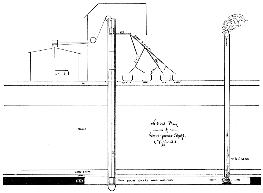
In all coal mining operations some modification of the above described systems is employed, the principle being the same. In less extensive mining operations although the same system is used, the means of setting up and maintaining air currents differ widely. Instead of fans, fires are built below in the pit—Figure 53—which, heating up the air, cause enough draft to set up an air current which introduces fresh air and expels the foul air. This method furnishes a very inefficient and exceedingly unpleasant way of furnishing fresh air to the mine.
In sinking shafts canvas sacks extending from the top of the shaft to the bottom and expanded into a wing at the top to catch the breeze furnish sufficient air for the men working below. This method is applicable only while the shaft is being sunk.
Prev Page--Stratigraphy || Next Page--Chemical Properties
Kansas Geological Survey, Geology
Placed on web Sept. 12, 2018; originally published 1898.
Comments to webadmin@kgs.ku.edu
The URL for this page is http://www.kgs.ku.edu/Publications/Bulletins/Vol3/52_systems.html