Kansas Geological Survey, Open-file Report 2004-62
by Donald O. Whittemore
Kansas Geological Survey
for
Equus Beds Groundwater Management District No. 2
and
National Cooperative Refinery Association
KGS Open File Report 2004-62
Southeast of the City of McPherson, Kansas, saline ground water has been found migrating in a westward direction into the Equus Beds aquifer and the water-supply wells of the oil refinery facility of National Cooperative Refinery Association (NCRA). The Equus Beds aquifer is a part of the High Plains aquifer. The apparent salinity source is from a nearby oil field discovered in the 1930s. Saltwater disposal practices used in the early history of the oil field caused an unknown volume of oil-field brine to enter the aquifer. The study area is also located in an intensive ground-water use control area established because of declining ground-water levels in the Equus Beds aquifer.
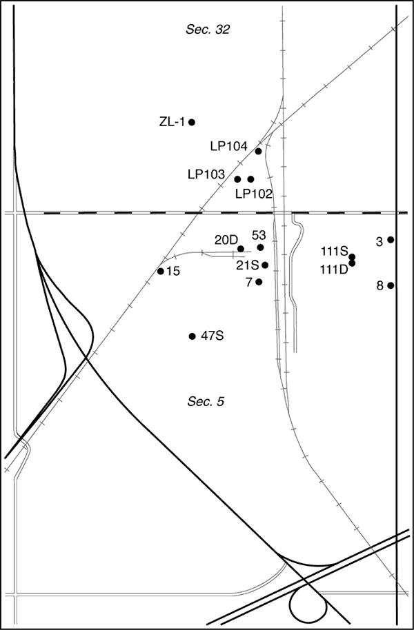
The chloride concentration of the ground water has been increasing, affecting the quality of water in the aquifer to the east of the NCRA facility. Earlier studies determined that the primary source of saline water in the contamination plume east of the facility is oil brine from the Johnson Field (Whittemore, 1997, 2003). Monitoring wells on the east side of NCRA indicate that the saline water is migrating into the area underlying the company's operations. Equus Beds Groundwater Management District No. 2 (GMD2) and NCRA requested that the Kansas Geological Survey (KGS) evaluate the source of the salinity in samples of ground water at wells within the refinery area. The purpose of the study was to characterize the saltwater plume derived from the oil field and help NCRA determine whether there are other local sources of salinity. The study area lies mainly within the north-half of Sec. 5, T. 20 S., R. 3 W., and includes part of the south-half of Sec. 32, T. 19 S., R. 3 W (Figure 1).
Figure 1. Location of the study area south of McPherson in the S/2 of Sec. 32, T. 19 S., R. 3 W. and in Sec. 5, T. 20 S., R. 3 W., and wells sampled on NCRA land as a part of this study.
In 1997, the Kansas Department of Health and Environment (KDHE) and Groundwater Management District No. 2 (GMD2) requested that the KGS determine the sources of ground water salinity in the vicinity of the municipal landfill located southeast of McPherson. The KGS conducted the study for NCRA, the McPherson Board of Public Utilities, and GMD2 in cooperation with KDHE (Whittemore, 1997). Four sources of salinity were considered as possible contributors to the high chloride content of the ground waters: the landfill, the Johnson oil field to the east of the landfill, treated wastewater in Dry Turkey Creek, and the Permian bedrock underlying the Equus Beds aquifer. The study concluded that the primary source of chloride contaminating the ground waters of the Equus Beds aquifer in the landfill area was oil-field brine. The KGS found that oil-brine contamination added from nearly 100 to over 2,700 mg/L of dissolved chloride to the well waters sampled. Increases in the chloride content of ground waters immediately surrounding the north, south, and west sides of the landfill that could be attributed to landfill leachate appeared to have been less than 100 or 200 mg/L.
In 2000, NCRA requested additional assistance in evaluating the source of salinity in the ground waters of the refinery area. NCRA collected samples from multiple wells and the KGS performed the chemical analysis, interpreted the results, and communicated the findings to NCRA. The data for the two samples collected in 2000 from the east side of the main refinery area were included in the evaluation for the Whittemore (2003) study. The data for these wells and the other nine wells within the facility area that were sampled in 2000 are included in this report. Five of these wells were also sampled in 2004.
In 2003, the Kansas Corporation Commission and NCRA requested identification of the saline water source in ground waters on the east side of the refinery and to the east of the southern extension of Main Street, McPherson (also known as old U.S. Highway 81). The results from the study (Whittemore, 2003) indicated that the primary source of chloride contaminating the ground waters of the Equus Beds aquifer in that study area was oil-field brine. Estimates of the dissolved chloride concentration added to the sampled ground waters by oil-brine contamination ranged from nearly 100 mg/L to well over 8,000 mg/L based on the geochemical analysis of the data. The probable oil-brine source is directly to the east of the study area in the Johnson oil field.
The 2003 study hypothesized that dense saltwater from the past surface disposal of oil brine or from leaks in disposal wells and lines in the oil field flowed primarily downwards through the permeable unconsolidated sediments of the shallow Equus Beds aquifer until reaching less permeable clay layers or the shale of the Permian bedrock. If some brine had been allowed to flow along surface drainages, infiltration of part of the brine along the drainage courses could also have contaminated the underlying aquifer. Brine diluted by movement through the aquifer to a salinity low enough that density effects were small could have migrated in the direction of ground-water flow that is generally to the west. Dense saltwater at the base of the unconsolidated aquifer would have moved along the shale bedrock surface in a generally westward direction due to the slope of the aquifer base to the west toward the McPherson channel. The westward migration of denser saltwater and dispersion of saline water by the ground-water flow likely carried the contamination into the 2003 study area.
The 2003 study (Whittemore, 2003) indicated that a small amount of slightly saline water in Dry Turkey Creek could be infiltrating into the Equus Beds aquifer and adding to the chloride content of shallow ground waters just west of the creek and to the east of the refinery. Most of the chloride in the creek water downstream of the discharge point where treated municipal wastewater of McPherson enters is expected to have come from the wastewater. The expected source of chloride in the treated wastewater is the discharge of saltwater from conventional home water softeners used in McPherson; the saltwater is derived from the dissolution of rock salt used to regenerate the softeners. The greatest addition of chloride from the water-softener salt source to the shallow ground waters that were sampled was estimated to be less than 200 mg/L. Geochemical interpretation of data for Turkey Creek water suggested that some samples had additional chloride from oil-brine contamination. Whether this oil-brine contamination was in the ground-water source for the McPherson municipal supply or added to the municipal wastewater stream was unknown.
Staff of NCRA collected eight water samples from NCRA monitoring wells on September 30, 2004, and sent them to the KGS for analysis. The samples were collected using a Grundfos submersible pump. A volume of 25 to 170 gallons was pumped from the wells before sampling, except for wells MW 7 and 21S for which there was only about a foot of water in the casing due to a lower water level in the aquifer than when the well was constructed. All samples were placed in polyethylene bottles and shipped to the KGS by Federal Express. Collection information for the samples and other samples collected in 2000 and 2003 from the main refinery area (Sec. 5, T. 20 S., R. 3 W. and the S/2 of Sec. 32, T. 19 S., R. 3 W.) and sent to the KGS is summarized in Table 1.
Table 1. Location and collection information for ground waters sampled within the main area of the NCRA facility in McPherson County for this study and earlier investigations and analyzed by the Kansas Geological Survey.
| Sample identification |
Legal location | Screened interval, ft bls |
Collection date |
Collection time |
Collector name and agency |
Sample notes |
|---|---|---|---|---|---|---|
| Ground water sampled in 2004 | ||||||
| MW 7 | 20S-3W-05ABD | 33-83 | 9/30/2004 | 13:40 | Brian Powers, NCRA | Hydrocarbon odor, ~1 ft of water in casing |
| MW 15 | 20S-3W-05BAD | 65-150 | 9/30/2004 | 10:40 | Brian Powers, NCRA | |
| MW 20D | 20S-3W-05ABC | 60-150 | 9/30/2004 | 11:18 | Brian Powers, NCRA | Hydrocarbon odor |
| MW 21S | 20S-3W-05ABD | 63-83 | 9/30/2004 | 13:30 | Brian Powers, NCRA | Hydrocarbon odor, ~1 ft of water in casing |
| MW 53 | 20S-3W-05ABD | 58-158 | 9/30/2004 | 11:46 | Brian Powers, NCRA | Hydrocarbon odor |
| MW 111D | 20S-3W-05AAD | 153-183 | 9/30/2004 | 9:51 | Brian Powers, NCRA | |
| MW 111S | 20S-3W-05AAD | 85-110 | 9/30/2004 | 10:02 | Brian Powers, NCRA | Hydrocarbon odor |
| MW ZL-1 | 19S-3W-32CDA | 74-89 | 9/30/2004 | 13:05 | Brian Powers, NCRA | |
| Ground waters sampled in 2003 | ||||||
| WW 8 | 20-03W-05AAD | 118-158 | 3/14/2003 | pm | Jeff Klock, KCC | |
| Ground waters sampled in 2000 | ||||||
| WW 3 (3D) | 20-03W-5AAA | 115-160 | 3/15/2000 | 11:19 | Kurt Shobe, NCRA | Hydrocarbon odor |
| WW 8 (8D) | 20-03W-5AAD | 118-158 | 3/15/2000 | 11:30 | Kurt Shobe, NCRA | |
| MW 15D | 20S-3W-05BAD | 60-150 | 3/15/2000 | 11:50 | Kurt Shobe, NCRA | |
| MW 20D | 20S-3W-05ABC | 60-150 | 3/15/2000 | 12:05 | Kurt Shobe, NCRA | |
| MW-21S | 20-03W-05ABD | 63-83 | 3/15/2000 | 12:40 | Kurt Shobe, NCRA | Hydrocarbon odor |
| MW-47S | 20-03W-05BDA | 55-80 | 3/15/2000 | 11:40 | Kurt Shobe, NCRA | Hydrocarbon odor |
| MW 53D | 20S-3W-05ABD | 58-158 | 3/15/2000 | 12:25 | Kurt Shobe, NCRA | Hydrocarbon odor |
| LP-102 | 19S-3W-32DCC | 80-100 | 3/15/2000 | 13:00 | Kurt Shobe, NCRA | |
| LP-103 | 19S-3W-32DCC | 73-93 | 3/15/2000 | 13:20 | Kurt Shobe, NCRA | |
| LP-104 | 19S-3W-32DCA | 73-93 | 3/15/2000 | 14:20 | Kurt Shobe, NCRA | |
| ZL-1 | 19S-3W-32CDA | 75-89 | 3/15/2000 | 13:50 | Kurt Shobe, NCRA | |
The KGS filtered the water samples through 0.45 (m membrane filter paper before analysis. Specific conductance was measured to estimate chloride concentrations and determine dilution factors for the optimum concentration range of the analytical method. Chloride, sulfate, bromide, total inorganic iodine, and iodate concentrations were determined using automated colorimetric methods on a Technicon AutoAnalyzer II. The chloride concentration was corrected for the effect of dissolved bromide in the analytical method. Dissolved iodide was computed from the total inorganic iodine and iodate concentrations and used to correct for its effect on the measured bromide in the analytical method. The bromide concentration in all samples was also confirmed by adding a spike of bromide equivalent to 0.1 mg/L to diluted aliquots of the samples such that the total bromide was in the middle of the standard concentration range (highest standard concentration is 0.5 mg/L). The bromide recovery range was 99.3-109.2% and averaged 103.4%. Five of the eight samples had a strong hydrocarbon odor and also contained low sulfate concentration (3 mg/L or less). A qualitative turbidimetric analysis based on addition of barium sulfate pillows confirmed that the sulfate concentration was low in all of these samples. The estimated maximum error in the chloride determinations is 3%, in the sulfate measurements is 4% for the concentrations >20 mg/L and 10% for the contents <4 mg/L, in the bromide determinations is 5% for the concentrations >1.3 mg/L and 10% for the values <1.3 mg/L (or 0.05 mg/L, whichever is larger), and in the measured iodine is 10%. The error estimates are based on data periodically collected for samples spiked with standards, including the bromide spikes run for this study, results from participation in the standard reference water program of the U.S. Geological Survey, and the effect of the error in iodine measurements on the interference correction in the bromide determination.
Laboratory information and chemical data for the ground-water samples collected in 2000 and 2004 within the NCRA facility are listed in Table 2 along with the one sample collected in 2003 within the facility area. A few of the bromide values for the 2000 samples are slightly larger than originally reported due to a small revision in the correction factor for the effect of dissolved iodide in the bromide analytical method.
Table 2. Chemical data and mass constituent ratios for samples listed in Table 1 and analyzed by the Kansas Geological Survey.
| Sample identification |
Sample date |
KGS lab no. | Sp.C., microS/cm |
SO4, mg/L |
Cl, mg/L |
Br, mg/L |
I, mg/L |
Br/Cl x 104 | SO4/Cl | I/Cl x 106 |
|---|---|---|---|---|---|---|---|---|---|---|
| Ground waters sampled in 2004 | ||||||||||
| MW 7 | 9/30/2004 | 040095 | 9870 | 1.2 | 3071 | 1.16 | 1.19 | 3.8 | 0.00039 | 387 |
| MW 15 | 9/30/2004 | 040090 | 1780 | 25.9 | 304 | 1.43 | 0.112 | 47.0 | 0.0851 | 368 |
| MW 20D | 9/30/2004 | 040091 | 2340 | 2.1 | 446 | 0.85 | 0.47 | 19.1 | 0.0047 | 1060 |
| MW 21S | 9/30/2004 | 040094 | 3500 | 2.8 | 834 | 0.75 | 1.30 | 9.0 | 0.0034 | 1560 |
| MW 53 | 9/30/2004 | 040092 | 2950 | 1.3 | 674 | 0.20 | 0.57 | 3.0 | 0.0019 | 852 |
| MW 111D | 9/30/2004 | 040088 | 6630 | 35.2 | 2151 | 8.50 | 0.0108 | 39.5 | 0.0164 | 5.02 |
| MW 111S | 9/30/2004 | 040089 | 1090 | 3.0 | 134 | 0.25 | 0.049 | 18.7 | 0.022 | 364 |
| MW ZL-1 | 9/30/2004 | 040093 | 2850 | 183 | 656 | 0.82 | 0.0163 | 12.5 | 0.279 | 24.9 |
| Ground water sampled in 2003 | ||||||||||
| WW 8 | 3/14/2003 | 30047 | 3840 | 48.6 | 1086 | 4.31 | 0.0137 | 39.7 | 0.0447 | 12.6 |
| Ground waters sampled in 2000 | ||||||||||
| WW 3 (3D) | 3/15/2000 | 000049 | 1370 | 46.7 | 238 | 0.71 | 0.086 | 29.8 | 0.196 | 361 |
| WW 8 (8D) | 3/15/2000 | 000050 | 2080 | 35.5 | 484 | 1.89 | 0.0251 | 39.1 | 0.0733 | 52 |
| MW 15D | 3/15/2000 | 000046 | 1600 | 8.5 | 250 | 0.65 | 0.070 | 25.9 | 0.0340 | 280 |
| MW 20D | 3/15/2000 | 000047 | 1460 | 3.2 | 174 | 0.72 | 0.38 | 41.3 | 0.018 | 2190 |
| MW-21S | 3/15/2000 | 000054 | 4290 | 5.4 | 1068 | 0.19 | 1.25 | 1.8 | 0.0051 | 1170 |
| MW-47S | 3/15/2000 | 000055 | 2370 | <2.5 | 458 | 3.15 | 0.39 | 68.7 | <0.005 | 852 |
| MW 53D | 3/15/2000 | 000048 | 2220 | 0.5 | 397 | 0.28 | 0.48 | 7.1 | 0.0013 | 1210 |
| LP-102 | 3/15/2000 | 000051 | 2430 | 360 | 305 | 0.76 | 0.147 | 25.0 | 1.18 | 482 |
| LP-103 | 3/15/2000 | 000052 | 2070 | 181 | 254 | 0.64 | 0.0469 | 25.2 | 0.713 | 185 |
| LP-104 | 3/15/2000 | 000053 | 2600 | 198 | 519 | 0.66 | 0.0129 | 12.7 | 0.382 | 24.9 |
| ZL-1 | 3/15/2000 | 000056 | 1820 | 272 | 183 | 0.39 | 0.0172 | 21.4 | 1.49 | 94.0 |
Unconsolidated sediments, including clay, silt, sand, and gravel, primarily of Quaternary age, underlie the study area. The saturated sediments compose part of the Equus Beds aquifer. The bedrock underlying the unconsolidated sediments is the upper part of the Permian Wellington Formation, which consists of shale and thin beds of limestone, dolomite, siltstone, gypsum (CaSO4 • 2H2O), and anhydrite (CaSO4). Although most of the Wellington shale is gray and bluish-gray, some beds are maroon and green near the top of the formation. The Hutchinson Salt Member occurs in the middle of the Wellington Formation and comprises primarily rock salt with lesser amounts of shale and anhydrite (Williams and Lohman, 1949; Leonard and Kleinschmidt, 1976). The Hutchinson Salt Member thins in an easterly direction in McPherson County. Part of this is due to the removal of the salt during dissolution by ground water and part because the original thickness thins across the county. The eastern margin of the "lost-circulation zone" or "saltwater aquifer" of the Wellington Formation formed by dissolution lies a few miles to the west of the study area (Leonard and Kleinschmidt, 1976; Gogel, 1981). Gogel (1981) indicated that some subsurface salt remains in the main body of the Hutchinson Salt Member a couple miles to the northwest of the study area and in a small isolated area a few miles to the east. Thus, thin beds of salt could possibly still exist at depth in the bedrock below the study area.
The bedrock surface underlying the High Plains aquifer south of McPherson slopes to the west from the Johnson oil field to the area underlying the NCRA facility (Figure 2). The depth to bedrock ranges from 62 feet on the east-central side of Sec. 34, T. 19 S., R. 3 W. (the west side of the Johnson oil field), to approximately 160-170 feet along the east side of the main NCRA facility (along the east side of Sec 5, T. 20 S., R. 3 W.) The land surface generally slopes to the west from the Johnson oil field to Dry Turkey Creek within the study area, and then rises gently to the east side of the NCRA refinery (based on the U.S. Geological Survey topographic quadrangle). Depths to bedrock used in Figure 2 are based on a review of lithologic logs associated with well drilling activities. The Equus Beds aquifer thickens to the west due to the presence of a paleochannel in the bedrock surface, known as the McPherson channel.
Figure 2. Schematic geologic cross section along the west-east line of the T. 19 and 20 S. join in R. 3 W. starting from the northwest corner of Sec. 6, T. 20 S., R. 3 W. The northern part of the main NCRA facility lies between mile one and two on the cross section. The water table is a general representation of water-level measurements during the last several years.
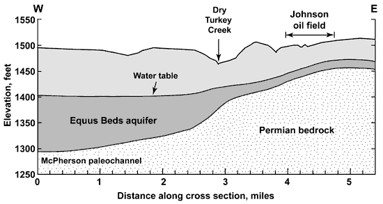
Maps of the water-level surface in the aquifer for the region show a generally westward slope in the study area (Figure 2). The water-table divide between ground-water flow to the Smoky Hill River valley and to the Little Arkansas River valley is south of McPherson (Williams and Lohman, 1949; Leonard and Kleinschmidt, 1976; Gogel, 1981). Comparison of depths to water and to bedrock indicate that the saturated thickness of the Equus Beds aquifer ranges from about 10 feet just to the west of the Johnson oil field to approximately 80 feet along the east side of the main NCRA facility. The saturated thickness in the study area is thinner than existed before development of the aquifer for ground-water supply (based on comparison with water levels in Williams and Lohman, 1949).
As a result of the decrease in the saturated thickness of the aquifer and declining water levels, the Chief Engineer-Director, Division of Water Resources, established the McPherson Intensive Groundwater Use Control Area on March 28, 1980 at the request of Equus Beds Groundwater Management District No. 2. Ground-water development or withdrawal had exceeded the natural recharge of the area and caused ground-water mining. The mining dewatered portions of the aquifer up to 30 ft. The control area encompasses 56 square miles and is located in southern McPherson County and includes the City of McPherson and NCRA. To prevent continued ground-water mining, management provisions were established in the control area and included:
The sources contributing to chloride in the ground waters were identified using the geochemical methods of Whittemore (1984, 1988, 1995). These methods primarily involve plots of the constituent mass ratios bromide/chloride and sulfate/chloride versus chloride concentration, with points for the water sample data and curves for the mixing of different source waters. Each mixing curve is generated using an algebraic equation for conservative mixing of two end-member waters. Conservative mixing refers to the simple mixing of waters without chemical reactions, such as mineral precipitation or adsorption, which could alter the concentrations of one or both of the constituents. The bromide/chloride ratio is multiplied by 10,000 for graphical display to give numbers that range from about one upwards (the lowest mass ratios are near 0.0001 for halite or rock salt dissolution). Logarithmic scales are used in the graphs because they produce a more even distribution (separation) of points for large ranges in concentration and ratios than linear scales. The mixing curves bend in different directions depending on the relative difference in the ratios compared to the difference in the chloride concentrations for the end points.
Figure 3 is a bromide/chloride versus chloride concentration plot containing points for the ground waters beneath the study area (listed in Tables 1 and 2) and oil brines east of the study area. Figure 4 shows points for only those wells that were sampled during different years and for which the KGS performed analyses. Data for the oil brines are reported in Whittemore (2003). The individual points in Figures 3 and 4 are labeled with the well identification number. The two long-dashed curves in Figures 3 and 4 enclose a zone representing the mixing of freshwater with natural Permian saltwater. The freshwater end members for the dashed curves are based on fresh ground waters from the Equus Beds area of the High Plains aquifer (Whittemore, 1984; and data for the Equus Beds Aquifer Mineral Intrusion Study, Young et al., 1998). The saltwater end members for the dashed curves are for saltwaters from the Wellington Formation in the Smoky Hill River valley (Whittemore, et al., 1981) and from the saltwater intrusion area in the western Equus Bed aquifer (Young et al., 1998).
Figure 3. Bromide/chloride versus chloride concentration for ground waters in the study area and oil brines east of the study area. The solid curves represent the mixing of freshwater or slightly saline water with oil brine. The dashed curves represent the mixing of freshwater with halite-dissolution brine. Each pair of curves encloses a zone of mixing. A larger version of this figure is available.
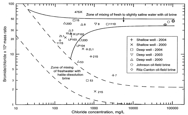
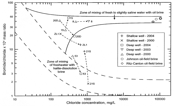
Figure 4. Bromide/chloride versus chloride concentration for ground waters in the study area sampled in two different years and oil brines east of the study area. The solid and long-dashed curves are the same as in Figure 3. The short-dashed curves represent the mixing between the waters sampled in two different years from each well. A larger version of this figure is available.
Freshwaters from the public water supply wells (nos. 7 and 10-14) of McPherson in the Equus Beds aquifer that are located within 1.5 miles of the western side of the NCRA facility had chloride and sulfate concentrations in the ranges 21-51 mg/L and 18-48 mg/L, respectively, when sampled in 1995 and 1997 (Table 3). The average chloride and sulfate values for these samples are 35 mg/L and 28 mg/L, respectively. If the data for well no. 7, which is located closer to McPherson than well nos. 10-14, are not included, the chloride and sulfate concentration ranges are 21-43 mg/L and 18-30 mg/L, and the average values are 32 mg/L and 24 mg/L, respectively. Waters sampled from McPherson well nos. 2-5, 8, and 9 located to the north of the study area had a higher range in chloride (40-86 mg/L), potentially indicating some disperse local sources, and a similar range in sulfate content, (16-44 mg/L) (Table 3). The KGS sampled an irrigation well in the NW/4 of Sec. 31, T. 19 S., R. 3 W. in the summer of 1980 (Hathaway et al., 1981); the chloride and sulfate concentrations in the sample were within the lower range for the municipal wells (Table 3).
Table 3. Chemical data for McPherson municipal well waters (Kansas Department of Health and Environment) and an irrigation well to the west of the study area (Hathaway et al., 1981).
| Well No. | Location | Date | Cl, mg/L | SO4, mg/L | SO4/Cl |
|---|---|---|---|---|---|
| McPherson public water-supply wells | |||||
| 2 | 19S-3W-29DBAA | 11/28/1988 | 77.6 | 44.0 | 0.567 |
| 3 | 19S-3W-29DACB | 11/28/1988 | 68.8 | 37.0 | 0.538 |
| 4 | 19S-3W-29DDCB | 11/28/1988 | 55.8 | 26.0 | 0.466 |
| 4 | 19S-3W-29DDCB | 3/22/1995 | 48.9 | 24.0 | 0.490 |
| 4 | 19S-3W-29DDCB | 2/10/1997 | 49.9 | 28.5 | 0.570 |
| 5 | 19S-3W-29ACAD | 11/28/1988 | 61.8 | 24.0 | 0.388 |
| 2, 3, 5 | 19S-3W-29 | 3/22/1995 | 85.8 | 31.5 | 0.367 |
| 2, 3, 5 | 19S-3W-29 | 2/10/1997 | 86.1 | 34.6 | 0.402 |
| 7 | 19S-3W-31AAAA | 3/22/1995 | 46.6 | 46.7 | 1.003 |
| 7 | 19S-3W-31AAAA | 2/10/1997 | 49.7 | 47.7 | 0.959 |
| 8 | 19S-3W-20CAAB | 3/22/1995 | 40.0 | 15.9 | 0.397 |
| 8 | 19S-3W-20CAAB | 2/10/1997 | 41.9 | 16.2 | 0.385 |
| 9 | 19S-3W-20CCDC | 3/22/1995 | 51.0 | 21.3 | 0.417 |
| 9 | 19S-3W-20CCDC | 2/10/1997 | 48.7 | 21.6 | 0.444 |
| 10 | 19S-3W-31ADDA | 3/22/1995 | 40.9 | 29.4 | 0.719 |
| 10 | 19S-3W-31ADDA | 2/10/1997 | 42.6 | 30.3 | 0.713 |
| 11 | 19S-3W-31DCCC | 3/22/1995 | 20.9 | 20.2 | 0.966 |
| 11 | 19S-3W-31DCCC | 2/10/1997 | 21.5 | 17.5 | 0.812 |
| 12 | 20S-3W-06BBBB | 3/22/1995 | 26.6 | 24.2 | 0.911 |
| 12 | 20S-3W-06BBBB | 2/10/1997 | 31.0 | 25.9 | 0.836 |
| 13 | 20S-4W-01DAAA | 3/22/1995 | 34.7 | 23.5 | 0.677 |
| 13 | 20S-4W-01DAAA | 2/10/1997 | 36.1 | 25.2 | 0.699 |
| 14 | 20S-4W-01DDDD | 3/22/1995 | 34.0 | 20.6 | 0.607 |
| 14 | 20S-4W-01DDDD | 2/10/1997 | 35.5 | 21.3 | 0.600 |
| Irrigation well | |||||
| 19S-3W-31BAB | 7/28/1980 | 21.0 | 19.0 | 0.905 | |
Formation brines associated with hydrocarbons in strata not containing rock salt in Kansas have substantially higher bromide/chloride ratios than saltwater primarily derived from the dissolution of rock salt. The oil-field brine samples for which points are plotted in Figures 3 and 4 have bromide/chloride mass ratios in the range 0.00386-0.00462 (38.6-46.2 after multiplication by 10,000). As described in Whittemore (2003), the oil brines in the Johnson field were produced from Mississippian strata. Points are also included in Figure 3 for oil brines produced from Mississippian strata in the Ritz-Canton oil field (located to the east of the Johnson oil field). Those samples provide an indication of the possible range in chemistry in the brines that have been extracted from these strata in the region in the past. The two solid curves in Figure 3 represent the mixing of oil brine from the Mississippian strata east of the study area with fresh and slightly saline waters. The end point for slightly saline water was chosen for a chloride concentration of 250 mg/L (the recommended limit for drinking water) and a bromide/chloride ratio at this chloride concentration on the upper curve for the mixing of freshwater and halite-dissolution brine. The oil-brine end members for the two solid curves are at greater and lower bromide/chloride ratios than the actual oil brines and represent possible analytical error and additional natural range in the ratios for the Mississippian brines from east of the study area.
There is a substantial range in the bromide/chloride ratios for the saline ground waters represented in Figure 3, indicating multiple sources of salinity. Points for samples fall both within and outside the mixing zones in the figure. This is in comparison with the points for ground waters from monitoring wells to the east of the study area and to the west of the Johnson oil field that are discussed in Whittemore (2003), which all fall either within the zone of mixing of fresh to slightly saline water with oil brine (between the two solid curves) or at chloride concentrations <100 mg/L within the two dashed curves.
The primary source of the high chloride concentration in the monitoring wells sampled to the east of the study area and discussed in Whittemore (2003) is oil-field brine with a bromide/chloride ratio that fits that of saltwater from Mississippian strata to the east of the study area. The general slope in the water table to the west in the region south of McPherson indicates that ground-water flow would also be in this direction. The westward slope of the bedrock surface was described in Whittemore (2003) as an explanation for movement of dense oil brine from the oil field to the west. The westward movement of the oil-brine contamination fits as the primary salinity source for waters from wells WW 3, WW 8, and MW 111D on the eastern side of the main NCRA facility; points for samples from these wells plot between the solid curves of the oil-brine mixing zone. The chloride concentration increased from 2003 to 2004 in the ground water sampled from WW 8 while the bromide/chloride ratio changed little, resulting in a direction on Figure 4 that indicates mixing with the oil brine to the east of the study area. The higher chloride content of the water from MW 111D than from WW 8 in 2004 could be explained by the deeper screened interval of MW 111D than for WW 8, thereby representing the impact of the more concentrated portion of the oil-brine contamination plume resulting from the initial movement of dense brine along the bedrock surface to the east, followed by dispersion of the deep saltwater into a thicker plume. The fresh sample from the shallow well MW 111S (total dissolved solids <1,000 mg/L based on the specific conductance) next to the deep well MW 111D substantiates a vertical gradient in the salinity of ground water on the east side of the main refinery area.
The ground waters from the east side of the main refinery (wells WW 3, WW 8, MW 111S, and MW 111D) lie on mixing lines extending from within the middle of the freshwater and halite-dissolution mixing zone to the average bromide/chloride ratio of the oil brines east of the study area (Figure 5). The average bromide/chloride of the oil brines fits best as also indicated by the discussion of the salinity source for the monitoring wells east of the main refinery area in Whittemore (2003); (see page 9 and Figure 2 of the 2003 report). Whittemore (2003) also indicated that some of the slightly saline water discharged from the wastewater treatment plant of McPherson into Dry Turkey Creek could be seeping into the ground water underlying the creek. The report identified the source of much of the saline water in the wastewater effluent to the creek as dissolution of rock salt (mainly the mineral halite) used in conventional water softeners. This might explain the source of the additional chloride needed to increase the expected range in background chloride content for the Equus Beds aquifer in the area (20-50 mg/L) to the range of about 50-100 mg/L indicated by the freshwater end points for the two curves with short dashes in Figure 5.
Figure 5. Bromide/chloride versus chloride concentration and mixing relationships for ground waters on the east side of the study area. The solid and long-dashed curves are the same as in Figure 3. The short-dashed curves represent the mixing of freshwaters with oil brine such that the curves pass through points for the well-water samples. A larger version of this figure is available.
There is a large range in the chloride concentrations and bromide/chloride ratios of the well water samples collected from the main operations area of the refinery (wells MW 7, 15, 20D, 21S, 47S, LP102, LP103, and LP104) (Figure 3). The water chemistry for the wells in the group that were sampled in multiple years changed substantially (Figure 4). The differences in the chloride concentrations and bromide/chloride ratios are substantial even for those wells that are relatively close to each other, screened at similar depths, and sampled in the same year (shallow wells MW 7 and 21S, and deep wells MW 20D and 53).
The low bromide/chloride ratios for the well water samples with a chloride content of about 400 mg/L and greater, especially for wells MW 7, 21S, and 53, indicate that there is some type of local chloride source that is not oil-brine. The fact that wells MW 7 and 21S are shallow, that deep monitoring wells to the east of the NCRA facility do not yield waters with such low bromide/chloride ratios, and that public supply wells to the west of the NCRA facility are fresh shows that the source of the saline water with low bromide/chloride ratios is not natural intrusion of saltwater from the Permian bedrock below the aquifer. The saline water origin better fits a local source such as the dissolution of chloride salts with low bromide content or hydrochloric acid (see Whittemore [1989] for a saline water study involving hydrochloric acid).
The water sampled from well MW 47S in 2000 had a chloride content of 458 mg/L and a bromide/chloride ratio greater than could be attributed to a source of oil brine from the Johnson oil field to the east of the NCRA facility (Figure 3). The water chemistry suggests either that a small amount of oil brine with a greater bromide/chloride ratio than that of the Johnson field brine was the source or some chemical with a high bromide/chloride ratio affected the ground water. A volume percentage of only about 0.5% of an oil brine with a chloride content of 80,000 mg/L mixed with 99.5 percent of fresh ground water in the area would give a chloride content approximately that of the MW 47S sample.
Figure 6 is a plot of sulfate/chloride mass ratio versus chloride concentration with points for the water samples from the NCRA facility, and freshwaters from supply wells to the west and north (Table 3) and oil brines to the east of the study area. The curves in the figure bound the freshwaters from the supply wells to the west of the study area (McPherson well nos. 7 and 10-14 and the irrigation well) and the oil brines to form a zone of mixing of fresh ground water with oil brine. Points for the well waters on the east side of the facility (MW 3, 8, and 111D) fall within the freshwater and oil-brine mixing zone in Figure 6, just as they fall within the freshwater and oil-brine mixing zone for bromide/chloride versus chloride concentration (Figures 3-5).
Figure 6. Sulfate/chloride versus chloride concentration for ground waters in the study area, freshwater supply wells just to the west of the study area, and oil brines east of the study area. The solid curves represent the mixing of fresh ground water in the Equus Beds part of the High Plains aquifer with oil brine. The oval around the label "47S" represents the approximate location of the point for this monitoring well if the sulfate concentration is assumed to be about that of the detection limit for the water sample (Table 3). A larger version of this figure is available.
Ground waters sampled from the four monitoring wells (ZL-1, LP102, LP103, and LP104) located in the northern part of the NCRA facility (in Sec. 32, T. 19 S., R 3 W., Figure 1) had substantially greater sulfate concentrations (181-360 mg/L) than for all of the other monitoring and supply well samples in Table 2. The highest sulfate content in the rest of the samples from the study area wells was 49 mg/L. Points for the samples fall above the freshwater and oil-brine mixing zone in Figure 6. All four of the wells in Sec. 32 have shallow screened intervals. The relatively high sulfate content and shallow location in the aquifer indicate that either there was a local chemical source with a high sulfate concentration, such as a sulfate salt or sulfuric acid, or there was an appreciable concentration of dissolved solids in water subject to large water loss by evaporation. Ponds shown on the topographic map for this area of the NCRA facility suggest that the evaporation mechanism might be a possibility. For evaporation to be the cause, from 86% to over 90% of the volume of background ground water in the area would need to evaporate to bring the sulfate content to that observed in the 2000 sample from LP102.
All of the water samples with a noticeable hydrocarbon odor (Table 1), except that from WW 3, contained a very low sulfate concentration (<6 mg/L, Table 2). The 2000 sample from well MW 15 also had a relatively low sulfate content (8.5 mg/L). The probable explanation is chemical reduction of sulfate to sulfide during the oxidation of hydrocarbon compounds in the ground water. Points for the samples with low sulfate concentrations plot below the freshwater and oil-brine mixing zone in Figure 6. The sulfate concentration increased significantly in the water sampled from well MW 15 in 2004 in comparison with that collected in 2000. The point for the most recent sample from well MW 15 plots within the freshwater and oil-brine mixing zone; the source of salinity for this water is further discussed later in this report.
Table 2 lists the total inorganic iodine (iodide plus iodate) content and the iodine/chloride ratio of the water samples. The dissolved inorganic iodine concentration of Kansas ground water is usually less than an order of magnitude smaller than the bromide concentration. Like the bromide/chloride ratios, the iodine/chloride mass ratio of halite-dissolution brine is low (between 0.000001 and 0.000005 [1 to 5 as I/Cl x 106] at a chloride content >100,000) (Whittemore et al., 1981, and Whittemore, unpublished data). The iodine/chloride ratio of Kansas oil brines is relatively high; the range in the iodine/chloride ratio for the Johnson and Ritz-Canton oil brines for which points are plotted in Figures 3-5 is 0.000043-0.000115 (43-115 as I/Cl x 106) (Whittemore, 2003). Dissolved inorganic iodine is not as conservative as bromide and chloride in ground water systems because a small amount of adsorption can result in a significant percentage decrease in a small iodine concentration during ground-water flow through sediments. Trace amounts of bromide and chloride can also be adsorbed on fine-grained sediments, but the percentage of these constituents adsorbed is significantly smaller than for iodine, such that the adsorbed amounts are expected to be well within the analytical error for the bromide and chloride determinations for the waters in this study. In general, the more saline is ground water recently contaminated by a saltwater plume, the smaller is the effect of iodine adsorption on the iodine/chloride ratio because the iodine concentrations are usually greater in the more saline water.
Many of the ground waters sampled from the NCRA facility have iodine/chloride ratios (Table 2) that are substantially greater than expected for the conservative mixing of freshwater with oil brines to the east of the study area. Saline samples with a chloride content >300 mg/L that had high iodine/chloride ratios were from wells MW 7, 15, 21S, 20D, 47S, 53, and LP102. Waters from wells MW 7, 21S, and 53 had the lowest bromide/chloride ratios; the iodine/bromide ratio exceeded one in these samples. The water collected from these three wells was from the shallow part of the aquifer, suggesting that there was some chemical relatively high in inorganic iodine content that could have infiltrated from the surface to affect the ground-water chemistry underlying the NCRA facility. The highest inorganic iodine concentration observed in the samples was only 1.3 mg/L (well MW 21S, Table 2). Thus, only a small amount of a high-iodine substance would be needed to produce the iodine concentrations observed in the ground waters.
The directions of change in the constituent concentrations and ratios for the well waters sampled in two different years give insights to the sources and migration of salinity. The increase in chloride and relatively constant bromide/chloride ratio for the 2000 to 2003 samples from well WW 8 (Figure 4) were described earlier in this report as supporting the primary source of chloride in the ground water at this location as oil brine to the east of the study area. The sulfate/chloride ratio decreased as the chloride content increased for WW 8, a direction on Figure 6 that indicates that the additional chloride in the 2003 sample fits oil brine to the east as the source.
The bromide/chloride ratio increased substantially while the chloride decreased from the 2000 sample to the 2004 sample for well MW 21S (Figure 4). This decrease in chloride content suggests that the local surface source of chloride for the shallow ground water at this location either has decreased in quantity or has been removed. The direction of change along the mixing line for well 21S towards the freshwater and oil-brine mixing zone rather than towards freshwater within the mixing zone with halite-dissolution brine suggests that the water replacing or diluting the ground water at this location includes a chloride source with a substantially greater bromide/chloride ratio, such as that for ground water impacted by oil brine. Extension of the mixing curve for the two points for MW 21S on Figure 4 into the middle of the freshwater and oil-brine mixing zone would intersect a mixing curve between wells WW 3 and WW 8 at a chloride concentration slightly less than that of the 2003 sample for well WW 8. It is possible that westward flow of ground water from the east side of the NCRA facility has reached the MW 21S location and is diluting the water affected by the prior chloride source, which had a low bromide/chloride ratio, with water with the oil-brine source derived from the Johnson oil field. The sulfate concentration, which was already low in 2004 at well MW 21S, decreased further in 2004, indicating continued chemical reducing conditions.
The bromide/chloride ratio decreased while the chloride increased from the 2000 samples to the 2004 samples from wells MW 20D and 53 in the lower part of the aquifer (Figure 4). Extension of the mixing curve for the two points for well MW 53 on Figure 4 to a greater chloride value and a bromide/chloride ratio about that of the 2000 sample from well MW 21S would give a chloride content of nearly 900 mg/L, representing water with a composition near that of the 2000 sample for well MW 21S. The source of the additional chloride in the 2004 sample compared to that in the 2000 sample from well MW 53 appears to have a chemistry similar to that of the chloride source that affected water in the 2000 sample from MW 21S. Extension of the mixing curve for the two points for well MW 20D on Figure 4 to a chloride concentration the same as that for the 2004 sample for well 21S (834 mg/L) would give a point on the figure at a bromide/chloride value not too much greater than that for the 2004 sample from well MW 21S. The directions in the change for the 2000 to 2004 samples for wells MW 20D and 53 on the sulfate/chloride versus chloride concentration plot (Figure 6) are also generally toward the points for well MW 21S. The lower part of the screened interval for well 21S (63-83 ft) overlaps the upper portion of the screened intervals for wells MW 20D and 53 (60-150 ft and 58-158 ft, respectively). It is possible that some ground water in the upper aquifer at well 21S has migrated into the middle of the aquifer where the upper parts of the screens for wells MW 20D and 53 are located.
The rise in the bromide/chloride ratio for the relatively small increase in chloride concentration for water collected in 2000 and 2004 from well MW 15 does not follow a mixing line that fits the Johnson field brine as the source (Figure 4). Extrapolation of the mixing curve for well MW 15 on Figure 4 to a greater chloride concentration would give a line that would pass relatively close to the point for the 2000 sample from well MW 47S (Figure 3). Migration of ground water affected by a chloride source similar to that impacting well 47S appears to be a more likely origin of the chloride content above background freshwater than ground water contaminated by the Johnson field brine.
The direction of the mixing curve from the point for the 2000 sample for well ZL-1 to the point for the 2004 sample on Figure 4 is not within the freshwater and oil-brine mixing zone. The mixing curve for the two points for samples from well ZL-1 on Figure 4 passes close to a point representing the bromide/chloride ratio and chloride content of well LP104 (Figure 3). If a mixing curve were drawn for the two points for ZL-1 water samples on Figure 6, the line would almost pass through the point for LP104. The probable source of the increase in chloride content from 2000 to 2004 for well ZL-1 is the migration of ground water from the LP104 location.
The background chloride concentration of fresh ground water in the Equus Beds part of the High Plains aquifer just to the west of the NCRA facility is in the range of about 20-50 mg/L based on samples collected prior to 2000. A plume of saline ground water in the aquifer has been migrating from the Johnson oil field, which is located to the east of the NCRA facility, towards and into the facility based on this and prior reports (Whittemore, 1997, 2003) and data. The primary source of chloride in the waters of the Equus Beds aquifer on the east side of the NCRA facility (located at wells WW 3, WW 8, and MW 111S and 111D) is oil-field brine with bromide/chloride and sulfate/chloride ratios that fit those of the brine to the east of the study area. The chloride concentration in the plume of oil-brine contamination that has reached the eastern part of the NCRA facility is greater in the lower than in the upper part of the aquifer at the MW 111 location. The oil-brine plume has added over 2,000 mg/L to the chloride content of the ground water yielded by the MW 111D well. A small amount (up to 50 mg/L) of a chloride source with a low bromide/chloride ratio appears to have been added, along with a small amount of chloride from the oil-brine plume, to the shallow water at well MW 111S; the low bromide/chloride source might possibly be seepage of some of the municipal wastewater effluent in Dry Turkey Creek into the underlying aquifer (see also Whittemore, 2003).
The chemistry of the saline ground waters underlying the central and western parts of the refinery (in the area of wells MW 7, 15, 20D, 21S, 47S, and 53) does not match that of the oil-brine plume to the east. The distribution of the chloride in the shallow and deep parts of the aquifer and the change in the concentration from 2000 to 2004 suggests that the sources are derived from the surface. The expected chloride source for waters at wells MW 7, 21S, and 53 has a low bromide/chloride ratio (such as most chloride salts or hydrochloric acid). The expected chloride source for the sample from well MW 47S has a high bromide/chloride ratio that is greater than that of the oil brine in the Johnson field to the east. The increase in the chloride concentration from 2000 to 2004 for water at well MW 15 fits a source with bromide and chloride concentrations similar to those affecting water at well MW 47S. The change in chloride concentration from 2000 to 2004 for wells MW 20D and 53 suggests that water from the shallow part of the aquifer with a chemistry similar to that at well MW 21S might be migrating into the middle portion of the aquifer where the upper portions of the screened intervals of wells MW 20D and 53 are located. The presence of hydrocarbons in many of the water samples in the central part of the NCRA facility and sulfate concentrations substantially smaller than for background freshwater in the aquifer suggest that oxidation of hydrocarbons in a chemically reducing environment in the subsurface has caused reduction of sulfate to sulfide. The low-chloride front of the oil-brine plume from the east may have reached the location of well MW 21S and diluted the ground water; the local, shallow chloride source at this location appears to have decreased or has been removed.
Ground water in the northern part of the NCRA facility (at the locations of wells LP102, LP103, LP104, and ZL-1) has substantially greater sulfate concentrations (in the range 181-360 mg/L) than for wells in the other parts of the facility. A possible contributive cause is substantial evaporative loss of water from ponds in this area of the facility. The change in the chemistry of water collected from well ZL-1 in 2000 to 2004 fits the westward migration of saline ground water from the location of well LP104.
A distinctive chemical feature of most of the well waters collected from the central, western, and northern parts of the NCRA facility (except for wells ZL-1 and LP104) is a high inorganic iodine/chloride ratio. This iodine/chloride ratio is greatest in the samples from wells MW 20D, 21S, 47S, and 53, although also relatively high for the high chloride concentration of well MW 7. The ratios are greater than those for the oil-field brines located to the east of the facility. The relatively high iodine concentrations in the ground water (although small in absolute values--the highest was 1.3 mg/L) suggest some local surface source within the refinery.
Brian Powers of NCRA and Michael Dealy, Manager of Equus Beds Groundwater Management District No. 2, facilitated arrangements for the study. Brian Powers collected the 2004 samples for this study. Data were used for samples collected by Kurt Shobe of NCRA in 2000 and Jeff Klock of the Kansas Corporation Commission in 2003. Lawrence Hathaway analyzed the water samples sent to the KGS. National Cooperative Refinery Association provided funding for the analysis of the water samples collected in 2003 and 2004. Rex Buchanan of the KGS, Brian Powers, and Mike Dealy reviewed the report.
Gogel, T., 1981, Discharge of saltwater from Permian rocks to major stream-aquifer systems in central Kansas: Kansas Geological Survey, Chemical Quality Ser. 9, 60 p.
Hathaway, L.R., Waugh, T.C., Galle, O.K., and Dickey, H.P., 1981, Chemical quality of irrigation waters in the Equus Beds area, south-central Kansas: Kansas Geological Survey Chemical Quality Ser. 10, 45 p. [available online]
Leonard, R.B., and Kleinschmidt, M.K., 1976, Saline water in the Little Arkansas River basin area, south-central Kansas: Kansas Geological Survey Chemical Quality Ser. 3, 24 p. [available online]
Whittemore, D.O., 1984, Geochemical identification of salinity sources, in R.H. French (ed.), Salinity in Watercourses and Reservoirs (Proceedings of the International Conference on State-of-the-Art Control of Salinity): Ann Arbor Science, Butterworth Publishers, Stoneham, MA, p. 505-514.
Whittemore, D.O., 1988, Bromide as a tracer in ground-water studies: Geochemistry and analytical determination: Proceedings Ground Water Geochemistry Conference, National Water Well Association, Dublin, OH, p. 339-360.
Whittemore, D.O., 1989, Geochemical identification of the source of salinity in ground waters east of Hill City, Graham County, Kansas: Kansas Geol. Survey, Open-File Report 89-4, 14 p.
Whittemore, D.O., 1995, Geochemical differentiation of oil and gas brine from other saltwater sources contaminating water resources: Case studies from Kansas and Oklahoma: Environmental Geosciences 2, 15-31.
Whittemore, D.O., 1997, Geochemical identification of sources of salinity in surface and ground waters in central McPherson County, Kansas: Kansas Geol. Survey, Open-File Report 97-78, 25 p. [available online]
Whittemore, D.O., 2003, Geochemical identification of sources of salinity in ground waters of the High Plains aquifer west of the Johnson Oil Field in central McPherson County, Kansas: Kansas Geological Survey, Open File Report 2004-4, 16 p., for Kansas Corporation Commission and National Cooperative Refinery Association. [available online]
Whittemore, D.O., Basel, C.L., Galle, O.K., and Waugh, T.C., 1981, Geochemical identification of saltwater sources in the Smoky Hill River Valley, McPherson, Saline, and Dickinson counties, Kansas: Kansas Geol. Survey, Open-File Report 81-6, Lawrence, KS, 78 p. [available online]
Williams, C.C., and Lohman, S.W., 1949, Geology and ground-water resources of a part of south-central Kansas: Kansas Geological Survey, Bull. 79, 455 p. [available online]
Young, D.P., Buddemeier, R.W., and Whittemore, D.O., 1998, Equus Beds mineral intrusion project report, FY 1998: Kansas Geol. Survey, Open-File Report 98-24, 100 p.