![]()
Prev Page--Quality || Next Page--Management
Well construction and ground-water production
Three categories of use account for most of the wells installed in Kansas. By far the largest number are production wells, used to pump ground water to the surface for irrigation, domestic, livestock, or municipal use. Another important category includes monitoring wells that measure water levels or water quality in an aquifer. Finally, injection wells are used to dispose of oil-field brines and, in a few cases, industrial wastes by injecting them into deep, brine-containing aquifers where there is no significant probability that they will contaminate usable ground water. Although the details of well design and installation vary, the basic concepts and approaches are similar for almost all wells.
Figure 17 shows examples of the three types of wells mentioned. Common to all of them is: 1) a hole in the ground deep enough to reach a useful aquifer; 2) a casing (usually either steel or PVC plastic) to keep the hole open and permit installation of the necessary pumping or injection equipment; 3) screened or open intervals to allow water to enter the well casing from the aquifer; and 4) an installation treatment that couples the well casing to the surrounding earth material in an appropriate fashion. This last point is extremely important from the standpoint of ground-water protection. All of the wells shown have a grout (cement-type) seal between the upper portion of the casing and the surrounding formation. This, combined with a concrete pad around the wellhead, prevents the space and disturbed soil of the borehole outside of the casing from functioning as a direct conduit for contaminant movement from the surface to the ground water (see also Water Quality section). Well siting also is important for ensuring water quality; the well must be distant (and preferably up the hydrologic gradient) from such potential contamination sources as septic tanks, feedlots, fuel and chemical storage, etc.
Figure 17--Three types of water wells used in Kansas. In actual practice, injection aquifers are much further below usable aquifers than shown here.
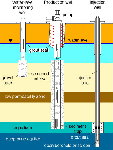
Production and monitoring
For production or sampling of water from wells without open boreholes below the casing, a high permeability connection between the screened interval and the aquifer is required. A coarse gravel pack is normally used. Wells with open boreholes in the production interval exist only in some consolidated rocks in Kansas, such as the Cambro-Ordovician aquifer. After installation, wells are developed and, in some cases, tested. Development is a process of removing the fine particles and drilling fluids left behind by the well construction process; it is often done by pumping, but in some cases can involve the use of air or water pressure or chemical treatment. Simple well tests are often done to determine the sustainable pumping yield (technically known as the specific yield) of the aquifer; however, researchers may also use more sophisticated pump tests and other measurements to better understand the geologic and hydrologic characteristics of the aquifer.
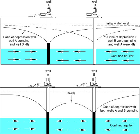
Over short periods, the amount of water that can be extracted from a well is determined by the permeability and thickness of the aquifer, the length of the screened or open interval, and the diameter of the well. Monitoring wells are commonly 2-6 inches in diameter, while large-capacity wells may be several feet in diameter. When a well is pumped, the withdrawal of water results in a local decline (drawdown) of the water table in the vicinity of the well. Figure 18 shows a cone of depression (also called a zone of influence) for well and aquifer characteristics common to western and south-central Kansas. If the saturated thickness above the pump is too small for the pumping capacity, the well can be temporarily pumped dry, and the water table must be allowed to recover. Where pumping wells are close together, their zones of influence may overlap and result in a combined lowering of the water table (Figure 19).
Figure 18--When a well is pumped, the ground-water level near the well forms a cone of depression, as shown by the solid line in this figure.
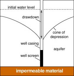
Figure 19--When two nearby wells are pumping, they each create a cone of depression, which overlap to form complicated patterns of ground-water elevation.
When withdrawal has been small compared to the total aquifer storage, the water table will recover to approximately its original level when the well is shut off for some time. In the case of high-capacity irrigation wells in the High Plains aquifer, for example, up to six months after the end of pumping may be required for water-table recovery (Figure 20). Figure 21 shows the pattern of drawdown and recovery in monitoring wells located in an area of Stafford County subject to high irrigation pumping.
Figure 20--After pumping in a well stops, the water level slowly recovers its previous level and the cone of depression disappears.
Figure 21--Water levels (heads) change in various parts of an aquifer system in response to both pumping and natural variations. These figures show the variation in head at two sites in Stafford County. Line 1 in each case is from a well in the bedrock (a brine-containing Permian aquifer). Line 2 is from the lower part of the Great Bend Prairie aquifer, and line 3 is from the upper regions of the aquifer.
When ground-water withdrawals exceed recharge for protracted periods over large areas, systematic declines of the water table occur. This is the case over much of western and some of south-central Kansas, as is demonstrated in the maps shown in Figure 22 and the hydrographs shown in Figure 23. If large areas experience water-table declines, wells do not recover when local pumping ceases, because it may take decades or centuries for water to flow from the fringes of the depression to the center even if an adequate source is available. Such declines can interfere with water supply either by drying up the wells or by lowering the water table to depths that make the water uneconomical for agricultural use because of the cost of pumping.
Figure 22A--Changes in elevation of ground water in the High Plains aquifer, shown in feet, from predevelopment to January 1989.
Figure 22B--Changes in saturated thickness in the High Plains aquifer, from predevelopment to January 1989, displayed as a percentage of decline in the saturated thickness. Because some areas are underlain by thicker aquifers than other areas, this figure provides a reflection of ground-water depletion. For example, a decline of 10 feet (3 m) in an area with an original saturated thickness of 100 feet (30 m) would yield a decline of 10%.
Figure 23--Hydrographs for four representative wells in western Kansas. Hydrographs show the depth-to-water plotted over time.
Injection
Underground injection is the process of using wells to dispose of fluids by pumping them into aquifers. This technique is used to dispose of brines produced along with the recovery of oil, as well as some fluid wastes from municipalities, industry, and manufacturing. This process has been a waste-disposal practice in Kansas at least since the early 1930s when the Kansas State Board of Health began issuing permits to oil companies for the disposal of brines produced along with oil. Since then underground injection has been used to dispose of some industrial fluid wastes where other alternatives are not feasible. Nationwide, interest in underground injection of hazardous and other industrial fluid wastes increased in the late 1960s and 1970s as federal water-pollution control regulations became more stringent. In other parts of the world, underground injection techniques also are used for artificial recharge, remediation of contaminated aquifers, and prevention of saltwater intrusion.
Before installing an injection well, a suitable aquifer must be identified. This aquifer should be able to contain the disposed fluids in the subsurface and keep them away from sources of freshwater. Regulatory agencies use the following criteria to identify suitable zones for underground injection in Kansas: 1) the presence of thick confining units above the rock formations into which the waste will be injected; 2) the presence of simple geologic structure, free of faulted and fractured zones that might allow the disposed fluids to migrate; 3) saltwater must be present in the aquifer; 4) low seismic risk; 5) negligible or low ground-water flow rates in the injection zone; and 6) a long ground-water flow path to areas of ground-water discharge. The most commonly used zones for underground injection of oil brines and wastewaters in Kansas are saltwater aquifers in the Arbuckle Group, Mississippian strata, the Lansing and Kansas City Groups, and the Cedar Hills Sandstone. These zones fit most or all of the criteria for a suitable underground-injection horizon listed above.
When suitable zones for underground injection have been identified and it has been established that underground injection is feasible, a well is constructed and tested (Figure 24). The geologic and engineering characteristics of particular importance are those relating to the engineering performance of the well and the protection of the environment and the public. For example, one important consideration is the nature and thickness of the disposal zone and confining units in the vicinity of the injection well. Another consideration is the compatibility of the native water chemistry with that of the injected fluids to prevent clogging of or adverse chemical reactions in the injection zone. Once the well has been constructed, tests are made on the integrity of the casing, tubing, and cement used in construction and the condition of the wellbore. These tests, which demonstrate the mechanical integrity of the installation, also are made periodically during the life of the well. Other methods also are used to monitor the safety and performance of the injection well, including periodic measurement of injection pressures at the wellhead and in the annular space.
Figure 24--A schematic representation of an injection well.
Another design feature for environmental protection in injection wells (and also monitoring wells that penetrate zones of unusable water) is a grout seal at the impermeable zones separating brine aquifers from overlying usable water-bearing formations. A separate injection tube isolated within the casing permits operators to monitor for fluid in the casing, which indicates when either the casing or the injection tube has failed and must be repaired or replaced.
Kansas has maintained an active program to regulate underground-injection practices since the 1930s and is currently managing a federally mandated program of underground-injection control in the state through provisions of the Federal Water Pollution Control Act Amendments of 1972 and the Safe Drinking Water Act. The intent of this regulatory framework is the controlled emplacement of fluid wastes in the subsurface so that freshwater sources are protected from contamination. Underground injection is currently regulated by the Kansas Corporation Commission (disposal of produced oil brines) and the Kansas Department of Health and Environment (disposal of hazardous and industrial fluid wastes) with oversight from the U.S. Environmental Protection Agency.
Prev Page--Quality || Next Page--Management
Kansas Geological Survey, Kansas Ground Water
Comments to webadmin@kgs.ku.edu
Web version Jan. 2005. Original publication date August 1993.
URL=http://www.kgs.ku.edu/Publications/Bulletins/ED10/06_wells.html