Previous--Northwestern Franklin, Southeastern Douglas, and Osage Counties || Next--Minneola Complex, Ford and Clark Counties
Murfin Drilling Co.
This article available as an Acrobat PDF file (9 Mb).
The Lippelmann field is located in the east-central portion of Decatur County, Kansas. The initial test, the Murfin Drilling Company #1-16 Lippelmann, was drilled in August 1982. Development drilling began immediately after the discovery well, and the field was developed by September 1984. A total of five successful oil wells have been drilled in the Lippelmann field with production coming from the Pennsylvanian Oread, Lansing, and Pawnee-Cherokee formations. Production has been approximately 356,166 BO as of June 1992, with the ultimate recovery projected at 554,732 BO.
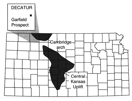
In Decatur County, Pennsylvanian oil is trapped in structures along the southern extension of the Cambridge arch (fig. 1). The Cambridge Arch is located in Norton and Decatur counties and covers only about 1,000 mi2 (2,589 km2) in western Kansas. It is a large, northwest-trending anticlinal feature that extends northward into Nebraska and is separated by a structural saddle from the Central Kansas uplift to the southeast. Structural movement occurred along the Cambridge Arch in pre-Mississippian, preDesmoinesian post-Mississippian, and Mesozoic time.
Figure 1--Location of Garfield prospect, Lippelman field, Decatur County, Kansas.
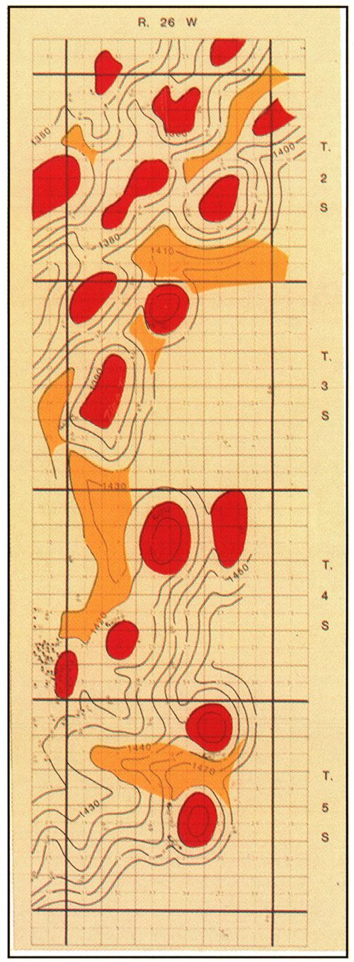
The Garfield prospect was originated in a general geological evaluation of R. 26 W. from T. 2 S. to T. 5 S. done in August 1980 (fig. 2). The original evaluations were done by mapping the Lansing structure and the Anyhdrite to Lansing isopach. Several areas of interest were identified due to holes with shows of hydrocarbon and structural and isopach mapping which indicated a test could be drilled in a more favorable position with the aid of seismic information.
Figure 2A--Lansing structure.
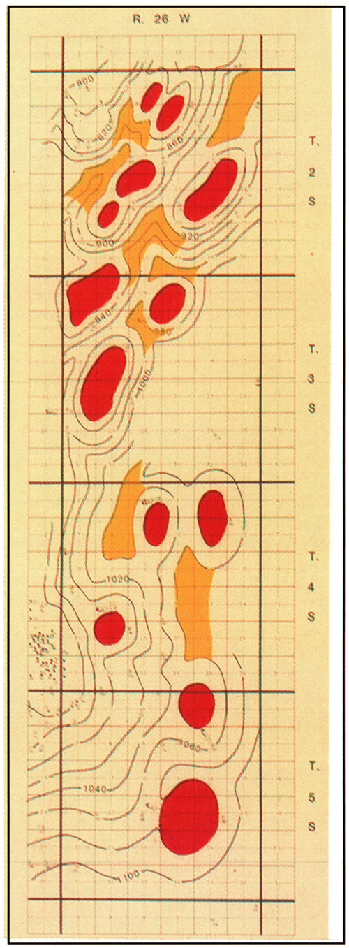
Figure 2B--Anhydrite to Lansing isopach, 7/24/1980.
Several prospects in T. 3 S. were of the quality to have acreage checks performed. The first was located around secs. 5 and 6 due to a possible structural anomaly set up by holes in sec. 32, sec. 5, sec. 6, sec. 12, and sec. 7. Another was located in secs. 3, 4, 9, and 10 generated by a well in sec. 9 with a slight show in the Lansing-Kansas City.
The third prospect, the Garfield prospect, was built on a test that recovered free oil from the Lansing in sec. 19 and an anomalously high hole in sec. 17, resulting in a prospect in secs. 17, 18, 19, and 20.
On the Garfield prospect, Murfin Drilling Company obtained acreage in secs. 19, 20, and 29, and we also obtained all of sec. 16, which was not part of the original geological ideal. The dry hole in the NE NE NE sec. 17 was the only control point for our lead and had only show of gas in the upper Lansing. The hole was drilled by Consolidated Oil and Gas and John O. Farmer in 1970, with three DST's. The DST in the upper Lansing had 480 ft (146 m) of gas in the pipe with mud and water and good reservoir pressures. The Lansing was at -949 ft (-289 m) and the Anhydrite to Lansing interval was 1,401 ft (427 m).
The geophysical method used to investigate the prospect was correlation point seismic information. The seismic records were evaluated with an Anhydrite Time Structure map used in conjunction with isochron maps to various reflectors below the anhydrite.
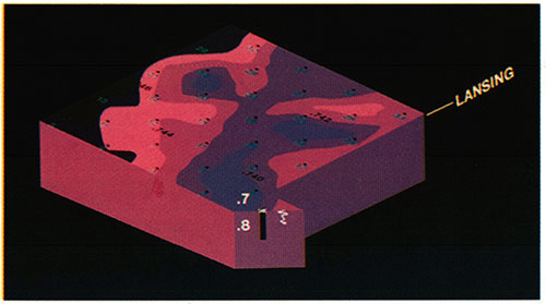
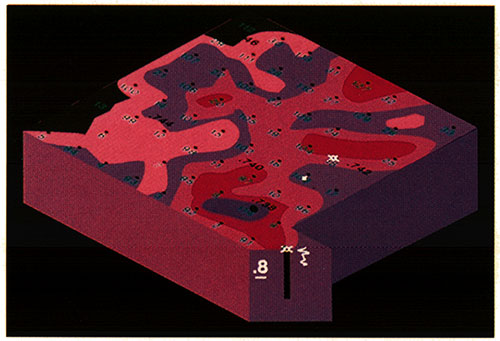
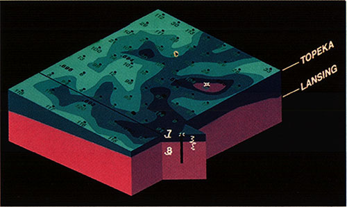
Seismic program was assigned to evaluated sec. 16. This prospect was termed the Garfield prospect, and the acreage to the southwest termed the Tacha prospect. The following discussion will be limited to sec. 16 and the resulting development around the Garfield prospect. Shot points were assigned on a diagonal 20-acre (8-hm2) pattern on sec. 16 and also a shot point on the Consolidated Oil & Gas and J. O. Farmer hole in the NE NE NE sec. 17. The original program on the Garfield prospect consisted of 33 points. The seismic program was shot by Reliance Exploration of Wichita, Kansas, using 180-ft (55-m) shot holes loaded with 5-10 lbs of charge for the "A" shot. A second shot for each hole was recorded at approximately 60 ft (18 m) with 2 1/2lbs of charge. The records were 12 traces, split-spread recorded with a 502-130 filter and computed to a 2,500-ft (762-m) above-sea-level datum. The records were displayed on photographic paper, and no tape records were recorded. The identification of the various horizons was accomplished by using regional velocities since no synthetic seismogram was available in the area. The resulting interpretation is presented in the next four figures. The graphic display of these maps, and all following sets of maps, is a 3D view of sec. 16 as seen from above and from the northwest with the Consolidated Farmer well shown as a bore hole with a synthetic seismogram displayed beside the hole. The synthetic seismogram was generated from the Murfin #1-16 Lippelmann, which was drilled after the original interpretation was completed. Figure 3 shows the shot points as spotted on the surface elevation. The layers indicate the various horizons picked on the correlation points, which include the Topeka and Lansing formations. Figure 4 represents a surface of the anhydrite below a datum of 2,500 ft (762 m) with a 0.005-sec contour interval. A positive feature can be seen on the Anhydrite Time Structure in the northwest portion of sec. 16 around shot points 2, 3, 4, 7, 8, and 11. Figure 5 represents the Topeka surface below the flattened Anhydrite Time Structure. The contour interval is 0.002 sec. As presented in the figure, a thin is seen to include shot points 1, 6, and 8. Figure 6 represents the surface of the Lansing below the flattened anhydrite. The thin in sec. 16, offsetting the well in 17 is somewhat larger. The general trend is a thin running northwest to southeast.
Figure 3--Murfin Drilling Co., Garfield prospect, Decatur County, T. 3 S., R. 36 W.
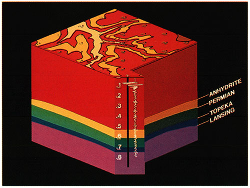
Figure 4--Anhydrite time surface.
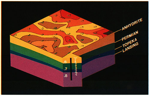
Figure 5--Anhydrite to Topeka time surface.
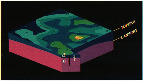
Figure 6--Anhydrite to Lansing time surface.
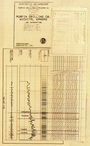
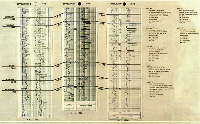
A location was selected at the SE NW NW sec. 16 and the Murfin Drilling Company #1-16 Lippelmann was spudded 8-28-82 and completed as an oil well. The first DST in the Oread recovered 30 ft (9 m) of clean gassy oil, 120 ft (37 m) of mud-cut oil, 400 ft (122 m) of highly oil-cut mud, and 360 ft (110 m) of muddy water (fig. 7).
Figure 7--Synthetic seismogram of Lippelmann #1.
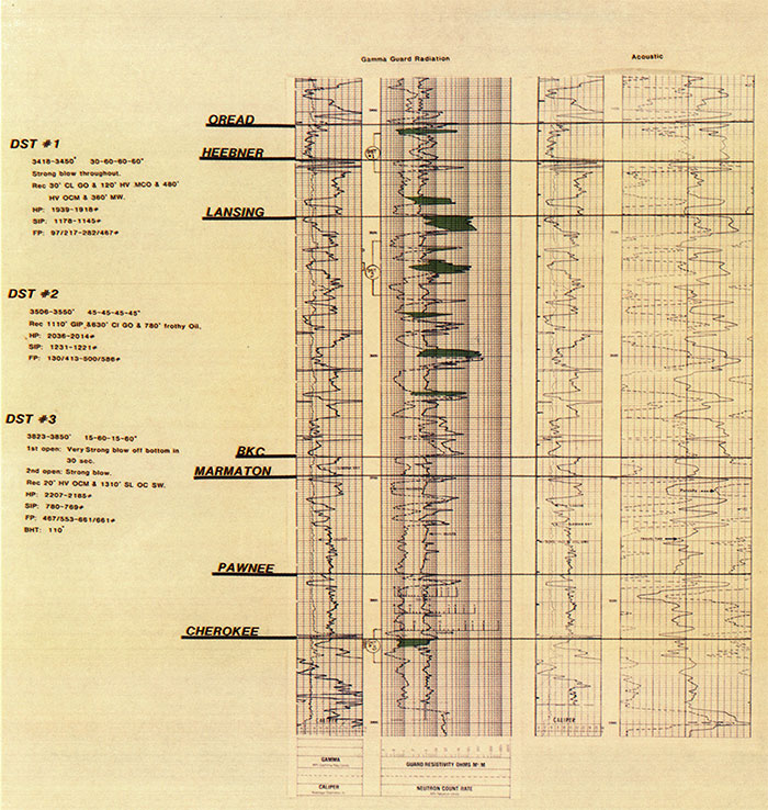
The second DST (3,506-3,550 ft, 1,069-1,082 m; Lansing C, D, and E) recovered 1,100 ft (335 m) of gas in pipe, 630 ft (192 m) of clean gassy oil, and 780 ft (238 m) of frothy oil with good pressures.
The third DST in the Cherokee (3,823-3,850 ft; 1,165-1,173 m) recovered 20 ft (6 m) of heavy oil-cut mud and 1,310 ft (400 m) of slightly oil-cut saltwater.
The Lansing formation was penetrated as a subsea datum of -923 ft (-281 m) and the Anhydrite to Lansing interval at 1,390 ft (424 m), which represents 11 ft (3.4 m) of thinning to the well in sec. 17.
Figure 7 also presents a sample record correlated to a synthetic seismogram generated from the Murfin #1-16 Lippelmann along with the logs from the test and the DST results.
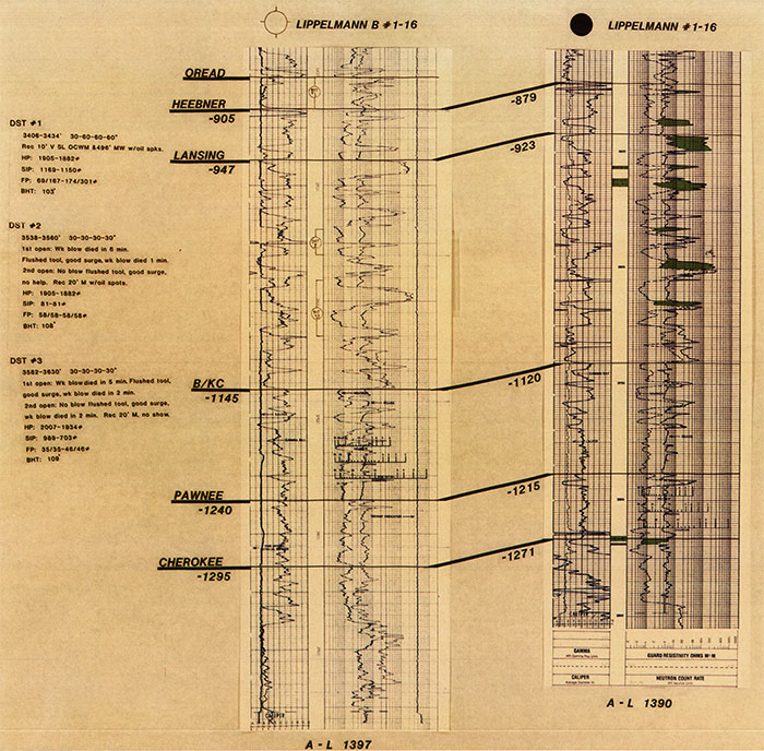
Since the N/2 and the S/2 of sec. 16 were separate leases, it was decided by Murfin Drilling Company to drill the Murfin "B" #1-16 in the south half, located in NE NW SW, just north of shot point # 18. The well was spudded on August 28, 1982, and ran low all the way down to total depth (TD). The hole had a Lansing datum of -947 ft (-289 m) and an Anhydrite to Lansing datum interval of 1,397 ft (426 m) (fig. 8).
Figure 8--Synthetic seismogram of Lippelmann B #1-16 and Lippelmann #1-16.
Three tests were run during the drilling, but no shows of oil or gas were recovered except for some very slightly oil-cut mud out of the Oread.
With our initial success, we felt that the features in the NW sec. 16 needed to be refined with shot points on 10-acre (4-hm2) locations. The new program resulted in 25 more shot points. The second round of shooting put the charge for the "A" shot at approximately 250 ft (76 m) and the "B" shot was detonated at approximately 100 ft (30 m). Charge sizes increased to 15 lbs on the "A" shot and 10 lbs on the "B" shot. The filter setting and geophone layout were consistent with the first round of shooting. The same graphical display as above is presented with the new shot points filled in on 10-acre (4-hm2) spots.
Figure 9 indicates the location of the infill points along with the initial two tests drilled by Murfin Drilling Company. The #1-16 Lippelmann is displayed at shot point 114 and the Murfin "B" 1-16 is displayed between shot points 18 and 103. Figure 10 is a display of the Anhydrite Time Structure indicating a large positive area in the N/2 sec. 16. Figure 11 displays the Topeka structure below a flattened Anhydrite and again shows a positive feature running northwest-southeast across the section. Figure 12 indicates the same structural configuration on top of the Lansing.
Figure 9--Garfield prospect.
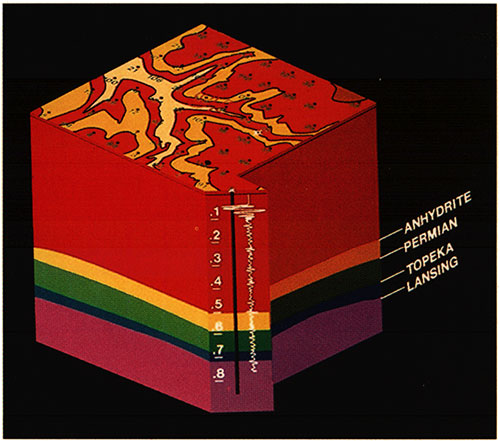
Figure 10--Anhydrite time surface.
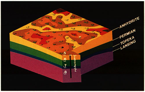
Figure 11--Anhydrite to Topeka time surface.
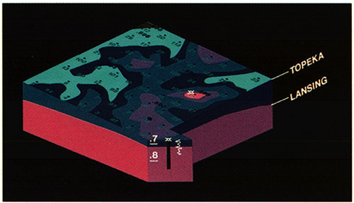
Figure 12--Anhydrite to Lansing time surface.
Shot points in the NW sec. 16 (114, 92, 95, and 97) appeared to be high and thin on all maps. The Murfin Drilling Company #2-16 Lippelmann (shot point #92 NW NE NW) and the #3-16 Lippelmann (shot point #97 NW SE NW) were staked on those shot points.
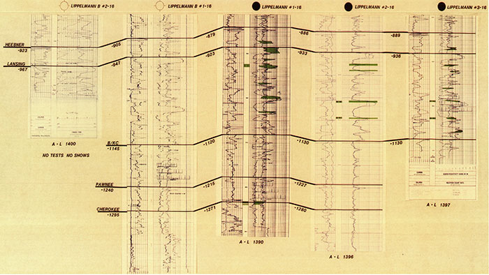
The #2 Lippelmann was spudded on July 28, 1983, and drilled to total depth with seven DST's being performed. Figure 13 shows the resulting log, in cross section form, from the Lippelmann #2-16 and the DST's. The Lansing was penetrated at -933 ft (-284 m) and the Anhydrite to Lansing interval was 1,396 ft (426 m). Pipe was set.
Figure 13--Synthetic seismogram of Lippelmann B #1-16, Lippelmann #1-16, and Lippelmann #2-16.
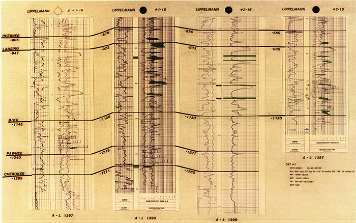
The #3 Lippelmann was spudded on August 7, 1983, and drilled to total depth with one DST (fig. 14). The Lansing was penetrated at -936 ft (-285 m) with an interval of 1,397 ft (426 m).
Figure 14--Synthetic seismogram of Lippelmann B #1-16, Lippelmann #1-16, Lippelmann #2-16, and Lippelmann #3-16.
Murfin Drilling obtained a farm-out from Diamond Shamrock in the S/2 sec. 9 and decided to shoot a diagonal 20-pattern (nine more points) there (figs. 15-18 are a result of that interpretation). The wells which had been drilled previous to the additional shooting are displayed on the maps in figs. 15-18. Murfin Drilling Company had also renewed the lease on the S/2 sec. 16 from Mr. Lippelmann on a six-month term.
Figure 15--Garfield prospect, Decatur County.
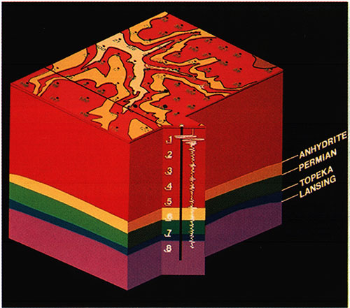
Figure 16--Anhydrite time surface.
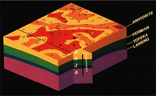
Figure 17--Anhydrite to Lansing time surface.
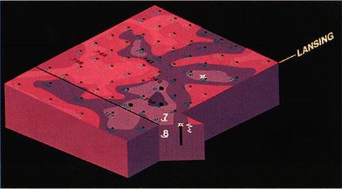
Figure 18--Anhydrite to Topeka time surface.
Because of the resulting interpretation, it was decided to offset to the original three wells somewhere in the SW sec. 9 and also at a possible location on a high thin spot in the S/2 sec. 16. After an evaluation of the interpretation, Murfin Drilling Company decided to drill near the SE SE SW sec. 16 between shot points 27 and 127. This seemed to be on the feature running northwest/southeast and also on a somewhat positive Anhydrite.
The Murfin "B" #2-16 was spudded on November 14, 1983, and drilled to depth with no tests or shows and TD in the Lansing without reaching the base of the Kansas City. The Lansing was at -967 ft (-295 m) and the Anhydrite to Lansing interval was 1,400 ft (427 m). Figure 19 indicates the relationship of the Murfin "B" #2-16 to the wells drilled earlier on the prospect.
Figure 19--Synthetic seismogram of Lippelmann B #2-16, Lippelmann B # 1-16, Lippelmann # 1-16, Lippelmann #2-16, and Lippelmann #3-16.
Several more shot points (5) were now programmed in the S/2 sec. 9 to obtain 10-acre coverage over the area on the proposed 1-9 Shirley. The resulting interpretation as shown in figs. 20-23 located the Murfin #1-9 Shirley on the same diagonal 20 pattern (SE SW SW) north of the #1-16 Lippelmann (at shot point #141). The Murfin #1-9 Shirley was spudded on November 20, 1983. The Lansing was cut at -927 ft (-278 m) and the interval was 1,393 ft (425 m). Pipe was set (fig. 20).
Production from the Lippelmann field through June 1992 has been 249,333 BO from the Lippelmann lease and 106,833 BO from the Shirley lease with the ultimate recovery projected at 429, 873 BO from the Lippelmann lease and 124,859 BO from the Shirley lease.
Figure 20--Garfield prospect, Decatur County.
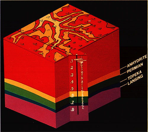
Figure 21--Anhydrite time surface.
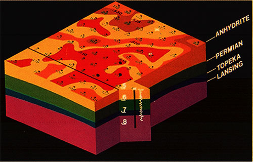
Figure 22--Anhydrite to Topeka time surface.
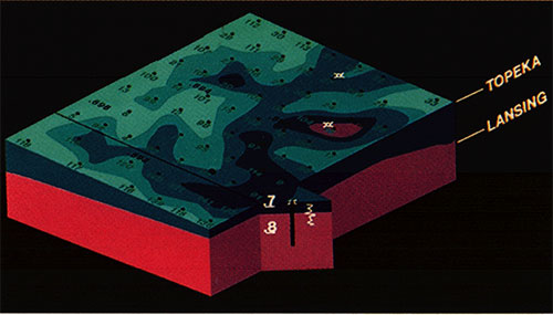
Figure 23--Anhydrite to Lansing time surface.
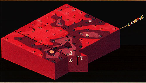
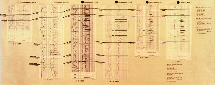
Figure 24--Synthetic seismogram of Lippelmann B #2-16, Lippelmann B #1-16, Lippelmann #1-16, Lippelmann #2-16, Lippelmann #3-16, and Shirley #1-9.
Previous--Northwestern Franklin, Southeastern Douglas, and Osage Counties || Next--Minneola Complex, Ford and Clark Counties
Kansas Geological Survey
Comments to webadmin@kgs.ku.edu
Web version placed online Sept. 4, 2015. Original publication date 1995.
URL=http://www.kgs.ku.edu/Publications/Bulletins/237/Crouch/index.html