![]()
Prev Page--Recharge and Discharge || Next Page--Utilization
Ground Water, continued
Recovery of Ground Water
Springs
In Ford County some water is recovered from springs for domestic and stock use, but the supplies thus obtained are generally small. Small springs are found in the northern part of the county along tributary streams, notably along Duck and Sawlog creeks.
Most of the springs in this area are gravity springs; the water does not issue under artesian pressure but is due to an outcrop of the water table. The water in this type of spring percolates from permeable material or flows from openings in the rock, under the action of gravity, as a surface stream flows down its channel. Gravity springs may be further classified as seepage springs, in which the water percolates from numerous small openings in permeable material; as contact springs, in which water flows to the surface from permeable material over the outcrop of less permeable or impermeable material that retards or prevents the downward percolation of the groundwater and thus deflects it to the surface; and as depression springs, in which water flows to the surface from permeable material simply because the surface extends down to the water table (Meinzer, 1923 b, pp. 50-55). The distinctions between these types of springs are somewhat arbitrary and all may grade into one another.
Most of the springs in Ford County are either contact springs or seepage springs, and issue from permeable beds at or near the base of the Ogallala formation near its contact with the underlying Cretaceous bedrock. In some localities, the bedrock is Graneros shale, and in other areas, notably along Duck creek and along the upper reaches of Sawlog creek, the Ogallala rests directly on the basal members of the Greenhorn limestone. Water is discharged from many springs of this type on both sides of Duck creek near the Ogallala-Greenhorn contact. At some of the seeps there is no visible discharge of water, but the vegetation near the contact is much greener and more luxuriant, indicating that the plants are transpiring groundwater as fast as it is being discharged. Depression springs are found in some parts of the area, particularly at the heads of perennial streams in upland areas, and along the major stream channels.
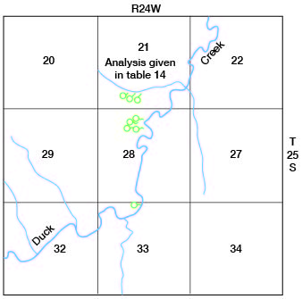
Several small seepage springs are found on sloping hillsides adjacent to some of the streams in the northern part of the county. Some of these springs in the vicinity of Duck creek have been developed and equipped with discharge pipes by the Works Progress Administration. The locations of several of these springs are shown in figure 15. The flow of a typical spring in this area was measured on July 17, 1939, and found to be about one gallon a minute, and an analysis of water from this spring is given in table 14. Some of the springs shown on the map in figure 15 were not visited in the field, but according to reports from local residents, their rates of discharge ranged from less than one gallon a minute to 3 or 4 gallons a minute.
Figure 15--Map showing location of springs along Duck Creek in T. 25 S., R. 24 W., Ford County.
Wells
Principals of Recovery from Wells
In Ford County, groundwater is recovered principally from wells, but some water is recovered also from dug wells and driven wells.
When a well is pumped, there is a difference in head between the water inside the well and the water in the material outside the well. The water table in the vicinity of a pumped well declines and assumes a form comparable to an inverted cone, the apex of which is at the well, as illustrated in figure 14. When a well is discharged under artesian conditions, there is a comparable lowering of the "piezometric surface" - the imaginary surface to which artesian water will rise under its full head. Under artesian conditions the cone of depression exists only as an imaginary cone whose apex is the point of discharge of the well. In any given well the greater the pumping rate the greater will be the drawdown and the greater will be the extent of the cone of depression. Thus, the effects of the discharge will be felt at greater distances from the pumped well; and, if heavy pumping continues, the water levels in wells several hundred feet or even a mile or more distant may be lowered somewhat.
The specific capacity of a well is its rate of yield per unit of drawdown, and is usually stated in gallons a minute, per foot of drawdown. For example, well 37, one of the city wells at Spearville, is reported to yield 50 gallons a minute with a drawdown of about 9 feet. Its specific capacity, therefore, is about 5.5 gallons a minute, per foot of drawdown. Wells in some of the unconsolidated rocks, such as the alluvium of the Arkansas valley, have specific capacities ranging up to 100 gallons a minute per foot of drawdown; whereas, wells in some of the consolidated rooks may yield less than one gallon a minute, per foot of drawdown.
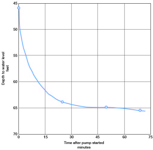
When a well is pumped, the water level drops rapidly at first and then more slowly until conditions of approximate equilibrium are approached, and, in some wells, the water level may continue to decline for several hours or days before approximate equilibrium is established. Drawdown curves of wells 421 and 507 are shown in figures 16 and 17. In determining the specific capacity of a well, therefore, it is important to continue pumping until the water level remains approximately stationary. When pumping stops, the water level rises rapidly at first, but the rate of recovery becomes progressively slower and may continue long after pumping has ceased.
Figure 16--Draw-down curve of well 421, southeast of Ford, Kansas. Well was pumped at rate of 860 to 980 gallons a minute.
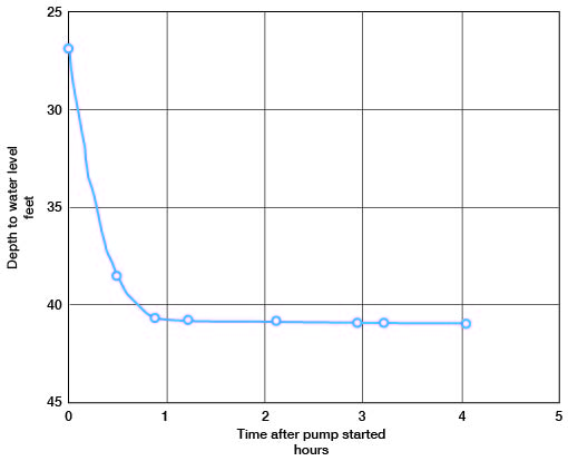
Figure 17--Draw-down curve of well 507, in southwestern Ford County. Well was pumped at rate of 930 to 950 gallons a minute.
Increasing the specific capacity of a well reduces the cost of pumping, as the cost of pumping water increases with the drawdown. The specific capacity of wells sometimes can be increased by modern methods of well construction, some of which are described below under "Drilled Wells."
Methods of Lift
Most of the rural residents in Ford County derive their domestic and stock supplies from wells equipped with hand-operated lift or force pumps, or with pumps operated by windmills, engines, or electric motors. Some of the farms have been equipped with small pneumatic pressure systems in which the water is forced against air pressure into an air-tight tank from which it flows under pressure to any part of the home or farm.
Many of the irrigation wells in the Arkansas valley are equipped with centrifugal pumps. This type of pump is usually mounted in a pit, or sometimes at the land surface, and can be used only where the depth to water level plus the drawdown does not exceed the working suction limit. A few of the deeper wells in the valley and all of the irrigation wells on the south uplands are equipped with deep-well turbine pumps. A series of connected turbines called stages or howls are submerged below the water table (or just above, in some wells) and are connected by a vertical shaft to a pulley or vertical motor at the top. The number of such units varies, depending on the height the water must he forced, but the average installation in irrigation wells in Ford County comprises 3 stages. Most of the pumps used for irrigation are driven by stationary gasoline engines, but a few are electrically driven. Tractors are used to operate some of the pumps.
Many types of power-driven pumps or lifting devices are in use on the industrial and municipal wells of the area. Some of the older installations consist of single- or double-action plunger-type pumps installed in the well, and driven by electricity, steam or internal-combustion engines. Some of the older wells, including well 196, are pumped by air lift. In this method compressed air is forced through a nozzle submerged some distance below the water level and the resulting mixture of water and air is carried to the surface where it is discharged. Where drawdowns are excessive or where the water level is at considerable depth, air lifts of two or three stages are sometimes used. One well (482) is pumped by natural gas, using the same principle as air lift. Most of the industrial and municipal wells in the area are equipped with deep-well turbines driven by electric motors.
A few wells in the county flow at the surface (p. 50) and therefore do not have to be pumped unless larger supplies are needed.
Dug Wells
Of a total of about 530 wells visited in Ford County, 20 were dug wells and 8 were combination dug and drilled wells. Of these 28 wells, 6 were used for irrigation and 10 were out of use. Most dug wells tap rather poor water-bearing material, but because of their large diameter they have a large infiltration area and ample storage capacity. Dug wells generally are more apt to fail during dry seasons and are more subject to contamination than the deeper drilled wells. Dug wells generally are curbed with native rock, brick, or wood, but some are curbed with concrete blocks and a few with tile. Most of the dug wells for domestic use are about 4 feet in diameter, but some dug wells used for public supply range from 4 feet to 10 feet, such as wells 36 and 37 which are used for the public supply at Spearville. Two of the three city wells at Bucklin (467 and 468) are dug wells 7 feet in diameter, one being curbed with brick, the other with rock.
A few dug wells have been listed in the tables of well records as dug and drilled wells, and well 36 at Spearville, well 467 at Bucklin and five of the wells used for irrigation on the uplands south of the Arkansas valley (393, 402, 425, 435, 485) are examples of this type of well. Well 467 was dug 7 feet in diameter to a depth of 111 feet or 8 1/2 feet below the water table, and between the depths of 111 and 125 feet. Most of these irrigation wells were dug and uncased down to about the water level-below which a 15- or 20-inch hole was drilled and cased down into the water-bearing gravel.
Driven Wells
Driven wells can be put down only where the materials are sufficiently permeable and soft enough to permit a pipe being driven and where the depth to water level is within 10 or 15 feet of the surface. Driven wells are used for domestic and stock supplies in some of the valleys containing water-bearing alluvium. They range in diameter from 1 1/4 to 1 1/2 inches and are equipped with a screened drivepoint at the bottom. Most of them are equipped with hand-operated pitcher pumps. Driven wells are likely to fail during dry seasons, but where the thickness of the water-hearing formation is not limited, additional pipe can be added and the screened point can be driven deeper into the formation.
Drilled Wells
Most of the domestic and public supplies and all of the industrial groundwater supplies in Ford County are obtained from drilled wells. Many of the drilled wells used for domestic and stock purposes on the uplands were drilled by portable cable-tool (or solid-tool) rigs. These wells are cased with galvanized-iron or wrought-iron casing, generally 5 5/8 inches in diameter. Those drilled for industrial or municipal use range from 6 to 24 inches in diameter.
Wells in consolidated rocks--A few drilled wells in Ford County obtain water from the consolidated rock formations and are cased through the overlying unconsolidated deposits and several feet into the bedrock. In most of those wells the water enters only at the lower open end of the casing and these are called open-end wells. In some wells, however, the casing extends to the bottom of the hole and the water enters the well through a section of screen or slotted casing placed opposite the water-bearing material. This type of well is usually cased only a short distance into the rock, the lower part of the hole being heft uncased. The yields of drilled wells in the several consolidated deposits in Ford County are discussed on page 120, and the records of all wells visited are given in table 15.
Wells in unconsolidated deposits--Many of the drilled wells, in the upland areas, that obtain water from unconsolidated material (sand or gravel) are cased to the bottom, and receive water only through the open end of the casings.
The efficiency of wells drilled in unconsolidated deposits may be increased in several ways. The intake area may be increased by perforating those portions of the casing opposite the water-bearing beds or by using commercial well screens. In order to know where to perforate the casing and in order to select the openings of the proper size, it is important to know the depth and thickness of the water-bearing beds. While the well is being drilled it is advisable to take samples of the material every few feet. The grain-size of the water-bearing material determines the size of openings to be used in the screen. Where the water-bearing material is fine-grained, a layer of carefully-screened gravel may be placed in the annular space between the well screen and the outside wall of the well. In wells of this type, which are called gravel-packed wells, the effective diameter and intake area of the well is increased and the velocity of the incoming water may he reduced sufficiently to prevent fine material from moving into the well. There are two methods for making gravel-packed wells. In one method the gravel is placed around the casing after the hole is completed; in the other, the gravel is put in at the same time the well is being drilled. In constructing a gravel-wall well by the first method, which is most commonly used in Kansas, a hole of large diameter (48-60 inches) is first drilled and temporarily cased. A well screen or perforated casing of a smaller diameter than the hole (12-25 inches) is then lowered into place and centered opposite the water-bearing beds. Blank casing extends from the screen to the surface. The annular space between the inner and outer casings then is filled with carefully sorted gravel - preferably of a grain-size just slightly larger than the openings in the screen or perforated casing, and also just slightly larger than that of the water-bearing material. The outer casing is then withdrawn in order to uncover the screen and allow the water to flow through the gravel packing from the water-bearing material.
The logs of some of the test holes drilled during the investigation show that in some places the water-bearing materials are sufficiently coarse and well sorted that gravel-packed wells are not required in order to obtain large yields. In such places less expensive wells employing well screens or slotted casings but without gravel packing may be used satisfactorily. In places where the water-bearing materials are fine-grained, however, the gravel-packed wells have several advantages that offset the greater initial cost. The envelope of selected gravel that surrounds the screen increases considerably the effective diameter of the well and, hence, decreases the velocity of the water entering the well. This reduction in velocity prevents the movement of fine sand into the well and increases the production of sand-free water. Owing to the increased effective area offered by this type of construction, the entrance friction of the water is reduced and, hence, the drawdown may be reduced materially, As stated above, a reduction in drawdown, at a given yield, means an increased specific capacity and reduces the cost of pumping.
Assuming that a well of the best possible construction is employed; then the maximum amount of water that can be withdrawn from the well is fixed by nature and nothing more can be done to make the well yield more than the water-bearing material will provide. The problem for the driller, then, is to construct each individual well in such a manner as to obtain the greatest yield with the smallest amount of drawdown that is possible under the existing conditions. For further discussion of gravel-packed wells the reader is referred to a report by Rohwer (1940, p. 62) and another by McCall and Davison (1939 p. 29).
Cased drilled wells containing a separate pipe and cylinder for conducting the water to the surface are the dominant type of domestic and livestock well overmuch of the county; however, tubular wells predominate in a large area in the southeastern quarter of the county. Tubular wells are drilled wells with no separate pump pipe - the casing being used to conduct the water to the surface. Tubular wells range in diameter from 2 to 4 inches and generally a cased with galvanized-iron pipe, at the bottom of which is attached a screened point and a brass-lined cylinder of the same diameter as the pipe. The submerged cylinder is connected with a pump at the surface by rods within the casing. This type of well is less expensive than a drilled well of the regular type. The piston and valve leathers can be repaired by pulling out the pump rods, but the pump cylinder can be repaired only by pulling the well casing. Cased wells have the advantage that the entire pumping equipment can be removed for inspection and repair without danger of caving the well.
Accurate measurements of water level in tubular wells are difficult if not impossible, as the water level in the well generally is held somewhat above the water table by the check valve in the cylinder. In most abandoned tubular wells the bottom check valve remains intact, so that the water level in the well does not represent the true water table. Some tubular wells have been abandoned because the screens at the bottom have become sealed off with incrusting materials. The predominance of tubular wells in the southeastern part of the county made it difficult to obtain enough water-level measurements for the preparation of the water-table contour map, plate 1.
It is probable that larger supplies of water generally could be obtained from unconsolidated material if proper methods of well construction were used. There are surprisingly many examples of poor well construction in Ford County, particularly in the Arkansas valley where many of the small irrigation wells have been constructed by the individual owners with improvised equipment and, as a result, are not very efficient. In several of these wells, homemade screens have been used, ranging from improperly-slotted oil drums to rims of tractor-wheels piled one above the other. After a few years use, some of these screens gradually become clogged, resulting in increased drawdowns and reductions in yield. The cost of pumping water from wells increases with an increase in drawdown; hence, any improvement in the efficiency of a well represents a material saving in operating costs. Some of the factors that influence the cost of pumping water have been summarized by McCall and Davison (1939, p. 29):
"First, the well should be put down through all valuable water-bearing material. Second, the casing used should be properly perforated so as to admit water to the well as rapidly as the surrounding gravel will yield the water. Third, the well should he completely developed so that the water will flow freely into the well. ... Increasing the diameter of the well will decrease the drawdown but little, all else remaining equal. The small saving in lift due to use of a large casing usually will not offset the extra cost of the larger well. It is much better to put a 16-inch casing down through all valuable water-bearing material than to start a 24-inch casing and have to stop short of the desired depth. Increasing the depth of the well will have a greater effect on reducing the drawdown than will increasing the diameter, so long as additional water-bearing formations are encountered.
For a description of different types of pumping plants, the conditions for which each is best adapted, construction methods, and a discussion of construction costs, the reader is referred to a report by Davison (1939).
Prev Page--Recharge and Discharge || Next Page--Utilization
Kansas Geological Survey, Ford County Geohydrology
Web version April 2002. Original publication date Dec. 1942.
Comments to webadmin@kgs.ku.edu
The URL for this page is http://www.kgs.ku.edu/General/Geology/Ford/05_gw5.html