Kansas Geological Survey, Open-File Rept. 93-1
Annual Report, FY92--Page 13 of 20
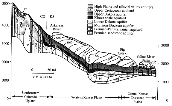
Figure 31--Steady-state distribution in the partially calibrated vertical profile model. Ground-water flow is from regions of higher to regions of lower hydraulic head.

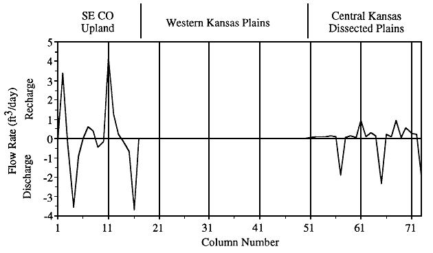
Figure 32--Distribution of recharge and discharge across the upper boundary of the partially calibrated vertical profile model. In the western Kansas plains part of the model only a small amount of recharge, of the order of 10exp-2 to 10exp-3 cubic ft/day per model cell is added.

In the southeastern Colorado upland section of the model the equipotentials are spaced closely together and are vertical in orientation (see Figure 31). This indicates a steep head gradient from the southwest end of the model to the Arkansas River that is controlled by the high regional slope of the land surface. Figure 18 shows an alternation of recharge and discharge across the upper model boundary in this section. The alternation of recharge and discharge suggests laterally adjacent local flow systems, especially in the vicinity of Two Buttes dome. The U.S. Geological Survey 1:100,000 scale, 30 min x 60 min topographic maps of the Springfield and Two Buttes quadrangles show an abundance of springs in the vicinity of Two Buttes. The nearly vertical orientation of the equipotentials near the upper model boundary poorly defines these local flow systems because of the coarseness of the model grid. However, the moderate local relief suggests that the local flow systems are probably shallow in vertical extent (Toth, 1963). Darton (1906) considered most of the valley in the Two Buttes Creek drainage between Two Buttes dome and the Arkansas River as an area where flowing well conditions in the Dakota could be expected. This is consistent with the model results and the interpretation of laterally adjacent local flow systems. Figure 32 shows a small discharge of water from the flow system in columns 9 and 10, near where the Two Buttes Creek intersects the vertical profile. The model also shows the nearby uplands are recharge areas.
Upgradient from the Arkansas River in column 11, more than 4 cubic ft/day (0.1 cubic m3/day) enters the model across the upper boundary (Figure 32). Toward the river the rate of recharge decreases rapidly until column 14, at which point water is discharged from the model at steadily increasing rates until the Arkansas River valley is reached in column 16. This pattern of recharge and discharge suggests that the vertical profile traverses a local flow system involving the south side of the Arkansas River valley and the adjacent upland. Recharge entering this part of the model must cross the Upper Cretaceous aquitard before it enters the upper Dakota aquifer (see Figure 31). The aquitard has a thickness of less than 100 ft (30 m) and has a vertical hydraulic conductivity of approximately 10-5 ft/day.
In the valley predicted steady-state heads are much higher than the elevation of the water table. Head differences in column 16 range from 18 ft (5.5 m) in the upper Dakota aquifer to 134 ft (40.8 m) in the lower Dakota aquifer. Haworth (1913) mentioned flowing wells in the vicinity of Coolidge, Kansas, in the river valley and reported that when the first wells were drilled, the static water level in these wells was approximately 20 ft (6 m) above land surface. Assuming that the water table was about 20 ft below land surface, the static water level elevation in these flowing wells was approximately 40 ft (12 m) above the water table.
Approximately 10 cubic ft/day (0.3 cubic m/day) enters the flow system in the southeastern Colorado upland southwest of the Arkansas River and 6.3 cubic ft/day (0.2 cubic m/day) is discharged to springs and streams locally (Figure 32). The remainder moves on toward the Arkansas River with the subsurface inflow that enters at the southwest end of the model [1.6 cubic ft/day (0.05 cubic m/day)]. The model results indicate that all of the flow in the upper Dakota aquifer in column 16 is discharged to the Arkansas River valley at a rate of 3.7 cubic ft/day (0.1 cubic m/day). Only a small amount is discharged from the upper Dakota aquifer directly beneath the river in comparison with the discharge on the south side of the valley. Most of the flow to the river comes from recharge that passes through a considerable thickness of the Upper Cretaceous aquitard from the north side of the valley before it enters the river or the upper Dakota aquifer.
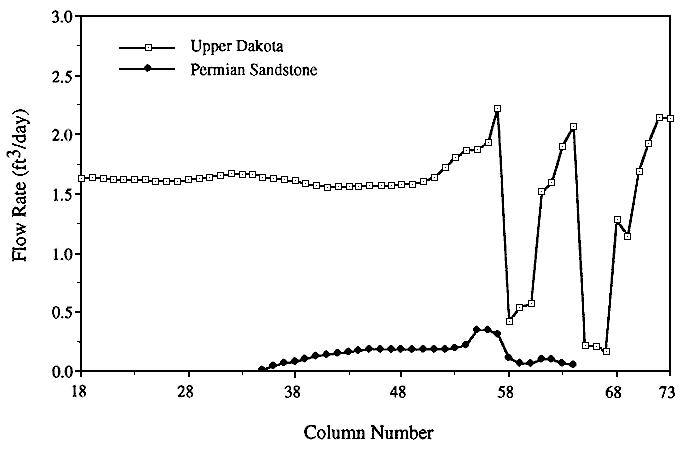
In the western Kansas plains section of the model the intermediate-scale flow system is dominates and ground water is transmitted laterally beyond the Arkansas River to the central Kansas dissected plains section (see Figure 31). The High Plains aquifer is readily recharged by infiltrating precipitation. However, the nearly horizontal orientation of the equipotentials in the underlying Upper Cretaceous aquitard indicates that the flow system beneath the aquitard is hydraulically isolated from the High Plains aquifer. Recharge rates are negligible, of the order of 10-3 cubic ft/day through each of the cells along the upper model boundary, and the total recharge to the flow system is relatively small, approximately 0.15 cubic ft/day (0.004 cubic m/day) (Figure 32). Figure 33 shows that flow through the aquitard to each of the model cells in the upper Dakota aquifer amounts to 0.5% or less of the total cell-by-cell volumetric flow rate (Figure 33). The average cell-by-cell volumetric flow rate in the upper Dakota aquifer in this part of the model is approximately 1.6 cubic ft/day (0.05 cubic m/day) (Figure 34).
Figure 33--Percentage of total cell-by-cell volumetric flow rate in the upper Dakota aquifer that comes from recharge through the Upper Cretaceous aquitard between the Arkansas River and the northeastern end of the partially calibrated steady-state model.

Farther east in the central Kansas dissected plains section of the model local topographic relief is pronounced where the model intersects the Saline River and its tributaries and where the regional slope of the land surface is relatively low. The high local topographic relief and the low regional slope favor local flow system development rather than a continuation of the intermediate-scale flow system into this section of the model from the western Kansas plains (Toth, 1963).
Figure 34--Cell-by-cell volumetric flow rate through the upper Dakota and Permian sandstone aquifers from the Arkansas River to the northeastern end of the model.

The flow patterns indicated by the equipotentials and the pattern of recharge and discharge across the upper model boundary indicate an alternation of gaining and losing streams and recharge to the flow system in the uplands (see Figures 31 and 32). The Saline River and two of its tributaries are gaining streams where they intersect the vertical profile, and two other tributaries are losing streams in their upper reaches. The total recharge to this section of the model is 4.7 cubic ft/day/ft (0.3 cubic m/day/m) and is much lower than the amount in the southeastern Colorado upland. Recharge through the aquitard constitutes up to 100% of the highly variable cell-by-cell volumetric flow rate in the upper Dakota aquifer, but on the average is less than 20% of the total (Figure 33). Discharge to all the streams does not occur in this part of the vertical profile because the aquitard does not allow sufficient recharge to the flow system downgradient of each of the gaining streams. Because of this deficiency, recharge must be supplied to the flow system where the upper reaches of the losing streams have cut down through the aquitard and into the upper Dakota aquifer.
The results of a seepage run indicate a discharge of approximately 1.3 cubic ft/day (0.04 cubic m/day) from the regional flow system to the Saline River (J.B. Gillespie, personal communication, 1993). This rate of discharge is reasonably close to the approximately 1.9 cubic ft/day (0.05 cubic m/day) predicted by the partially calibrated steady-state model when the Upper Cretaceous aquitard vertical hydraulic conductivity is approximately 10-6 ft/day in the vicinity of the river.
Beneath the Saline River, the model predicts flowing well conditions in the upper and lower Dakota and Permian sandstone aquifers. The model results show that heads in the upper Dakota should be approximately 14 ft (4.3 m) higher than the elevation of the water table. Field measurements indicate that the head difference is approximately 8 ft (2.4 m) near the intersection of the vertical profile and the Saline River.
Over most of the lower part of the vertical profile the Permian sandstone
aquifer is separated from the overlying Dakota aquifer by the
Permian-Pennsylvanian aquitard. Significant head differences across
the aquitard indicate that flow is reduced by its presence (see Figure 31).
In Figure 34 the cell-by-cell volumetric flow rate increases steadily to
approximately 0.2 cubic ft/day (0.006 cubic m/day) beneath the
Permian-Pennsylvanian aquitard. Where the aquitard is not present,
the fluctuations in volumetric flow rate suggest that water moves
vertically between the Permian sandstone aquifer and the lower
Dakota aquifer. The local flow system beneath the Saline River
extends downward from the surface and into the Permian sandstone
aquifer (see Figure 31). As a result, flow in the Permian sandstone
aquifer moves upward into the overlying lower Dakota aquifer toward
the river. Downgradient, the volumetric flow rate in the Permian
sandstone aquifer is diminished and ground water from the overlying
lower Dakota moves downward to recharge the aquifer (see Figure 34).
Steady-State Water Budget
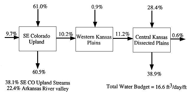
The water budget is summarized in Figure 35 and shows the distribution
of recharge to and discharge from the steady-state flow system for each of
the three model sections. The total flow through the vertical profile is
approximately 16.6 cubic ft/day. (0.47 cubic m/day) This volumetric flow
rate agrees reasonably well with estimates of flow through the Dakota
aquifer made by Helgeson et al. (1993). Helgeson and co-workers
calculated a steady-state water budget of 342 cubic ft/s (9.68 cubic m/s)
or approximately 13.4 cubic ft/day (0.38 cubic m/day) from their model
of the Dakota aquifer system, which covers most of the central Great
Plains, including southeastern Colorado and western and central Kansas.
Figure 35--Total water budget for the steady-state flow system in the vertical profile by model section.

In the southeastern Colorado upland and in the central Kansas dissected plains most of the water that enters the model through the upper boundary is discharged locally and little is contributed to regional flow (Figure 35). Recharge entering the flow system across the water table accounts for 61% of the total water budget, but 60.5% is discharged locally to springs and streams. In the central Kansas dissected plains 28.4% of the total water budget enters the flow system through the Upper Cretaceous aquitard as local recharge, but 38.9% of the total is discharged locally. In contrast, only 0.9% of the total water budget recharges the flow system in the western Kansas plains section of the model. There is no local discharge to surface waters in this part of the flow system.
Recharge to the flow system entering through the Upper Cretaceous aquitard in all three model sections accounts for approximately 30% of the total volumetric flow rate in the model. Belitz (1985) reported that the probable amount of recharge through this confining layer in the Denver basin and adjacent areas to the east is in the range of 15-32% of the total volumetric flow rate through the system. In the vertical profile model more than 97% of the total recharge through the aquitard enters the system in the central Kansas dissected plains and in the southeastern Colorado upland section of the model where the aquitard is thinnest.
The steady-state water budget shows that local flow systems and the vertical hydraulic conductivity of the Upper Cretaceous aquitard heavily influence the water budget in all the model sections. Local flow systems are present in the southeastern Colorado upland and in the central Kansas dissected plains because the local relief and surface drainage systems are sufficiently developed. However, almost twice as much water cycles through the southeastern Colorado upland as through the central Kansas dissected plains. This is because the Upper Cretaceous aquitard's greater extent and lower vertical hydraulic conductivity in the central Kansas dissected plains restrict the flow of water through local flow systems. By comparison, the flow through the western Kansas plains section of the model is sluggish. The low local relief and moderate regional slope of the land surface do not favor local flow system development, and the aquitard has much greater thickness and lower hydraulic conductivity in this part of the model than elsewhere. Thus cross-formational flow characterizes the upper part of the flow system in the southeastern Colorado upland and in the central Kansas dissected plains, whereas lateral flow characterizes the system in the western Kansas plains and in the deeper subsurface in the southeastern Colorado upland.