![]()
Plates
Plate I—A Geologic Section along the south side of the state from Galena to Winfield.
By Geo. I. Adams; to accompany Chapter I.
Scale: Vertical, 1 inch equals 500 feet; horizontal, 1 inch equals 5 miles.
The limestones are represented by the conventional masonry.
The shales and sandstones are left bare.
The surface contours are taken partly from railroad levels and partly from the United States Geological Survey Topographic sheets.
Available as an Acrobat PDF, 3 MB.
Plate II—A Geologic Section extending near the east side of the state along the Kansas City, Fort Scott & Memphis railway from Baxter Springs to Kansas City, and from Kansas City along the west bank of the Missouri river to the north side of the state.
By Haworth and Bennett; to accompany Chapter II.
Scale: Vertical, 1 inch equals 500 feet; horizontal, 1 inch equals 5 miles.
The limestones are represented by the conventional masonry.
The shales and sandstones are left bare.
The surface contours are taken partly from railroad levels and partly from the United States Geological Survey Topographic sheets.
Available as an Acrobat PDF, 4.3 MB.
Plate III—A Geologic Section along the Neosho river from the south line of the state to Council Grove, and along the Cottonwood river from Wyckoff to Cedar Grove.
By M. Z. Kirk; to accompany Chapter III.
Scale: Vertical, 1 inch equals 500 feet; horizontal, 1 inch equals 5 miles.
The limestones are represented by the conventional masonry. The shales and sandstones are left bare.
The contours of this section are principally taken from the United States Geological Survey Topographic sheets, the part along the Cottonwood river being taken from the level of the Atchison, Topeka & Santa Fe railway track.
Available as an Acrobat PDF, 2.3 MB.
Plate IV—A Geologic Section principally along the Missouri Pacific railway from the state line east of Fort Scott to Yates Center.
By John Bennett; to accompany Chapter IV.
Scale: Vertical, 1 inch equals 500 feet; horizontal, 1 inch equals 5 miles.
The limestones are represented by the conventional masonry.
The shales and sandstones are left bare.
The contours are taken from the Missouri Pacific railway track and from the United States Geological Survey Topographic sheets.
Available as an Acrobat PDF, 1.4 MB.
Plate V—A Geologic Section principally along the Osage river from the east line of the state to Alma.
By John G. Hall; to accompany Chapter V.
Scale: Vertical, 1 inch equals 500 feet; horizontal, 1 inch equals 5 miles.
The limestones are represented by the conventional masonry. The Shales and sandstones are left bare.
The contours are almost entirely taken from the United States Geological Survey Topographic sheets.
Available as an Acrobat PDF, 1.5 MB.
Plate VI—A Geologic Section along the Kansas river and the Smoky Hill river from Kansas City to Abilene.
By Bennett and Adams; to accompany Chapter VI.
Scale: Vertical, 1 inch equals 500 feet; horizontal, 1 inch equals 5 miles.
The limestones are represented by the conventional masonry. The shales and sandstones are left bare.
The contours are principally those of the Atchison, Topeka & Santa Fe railway, the Chicago, Rock Island & Pacific railway, and the Union Pacific railway.
Available as an Acrobat PDF, 1.8 MB.
Plate VII—A Geologic Section from Coffeyville to Lawrence along the line of the Atchison, Topeka & Santa Fe railway.
By Erasmus Haworth; to accompany Chapter VII.
Scale: Vertical, 1 inch equals 500 feet; horizontal, 1 inch equals 5 miles.
The limestones are represented by conventional masonry. The shales and sandstones are left bare.
The contours are those of the railroad track.
Available as an Acrobat PDF, 2.1 MB.
Plate VIII—A Geologic Section from Atchison to Barnes, along the Central Branch of the Missouri Pacific railway.
By E. B. Knerr; to accompany Chapter VIII.
Scale: Vertical, 1 inch equals 500 feet; horizontal, 1 inch equals 5 miles.
The limestones are represented by conventional masonry. The shales and sandstones are left bare.
Contours are the levels of the railway track.
Available as an Acrobat PDF, 1.3 MB.
Plate IX—A Topographic Map showing the elevations in the Flint Hills area, copied from the United States Geological Survey Topographic sheets.
By Geo. I. Adams; to accompany Chapter I.
Contour interval 250 feet.
The streams and towns in adjoining territory are given to assist the reader in a proper orientation of the Flint Hills.
Available as an Acrobat PDF, 1.2 MB.
Plate X
Also available as an Acrobat PDF, 1.6 MB.
Figure 1—The Oswego Well.
It represents the two Oswego limestones near the surface with the heavy Cherokee shales for the next 450 feet or more, in which are a number of thin and unimportant limestone beds interstratified with the shale, and also ten or more thin seams of coal. At the base of the well the Mississippian limestone was reached.
Scale: Vertical, 1 inch equals 100 feet. [on original document]
Record obtained through the kindness of Dr. Newlon, of Oswego, Kas.
Figure 2—The Mound Valley Well.
It will be noticed that near the surface three relatively heavy limestone masses occur, below which are the Pleasanton shales and other limestones, the lower ones of which correspond well with the Oswego limestone, as can be seen by a glance at Plate I. Below these we find 427 feet of the Cherokee shales without their base being reached.
Scale: Vertical, 1 inch equals 100 feet. [on original document]
Well drilled by L. C. Crossman, Joplin, Mo.
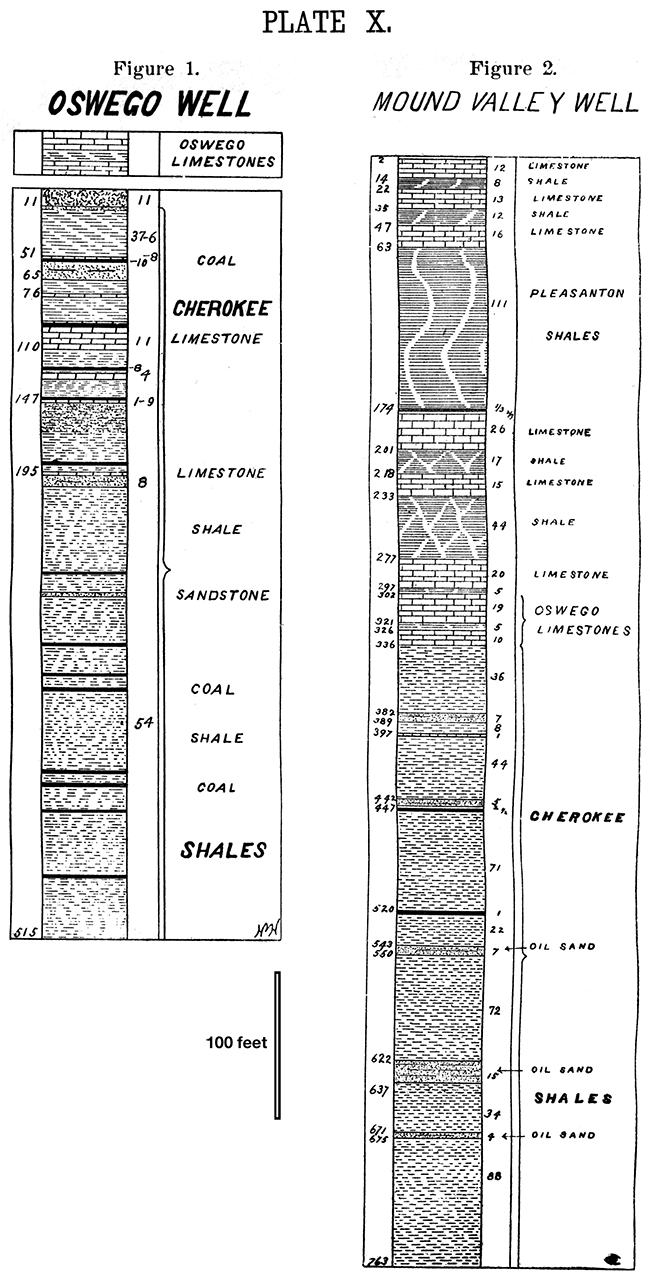
Plate XI Also available as an Acrobat PDF, 2.3 MB.
Figure 1—The Cherryvale Well.
This well was made by a diamond drill which produced a two-inch core, and consequently the record is believed to be unusually accurate, even to the minute details. It will be noticed that the limestones above the Cherokee shales correspond very well with those in the Mound Valley well, Figure 2, Plate X, and that the Cherokee shales are over 400 feet thick, the Mississippian formation being reached at 1,008 feet. The well is located in the southern suburbs of Cherryvale in the angle between the two lines of the Santa Fe railway.
Scale: Vertical, 1 inch equals 100 feet. [on original document]
Well drilled under authority of the city of Cherryvale and record copied from city clerk's books, and afterwards verified by a careful examination of the well core.
Figure 2—The Neodesha Well.
The interesting features of this well are the relatively heavy limestones near the top, being 68, 80, and 50 feet respectively. The depth at which the Mississippian limestone was reached was 1,063 feet. As the well was drilled with the "churn" drill and the sand pump was used only once in five feet, it is quite probable that thin intervening shale beds exist in the heavy limestones above referred to. The Cherokee shales here are over 425 feet thick.
Scale: Vertical, 1 inch equals 100 feet. [on original document]
Well drilled under authority of Guffey & Galey, and record kindly furnished by them.
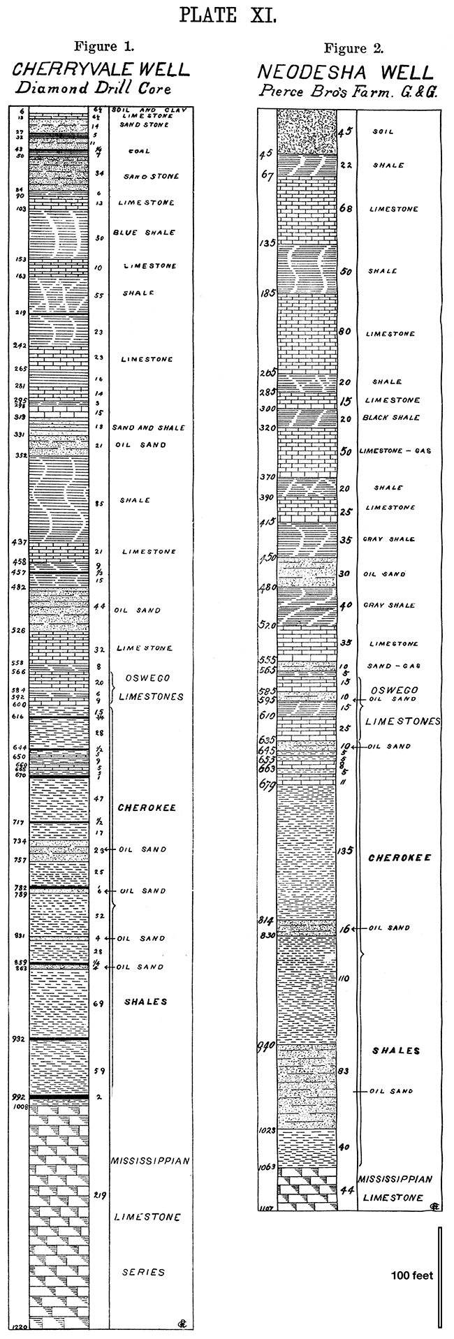
Plate XII
Also available as an Acrobat PDF, 2.3 MB.
Figure 1--The Niotaze Well.
The most interesting and surprising feature of this well is the great thickness of the sandstone, which reaches to a depth of 670 feet, while the first limestone is reached at a depth of 800 feet. This illustrates the existence of the heavy sandstone area lying to the west of Independence and reaching almost to the foot of the Flint Hills. Although the well is 1,158 feet deep it will be noticed that the Cherokee shales were not reached.
Scale: Vertical, 1 inch equals 100 feet. [on original document]
Well drilled under authority of Guffey & Galey, and record kindly furnished by them.
Figure 2--The Fredonia Well.
Beginning near the surface we have a limestone of 110 feet which evidently is the Iola limestone, below which we find the Lane shales and sandstones nearly 160 feet thick, and then the Erie limestone aggregating 172 feet. It is quite probable, however, that thin shale partings exist between the different members of the Erie limestone system. The Pleasanton shales are here 200 feet thick and the Cherokee shales 1327 feet, the Mississippian limestone being reached at 1,170 feet.
Scale: Vertical, 1 inch equals 100 feet. [on original document]
Well drilled under authority of Guffey & Galey, and record kindly furnished by !hem.
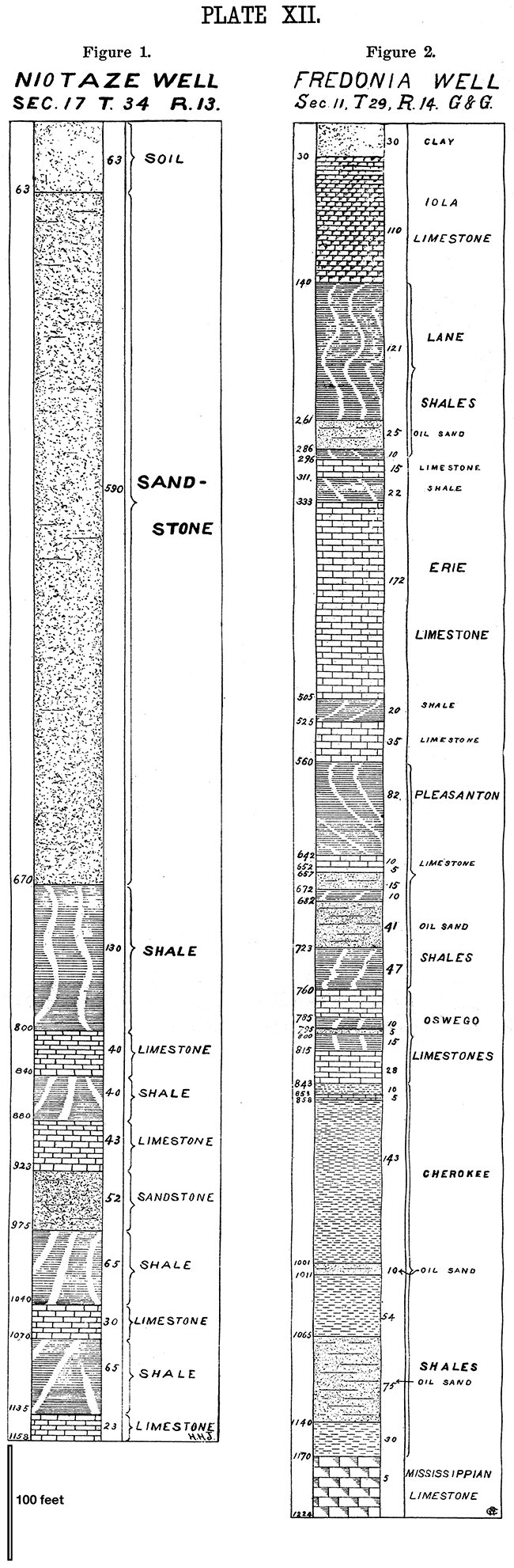
Plate XIII
Also available as an Acrobat PDF, 2.2 MB.
Figure 1—The Fall River Well.
This well is exceedingly interesting on account of its great depth and being so far west. We find near the surface a shale bed 173 feet thick, which doubtless is the Lane shales. Below it we have two heavy limestone beds, one 70 and the other 55 feet thick, one of which is evidently the Iola limestone. But as there is a little doubt in the matter neither one has been labeled as such. Below 530 feet we have 315 feet reported as solid limestone, but it is exceedingly probable thin shale partings intervene. This distance undoubtedly represents the Erie limestone. It is particularly interesting to note that the Cherokee shales here have a thickness of nearly 375 feet.
Scale: Vertical, 1 inch equals 100 feet. [on original document]
Well drilled under authority of Guffey & Galey, and record kindly furnished by them.
Figure 2—The Chanute Well.
The record of this well was not given in sufficient detail near the top to show in just what condition the limestone beds exist. The 98 feet of limestone and shale and the nearly 40 feet of shales below correspond well with the Erie limestone, and the 140-foot shale bed below perhaps represents the Pleasanton shales. The Cherokee shales are here over 420 feet thick.
Scale: Vertical, 1 inch equals 100 feet. [on original document]
Well drilled under authority of Guffey & Galey, and record kindly furnished by them.
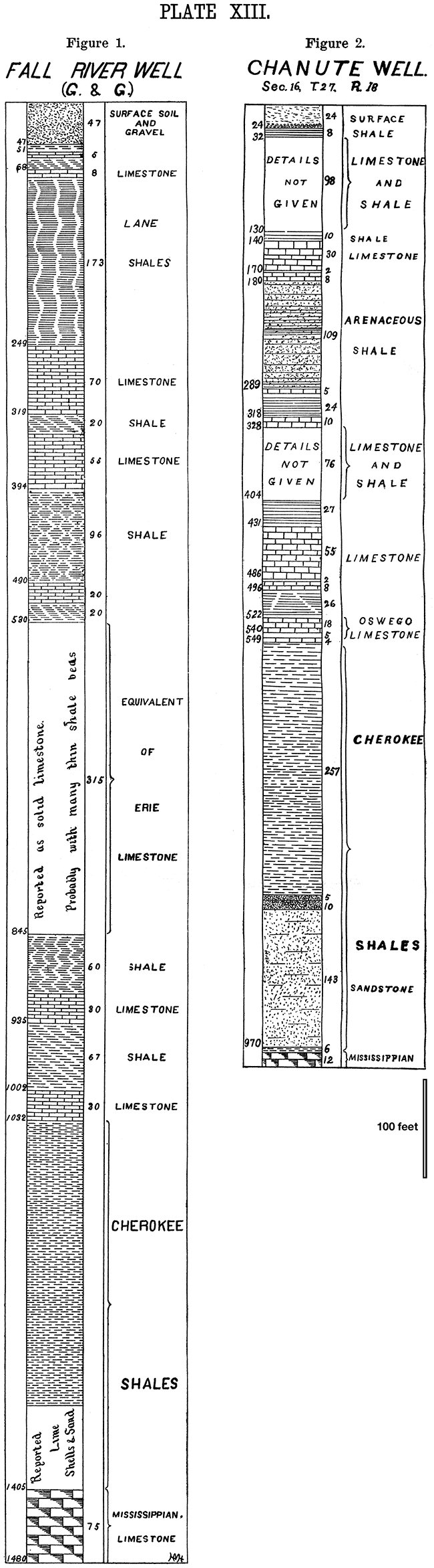
Plate XIV
Also available as an Acrobat PDF, 2.1 MB.
Figure 1—The Humboldt Well.
In this well we have the Iola limestone unmistakably represented, with the Pleasanton shales 187 feet thick, and the Cherokee shales penetrated to a distance of 335 feet without their base being reached.
Scale: Vertical, 1 inch equals 100 feet. [on original document]
Well drilled under authority of Guffey & Galey, and record kindly furnished by them.
Figure 2—The La Harpe Well.
This well is interesting on account of its showing the Iola limestone, the Thayer shales, the Erie limestones, the Pleasanton shales, and the Cherokee shales, each of which is well represented.
Scale: Vertical, 1 inch equals 100 feet. [on original document]
Well drilled under authority of the Palmer Oil Company, and record kindly furnished by Mr. Beatty for the company.
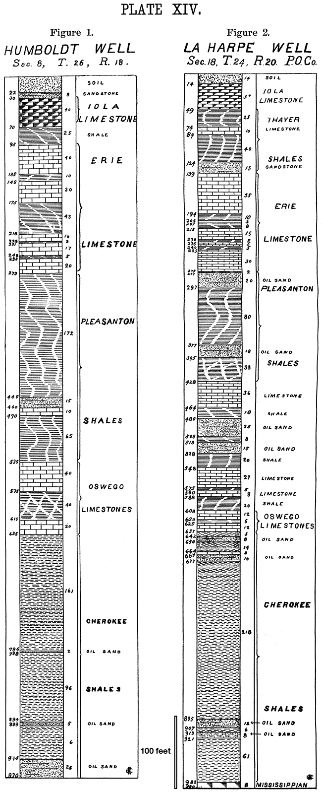
Plate XV
Also available as an Acrobat PDF, 1.7 MB.
Figure 1—The Iola Well.
This represents the record of the old Acers well. As the drill used was a diamond drill and a good core obtained, it is believed the record is unusually trustworthy. It will be noted that in general it corresponds very well with the La Harpe well, the main difference being a smaller amount of limestone and larger amount of shales.
Scale: Vertical, 1 inch equals 100 feet. [on original document]
Figure 2—The Osage Mission Well.
This well likewise was made with a diamond drill and a good core taken out. Its correspondence with other wells in the vicinity, especially the Oswego well, Figure 1, Plate X, will be noted.
Scale: Vertical, 1 inch equals 100 feet. [on original document]
Well drilled under authority of the city of Osage Mission, and record obtained from the city.
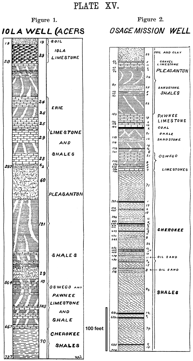
Plate XVI
Also available as an Acrobat PDF, 1.6 MB.
Figure 1--The Mapleton Well.
The main point of. interest in this well record is an unusually heavy bed of shales below the depth of 240 feet. This corresponds with the Pleasanton shales, but it is surprising to find them so thick.
Scale: Vertical, 1, inch equals 100 feet.
Well drilled under authority of Guffey & Galey, and record obtained through their kindness.
Figure 2--The Pleasanton Well.
This well is interesting on account of its showing the existence of the Oswego limestone this far north, and the way the Cherokee shales maintain their thickness, which is here 442 feet.
Scale: Vertical, 1 inch equals 100 feet. [on original document]
Well drilled under authority of Guffey & Galey, and record obtained through their kindness.
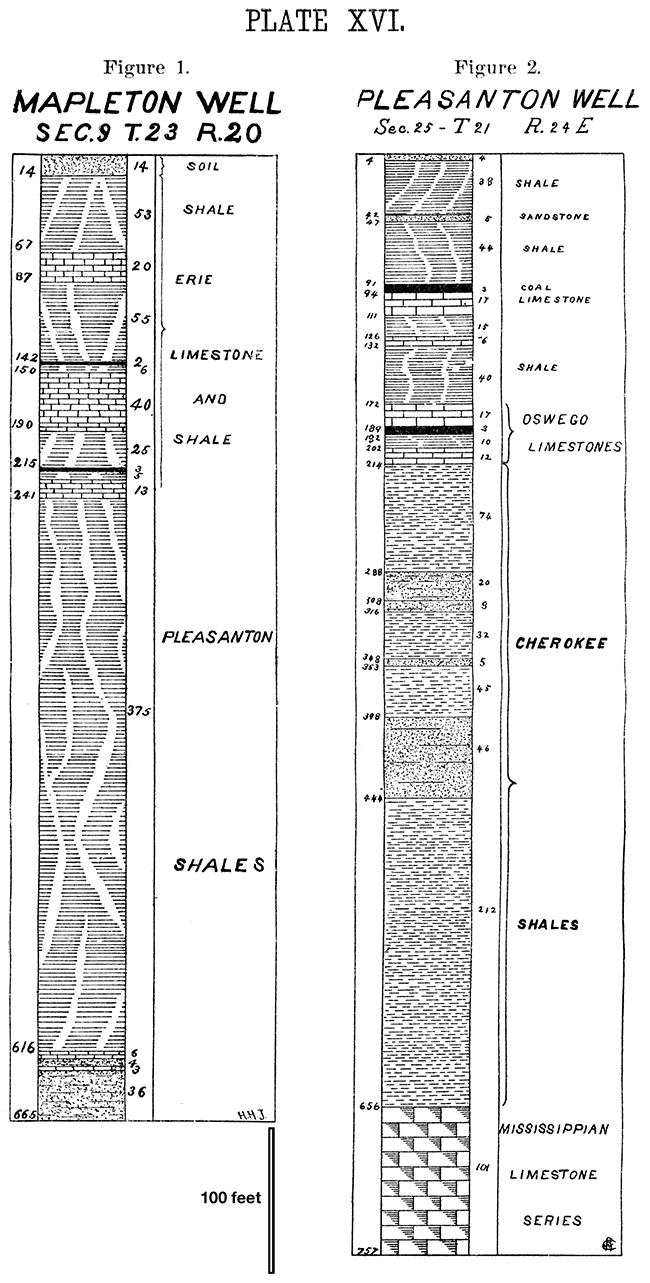
Plate XVII
Also available as an Acrobat PDF, 2.5 MB.
Figure 1—The Paola Well.
This well record is possibly slightly inaccurate although it is not known to be so. The unexpected feature of it is the great depth at which it represents the surface of the Mississippian limestone, 1,038 feet, which makes the Cherokee shales unusually thick, giving them a thickness of over 740 feet.
Scale: Vertical, 1 inch equals 100 feet. [on original document]
Record obtained from Paola city public library.
Figure 2—The Topeka Well.
This well was made with a diamond drill and an excellent core was preserved, so that we may look upon it as being unusually accurate in detail. By comparing it with Plate VI one can readily see that all of the important limestones represented along the Kansas river below Topeka pass westward and are reached by this well. The heavy bed of shales above the Iola limestone doubtless corresponds to the Lane shales, but it was thought best not to be too positive regarding the various correlations; consequently only those of unmistaken identity were correlated, the Iola limestone and the Cherokee shales.
Scale: Vertical, 1 inch equals 100 feet. [on original document]
Record preserved and kindly furnished by Colonel Tweeddale, of Topeka.
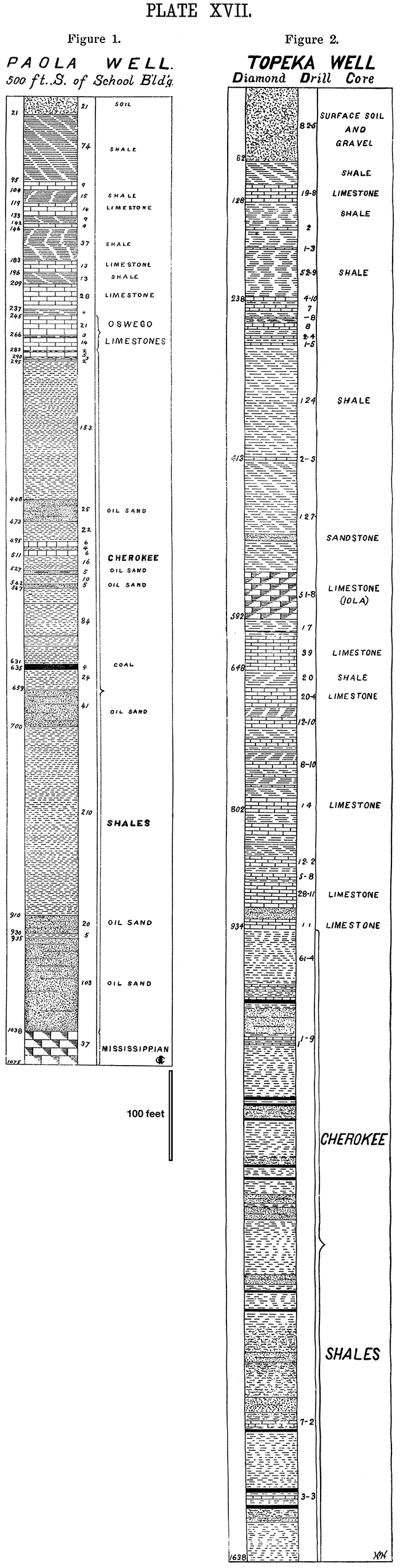
Plate XVIII
Also available as an Acrobat PDF, 1.7 MB.
Figure 1—The Kansas City Well.
The record of this well was copied from Broadhead, Missouri Geological Survey, 1872, Part II, page 86. As it was made with a diamond drill we may assume it is very accurate. It is interesting to note here that the Mississippian was reached at a depth of 715 feet and that the Cherokee shales are over 425 feet thick, and the Pleasanton shales nearly 200 feet thick.
Scale: Vertical, 1 inch equals 100 feet.
Figure 2—The Doniphan Well.
This well is interesting on account of its corresponding so well with the surface conditions along the Missouri river above Kansas City. By reference to Plate II it will be seen that there is a close correspondence between the limestones and shales in this well and those outcropping at the various places along the surface below Doniphan.
Scale: Vertical, 1 inch equals 100 feet. [on original document]
Drilled under authority of the Doniphan Coal and Mining Company, and record kindly furnished by the company.
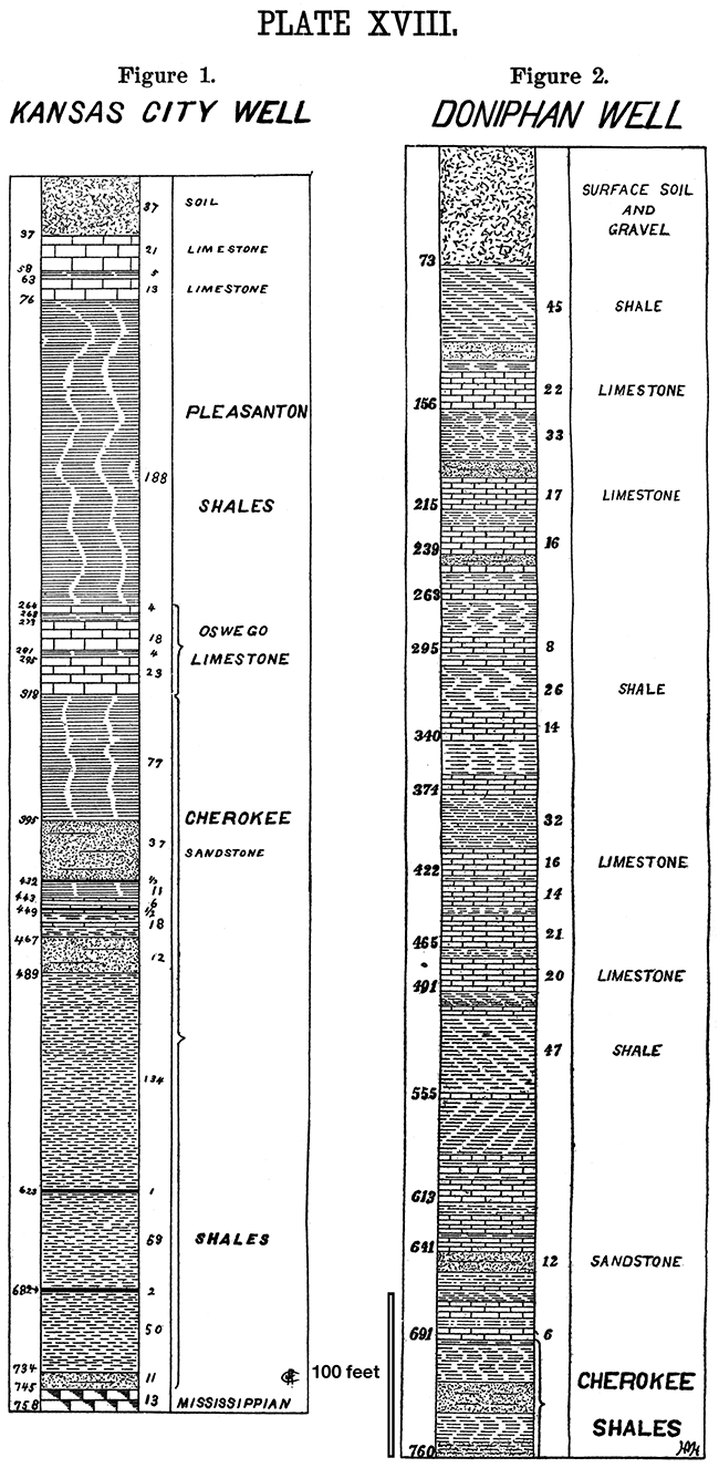
Plate XIX—The McFarland Well.
Also available as an Acrobat PDF, 1.9 MB.
This is a most interesting and instructive well record, as it is located so far to the west and represents so great a depth. Being made with a diamond drill which produced a core three inches in diameter we may place great confidence in the record. It should be noted first that there is an unusually large amount of shale, reaching to a depth of 610 feet. This shows that the various limestones of the upper portion of the Coal Measures do not extend westward as far as otherwise one would have thought. Below the depth of 600 feet, however, the different limestones appear in tolerable order, none of them being as heavy as they are to the east. The conditions to the west along the Kansas river, therefore, are similar to those along the southern part of the state and beyond the Flint Hills, the limestones being replaced by great shale beds, showing that the great limestone producing area of the Carboniferous ocean was located in the eastern part of the state. It is also an interesting record, as it throws so much light on the thickness of the Coal Measures. If it has been rightly interpreted the Cherokee shales were not reached until a depth of 1,832 feet was attained. By comparing this with the Topeka well, which shows a thickness of over 700 feet for the Cherokee shales, one cannot well avoid the conclusion that the base of the Coal Measures here probably is 500 feet below the bottom of the well. As the well is known to have started about 150 feet below the Cottonwood Falls limestone, it shows tolerably conclusively that the Coal Measures flee here more than 2,500 feet thick.
Scale: Vertical, 1 inch equals 100 feet. [on original document]
Well drilled and record furnished by the M. C. Bullock Manufacturing Company, Chicago, Ill.
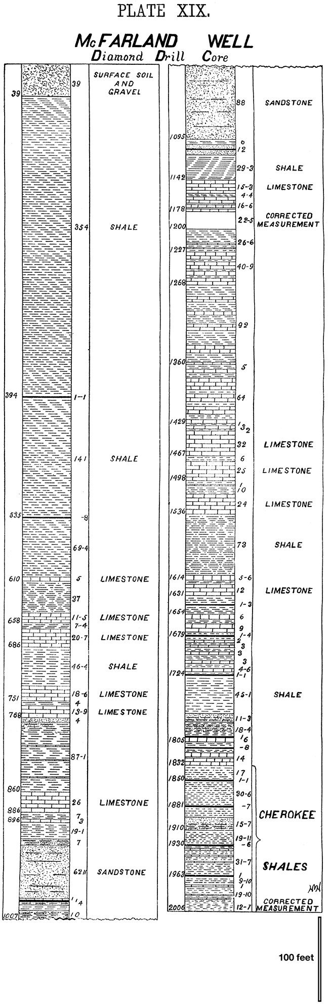
Plate XX—The Leavenworth Well.
Also available as an Acrobat PDF, 2.2 MB.
This well is of considerable interest on account of the light it throws upon the thickness of the Cherokee shales, which are here over 500 feet thick. The upper part of the drawing representing this well is taken from the record of the coal shaft because it was thought that it would be more reliable in detail than any of the drill records. It should be stated, however, that there was a close correspondence between the coal shaft record and the drill record of the well which was used for the lower part of the drawing. The strangest part of this record is 375 feet of hard white sandstone, as mentioned in Chapter II. This has been thought, possibly, to belong to the Mississippian limestone and that the flint rock of the limestone produced the so-called sand.
Scale: Vertical, 1 inch equals 100 feet.
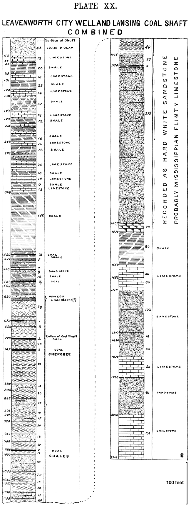
Plate XXI—The Anthony Well.
Also available as an Acrobat PDF, 1.8 MB.
This well record is reproduced here because it has so important a bearing on the westward extension of the Permian along the southern part of the state. The well reaches a total depth of 2,335 feet. It passed through 551 feet of the Red Beds exposed at the surface; then 3D5 feet of blue shales; then 404 feet of the salt beds, reaching the limestone at 1,350 feet. From here to the bottom of the well, nearly a thousand feet, we have an unusually large amount of limestone, which aggregates 684 feet to 301 feet of shales. One cannot correlate the various limestone beds with corresponding beds in the Permian to the east. There can be no doubt, however, but that they are the Permian and Upper Coal Measure limestones. The heavy blue shale beds and salt beds lying above the limestone recall similar conditions, as shown in the McFarland well, where the uppermost members of the Upper Coal Measure limestones seem to be wanting.
Scale: Vertical, 1 inch equals 100 feet.
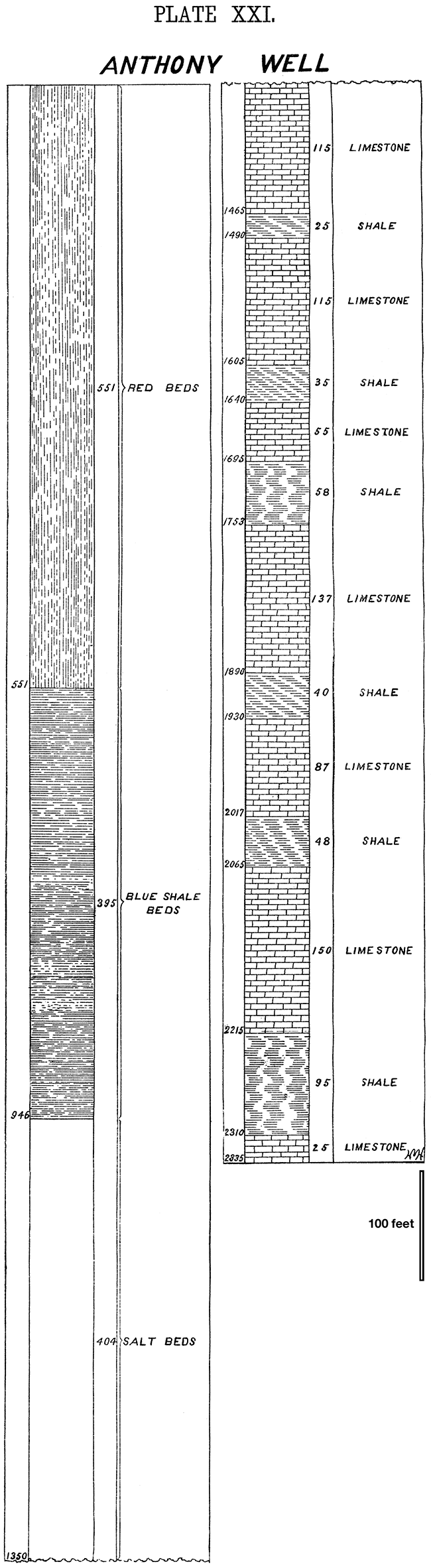
Plate XXII
Also available as an Acrobat PDF, 2.6 MB.
This represents a generalized section of the Carboniferous, from the Mississippian to the top of the Permian. The total depth given is 3,545 feet. In making this estimate it was endeavored to use the mean thickness for the various formations. Had the maximum thickness been used it would have aggregated considerable more.
For further explanation see Chapter IX.
Scale: Vertical, 1 inch equals 100 feet.
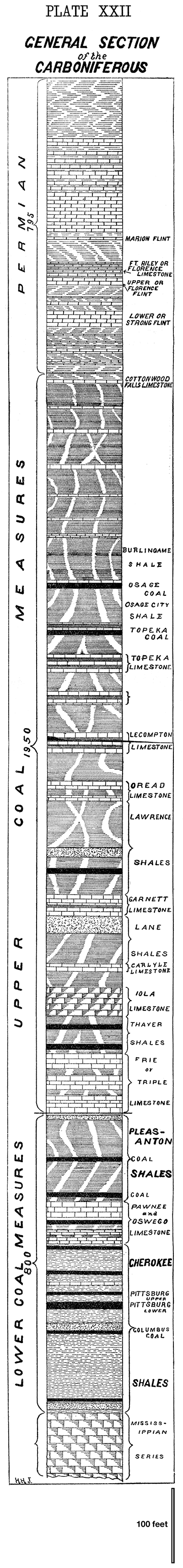
Plate XXIII
To accompany Chapter X.
A mound one mile south of Cherryvale. This represents the process of erosion with a thin limestone bed lying above a heavy shale bed. The limestone is plainly seen at the top of the mound (the Independence limestone), and the perfectly flat top which it has is due to the protection or the limestone cap. The bare places on the sides of the mound are places where the weathering away of the shales is so rapid vegetation cannot get started.
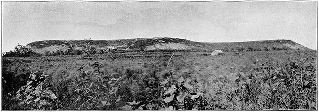
Plate XXIV
To accompany Chapter X.
A portion of the row of mounds one mile north of Cherryvale. The same limestone, the Independence, protects the summit of this mound which was shown in Plate XXI. Here the degradation of the shales on the south side of mound is more rapid than that in Plate XXI, and there is correspondingly a larger portion of the hillside void of vegetation.
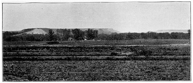
Plate XXV
To accompany Chapter X.
A row of mounds beginning about three miles south of Cherryvale and extending towards Coffeyville four or five miles farther. The summits of these mounds are protected by the Independence limestone, the same one shown in Plates XXI and XXII. Near the left end of the figure one of the mounds is seen plainly standing out by itself, from which the protecting limestone is entirely removed, and which is already beginning to assume the rounded form produced by the weathering of soft materials.
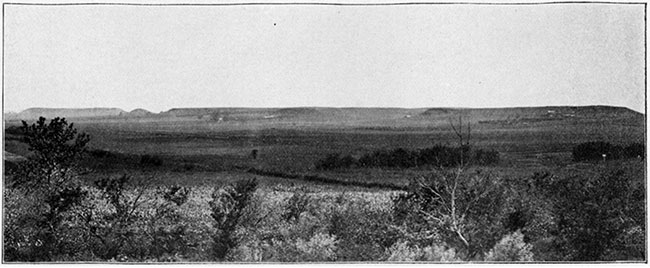
Plate XXVI
To accompany Chapter X.
The southern portion of the bluffs west of Pleasanton. Here we have an escarpment produced by the combined influence of the heavy Pleasanton shales and the bed of Erie limestone lying above which serves as a protection the same as that shown in Plates XXI and XXIII.
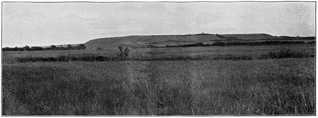
Plate XXVII
To accompany Chapter X.
A scene on the Kansas river, near Lawrence.
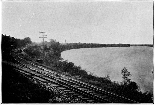
Plate XXVIII
To accompany Chapter X.
Blue Mount, Manhattan. This represents the eastern extremity of the high escarpment just north of the city of Manhattan. The Blue river passes to the right, and the Kansas river on the south. The high bluff is protected by the Cottonwood Falls limestone, as shown at the summit in the left hand part of the figure. This protection has been worn away near the middle of the figure and the valley has begun forming, which in the course of time will cause the right hand portion to become an isolated mound.
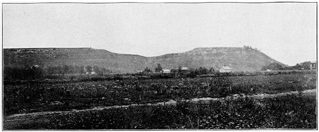
Plate XXIX
To accompany Chapter X.
A scene along the north bank of the Kansas river, about six miles west of Manhattan.
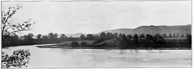
Plate XXX
To accompany Chapter X.
Republican river bluff at Wakefield. This shows the Permian limestone on the bluff on the west bank of the Republican river about one-fourth mile above the village of Wakefield. The stratification of the heavy limestone beds is well represented and the surface soil and gravel above.
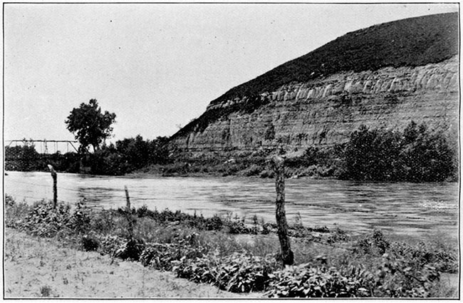
Plate XXXI—A Geologic Map of Kansas (preliminary). By Erasmus Haworth. Available as an Acrobat PDF, 13.8 MB.
The Map is drawn in a semi-perspective manner so as to show the principal features of the stratigraphy along the east and south sides of the state. The evidence upon which such conclusions are based is largely that afforded by the deep wells, some of which are shown on the map. The areal extent of the different geological formations is shown by different styles of shading, all of which is explained in the legend on the margin of the map.
Since the plate was made it has been learned that the boundary line between the Permian and the Dakota in Harvey county should be a few miles nearer Newton.
Scale: Vertical, 1 inch equals 1,600 feet.
Kansas Geological Survey, Geology
Placed on web June 1, 2017; originally published 1896.
Comments to webadmin@kgs.ku.edu
The URL for this page is http://www.kgs.ku.edu/Publications/Bulletins/Vol1/03_plates.html