Kansas Geological Survey, Bulletin 142, pt. 1, originally published in 1960
Originally published in 1960 as Kansas Geological Survey Bulletin 142, pt. 1. This is, in general, the original text as published. The information has not been updated. An Acrobat PDF version (7.2 MB) is also available.
Routine ceramic testing (supplemented by chemical analysis and hot load testing) of samples of refractory clay and silt from the Dakota Formation from 25 locations in Kansas showed that some of the clays can be formed into a good grade of semi-silica refractory brick. The brick exhibit excellent volume stability and hot-load-carrying characteristics at temperatures as high as 2500° F.
It is the purpose of this report to list some areas of refractory clay and silt deposits of the Dakota Formation and to evaluate their adaptability to commercial uses. Clay, in addition to its physical nature, i. e., plasticity, slaking, etc., is generally restricted to particles smaller than 2 microns (Grim, 1953). Silt is the term given to material having a particle size between 2 and 62 microns.
Normally, any material that can be heated slowly to 2570° F. or higher without showing obvious signs of fusion may be classified as a refractory material. Fusion temperature refers to the temperature at which a predetermined shape of the material being tested will deform under its own weight. In addition to having a high fusion temperature, the refractory material must be able to withstand continued exposure to high temperatures, to maintain its shape, to confine heat, to retain its strength, and to resist destruction from both physical and chemical sources at high temperatures, i.e., temperatures above 2000° F.
The manufacture of refractories is a small, relatively unpublicized, but particularly important segment of American industry. Without refractories there would be no heat, light and power, metals, manufacturing, or transportation as we know them today. Virtually every processed material of modern civilization—oil, metals, glass, fabrics, chemicals—owes its existence to the utilization of refractory materials.
The cheapest and most common source of refractory material is clay. Most clays are hydrated silicate of aluminum, commonly formed by leaching of the alkali constituents from feldspathic rocks. Silica (as very fine grained sand or silt) is commonly found associated with the clay in the deposits. The usual clay mineral in a refractory clay is kaolinite. Clays vary in physical properties from hard, rock-like masses to soft, pliable muds.
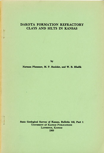
Fire clay is the name given to the clays used in refractory manufacturing. In their natural state they are classified according to their physical characteristics-kaolin, a soft white clay; flint, an extremely hard, rock-like clay; semi-flint, a hard clay but softer than flint; and plastic, a soft, putty-like clay. The white kaolin clay has the highest fusion temperature and the plastic fire clay generally has the lowest fusion temperature. Addition of either silica (SiO2) or alumina (Al2O3) can alter the fusion temperature of the clay. The composition ranges for various types of commercial alumina-silica refractories are plotted on the alumina-silica equilibrium diagram (Fig. 1).
Figure 1—The system SiO2-Al2O3 (after Bowen and Greig, 1924). Compositional ranges for industrial refractories.
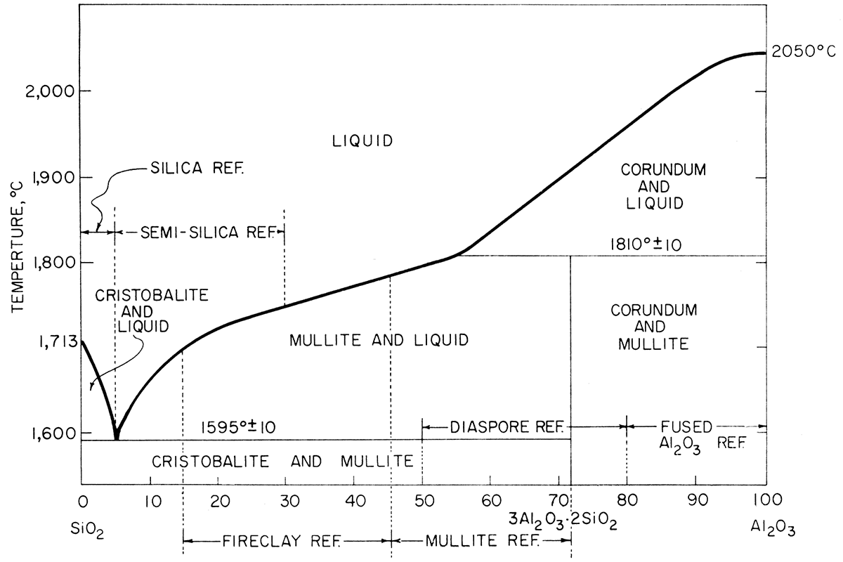
The clays and silts described in this report were sampled from the Dakota Formation, which is the lowest stratigraphic unit of the Gulfian Series of the Cretaceous System in Kansas. Figure 2 shows the location of the major areas in which the Dakota Formation crops out in Kansas. The relation of this formation to the underlying Kiowa Shale and the overlying Graneros Shale is shown in the following stratigraphic sequence:
| Cretaceous System | |||
| Gulfian Series | |||
| Graneros Shale | |||
| Dakota Formation | |||
| Janssen Clay member | |||
| Terra Cotta Clay member | |||
| Comanchean Series | |||
| Kiowa Shale | |||
Figure 2—Map showing extent of Dakota Formation, from which clay and silt samples were taken, in Kansas.
The Dakota Formation is subdivided into the Janssen and Terra Cotta members. The Terra Cotta member, which constitutes two-thirds to four-fifths of the total thickness of the Dakota Formation, consists of massive clay, silt, and sandstone. The outstanding lithological feature of the Terra Cotta member is widespread distribution of gray and red mottled clay. The lower 40 to 50 feet differs distinctly from the upper portion in that it is made up of fairly even, relatively thin beds of clay, silt, sandstone, and lignite. Samples from only the refractory beds containing kaolinite as the predominant clay mineral were used to make test bricks. Various amounts of illite, montmorillonite, and mixed-layer clay minerals are found along with kaolinite in many of the less refractory beds. The lower portion of the Terra Cotta member closely resembles the Janssen member in appearance and coloration. The Janssen member includes beds of lignite, gray to dark-gray clay, silt, and some shale and sandstone (Plummer and Romary, 1942; Moore and others, 1951).
Of the 25 clays and silts discussed in the report, 16 were taken from the Janssen member of the Dakota Formation. Most of the samples came from two beds near the top of the Janssen member. The upper bed is a dark-gray to nearly black clay, which in some localities contains or is overlain by lignite, The lower bed is gray to light gray and thicker than the overlying dark clay. Usable beds of fire clay and buff-firing face brick clays are relatively common in the Janssen member. Three of the four plants manufacturing buff face brick from clay of the Dakota Formation are using one or both of the two beds in the Janssen member mentioned above. The fourth plant is using clay from the lower part of the Terra Cotta member.
Descriptions of measured sections at the locations where the samples were taken are included in the appendix. Bold-face type indicates clay beds from which test bricks were formed. Pyrometric cone equivalents (PCE) also are listed for test-sample sections and some other sections from which test bricks were not formed. The measured-section description not only provides an overall picture of the thickness of the refractory clay section but also provides information on the type and quantity of overburden that must be removed.
The samples are coded as follows: the letter refers to the county, Barton (BT) , Cloud (C), Ellsworth (El) , Lincoln (L), and Ottawa (O); first number refers to a coded sample location; last number refers to layer or bed in the sampled section. When a letter follows the bed number for a clay sample, it means that the sample was a composite of two or more clays. The location, as to section, township, and range, of each sample is given in the appendix.
Samples El-12-2, El-12-4, El-14-9, El-20-W5, El-20-6, and El-72-3 were taken from the lower, more even-bedded part of the Terra Cotta member.
Only three samples, C-27-8, C-30-5, and El-72-14, were taken from the upper portion of the Terra Cotta member. The pyrometric cone equivalent (PCE) of the upper Terra Cotta clays is high, although samples C-30-5 and El-72-14 contain red-mottled clay. It is possible that a large reserve of refractory clays has been overlooked in the upper part of the Terra Cotta member because of red discoloration and because exposures of the clays are relatively scarce. The refractory clay occurs above and below thicker beds of red-firing clays. Neither type of clay is resistant to erosion, therefore exposures are easily covered by eroded red-firing clay material or eroded top soil. The Janssen member and the lower part of the Terra Cotta, on the other hand, are better exposed because resistant sandstone or siltstone beds form protective benches above the clay beds.
The clay samples studied were obtained by channeling on the face of pits excavated for the specific purpose of clay sampling (Plummer and Romary, 1947). The samples, most weighing 100 pounds, were free from surface contamination and weathering.
From each 100-pound sample, 5-pound samples were selected at random and used for chemical analysis, pyrometric cone equivalent tests, and differential thermal analysis. The remainder of the material was divided into two halves; one half was calcined, and the other half was dry-ground for future use.
After the clay samples were collected, pyrometric cone equivalent tests, chemical analyses, and differential thermal analyses were performed to determine whether full-scale ceramic tests were warranted. The pyrometric cone equivalent test evaluates approximate fusion temperature of the clay. Chemical analyses provides information on the ratio of refractory oxides to fluxing oxides. Differential thermal analysis tells what clay minerals are present and yields some information on the oxidation behavior of the clay during firing.
The PCE or pyrometric cone equivalent of a clay is determined by comparing its softening or fusion point with that of standard pyrometric cones, which are small tetrahedrons having standardized oxide compositions. When heated at a specified rate, the standard cones partly fuse, causing the tip to bend toward the base and finally touch it. The clay to be tested is formed into cones of the same size and shape as the standard pyrometric cones. The clay cones are mounted alternately with standard cones on a circular refractory plaque and heated at a specified rate until both the clay cone and known cone bend over and touch the refractory plaque. Tests were conducted in a gas-fired furnace designed for this specific purpose by the American Refractories Institute, and were in accordance with A.S.T.M. Standard C24-56 (adopted in 1920; revised in 1956).
The PCE's of the various classes of fire clay refractories have been designated by the American Society for Testing Materials (C-27-58T) and are given in Table 1. Several changes have been introduced in the latest revision. The PCE value for low duty firebrick has been lowered from cone 19 to cone 15. No PEC is specified for semi-silica refratory brick, but rather the brick is classified according to silica content and percent hot load subsidence test. The pyrometric cone equivalents of the Kansas refractory clays are listed in Table 2. Several meet the PCE specifications for medium duty firebricks, i. e., cone 29 or higher.
Table 1—Fire clay refractory brick classification according to ASTM Designation C27-58T.
| Class | Type | Pyrometric cone equivalent (min.) |
Panel spalling loss, max. % |
Hot load subsidence, max. % |
Reheat shrinkage, max, % |
Modulus of rupture, min. psi. |
Other test requirements |
|---|---|---|---|---|---|---|---|
| Super duty | Regular | 33 | 8 at 3000° F. | 1.0 at 2910° F. | 600 | ||
| Spall resistant | 33 | 4 at 3000° F. | 1.0 at 2910° F. | 600 | |||
| Slag resistant | 33 | 1000 | Bulk density, min. 140 lb. per cu. ft. | ||||
| High duty | Regular | 31 1/2 | |||||
| Spall resistant | 31 1/2 | 10 at 2910° F. | 500 | ||||
| Slag resistant | 31 1/2 | 1200 | Bulk density, min. 137 lb. per cu. ft. or max. porosity 15 percent |
||||
| Semi-silica | * | 1.5 at 2460° F. | 300 | Silica content min. 72 percent | |||
| Medium duty | 29 | 500 | |||||
| Low duty | 15 | 600 | |||||
| * Denotes no ASTM specification for property for particular brick. Individual users may have minimum specifications. | |||||||
Table 2—Pyrometric cone equivalent of Kansas refractory clays.
| Sample | PCE | Sample | PCE | |
|---|---|---|---|---|
| C-27-8 | 27-28 | El-45-7 | 30 | |
| C-30-5 | 31-32 | El-57-A | 28-29 | |
| C-35-6 | 30 | El-60-6 | 28-29 | |
| BT-3 | 23 | El-60-7 | 29 | |
| L-39-2 | 28 | El-60-13 | 28 | |
| O-5-6 | 30 | El-60-B | 28-29 | |
| El-12-2 | 31-32 | El-72-3 | 28-29 | |
| El-12-4 | 31-32 | El-72-14 | 27 | |
| El-14-9 | 26 | El-73-C | 27 | |
| El-20-W5 | 26 | El-85-C | 28 | |
| El-20-6 | 28-29 | El-85-11 | 28-29 | |
| El-29-4 | 30 | El-87-10 | 23-26 | |
| El-29-10 | 31 | El-105-4 | 27 | |
| El-45-3 | 29-30 |
Differential thermal analysis determines the temperature relationship of an unknown material to a reference material when both materials are heated at the same constant rate. The unknown material has three possible temperature relationships to the reference material at any particular time during the heating period.
The way in which various materials react when heated has been observed and recorded. An unknown material is identified by comparing its thermal response pattern with those of known materials.
Two recent publications (Smothers and Chiang, 1958; Mackenzie, 1957) adequately review differential thermal analysis equipment and methods. The apparatus used in the Geological Survey laboratory included a Leeds and Northrup Model "S" Micromax recorder operating in conjunction with a d.c. amplifier, an L. and N. controller, timer, and Variac transformer, by which the temperature of the furnace was increased at a uniform rate of 10°C per minute. Samples were heated in an alumina ceramic holder.
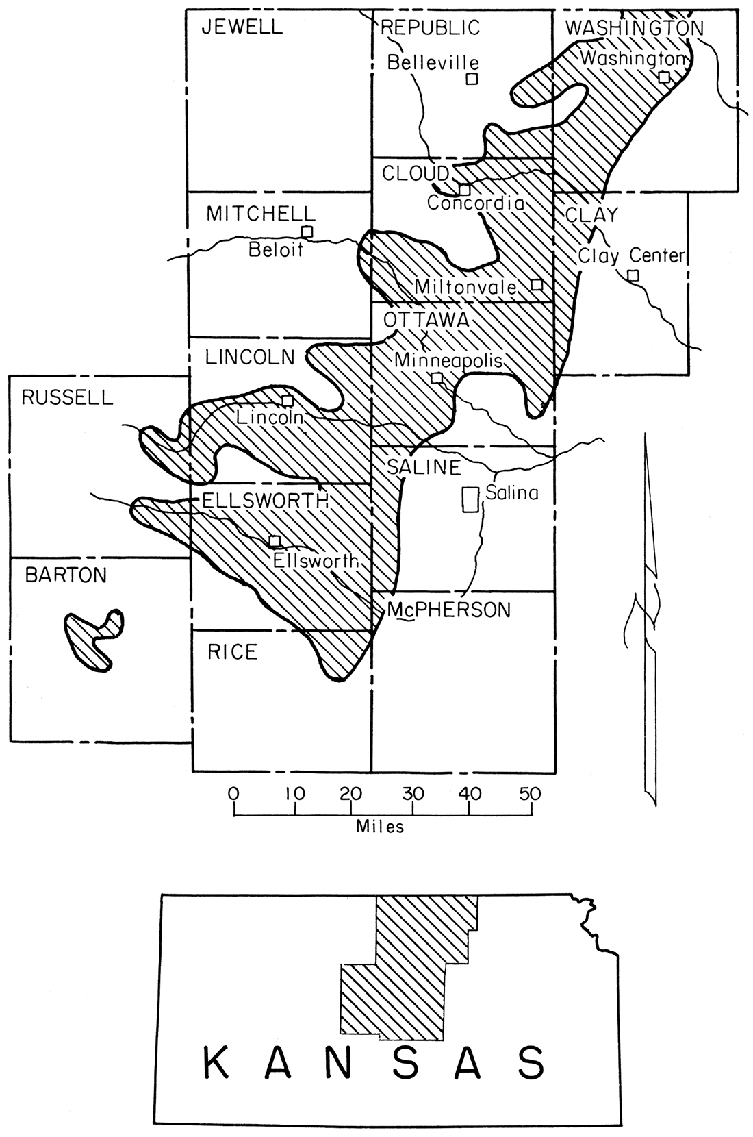
Figure 3 shows the differential thermal analysis curves of samples C-30-5, El-60-6, and El-20-6, in order of increasing quartz content. The presence of quartz was determined by running reheats on samples C-30-5 and El-60-6 after the initial pattern was obtained. Both C-30-5 and El-60-6' showed excellent wellcrystallized kaolinite mineral pattern. Kaolinite that is poorly crystallized exhibits a broad flat exothermic peak at 940 to 960°C, contrasted to the narrow sharp peaks shown here. Sample El-20-6 shows a strong alpha to beta quartz inversion (575°C). Weak kaolinite reactions are visible.
Figure 3—Typical differential thermal analysis curves for refractory clays and silts.
The curves show that the predominant clay mineral is kaolinite and the non-clay material is quartz. Small percentages of illite and other layer silicate minerals are not easily detected by the method. Work by Plummer and others (1954) has shown that small percentages of other layer silicates exist, but they are at a minimum in the more refractory clays.
Chemical analyses were made on each of the clay samples and are summarized in Table 3. The analyses consisted of quantitative determinations of loss on ignition and oxides of the following major elements: silicon, aluminum, calcium, magnesium, iron, titanium, potassium, and sodium. Sulfate sulfur and phosphorous pentoxide were determined, but only traces were noted. All chemical analyses were performed by the Geochemistry Laboratory of the Geological Survey of Kansas, using the method outlined by Plummer and others (1954).
Table 3—Chemical analysis of Kansas refractory clays and silts.
| Sample no. | SiO2 | Al2O3 | Fe2O3 | TiO2 | CaO | MgO | P2O5 | SO3 | K2O | Na2O | L.O.I. | Total | SiO2* (corrected for L.O.I.) |
|---|---|---|---|---|---|---|---|---|---|---|---|---|---|
| BT-3 | 77.33 | 12.67 | 1.61 | 1.86 | 0.12 | 0.38 | trace | trace | 1.39 | 0.14 | 4.29 | 99.79 | 80.70 |
| C-27-8 | 61.02 | 25.33 | 1.72 | 0.87 | 0.17 | 0.66 | 0.03 | trace | 1.75 | 0.16 | 8.90 | 99.80 | 66.98 |
| C-30-5 | 61.29 | 24.06 | 3.68 | 1.20 | 0.24 | 0.30 | trace | nil | 0.05 | 0.12 | 8.95 | 99.89 | 67.31 |
| C-35-6 | 62.70 | 24.53 | 2.58 | 0.97 | 0.48 | 0.39 | trace | trace | 0.55 | 0.16 | 8.16 | 100.52 | 68.27 |
| El-12-2 | 66.47 | 21.56 | 1.80 | 1.13 | 0.12 | 0.27 | 0.03 | 0.68 | 0.13 | 7.91 | 100.10 | 72.18 | |
| El-12-4 | 61.89 | 23.87 | 1.61 | 1.63 | 0.10 | 0.60 | 0.04 | nil | 0.55 | 0.13 | 9.61 | 100.03 | 68.47 |
| El-14-9 | 60.20 | 22.55 | 4.38 | 2.69 | 0.23 | 0.11 | 0.01 | 0.08 | 1.00 | 0.15 | 8.17 | 99.56 | 65.50 |
| El-20-W5 | 91.36 | 3.71 | 0.54 | 1.06 | 0.25 | 0.35 | n.d. | n.d. | n.d. | n.d. | 1.40 | 98.67 | 92.68 |
| El-20-6 | 94.49 | 2.53 | 0.03 | 1.36 | 0.10 | 0.11 | trace | 0.01 | 0.28 | 0.12 | 0.80 | 100.10 | 95.25 |
| El-29-4 | 70.81 | 18.84 | 1.20 | 1.38 | 0.53 | 0.29 | trace | 0.02 | 0.27 | 0.10 | 6.95 | 100.20 | 76.10 |
| El-29-10 | 62.08 | 24.38 | 1.55 | 1.51 | 0.56 | 0.28 | trace | 0.46 | 0.40 | 0.11 | 8.90 | 100.23 | 68.94 |
| El-45-3 | 59.90 | 25.17 | 2.42 | 1.43 | 0.20 | 0.11 | 0.02 | 0.03 | 1.98 | 0.13 | 7.46 | 99.35 | 64.73 |
| El-45-7 | 68.50 | 19.76 | 1.90 | 1.88 | 0.10 | 0.14 | trace | trace | 0.31 | 0.13 | 8.00 | 100.72 | 74.40 |
| El-57-A | 69.95 | 17.91 | 1.40 | 1.77 | 0.20 | 0.18 | trace | trace | 1.15 | 0.20 | 7.34 | 100.10 | 75.49 |
| El-60-B | 71.86 | 17.64 | 1.10 | 1.17 | 0.13 | 0.11 | trace | trace | 0.19 | 0.11 | 7.39 | 99.70 | 77.59 |
| El-60-6 | 73.26 | 17.86 | 0.65 | 1.25 | 0.14 | 0.15 | trace | trace | 0.06 | 0.05 | 6.48 | 99.90 | 78.34 |
| El-60-7 | 71.05 | 17.52 | 1.37 | 1.13 | 0.12 | 0.08 | 0.02 | 0.05 | 0.27 | 0.14 | 7.93 | 99.68 | 77.17 |
| El-60-13 | 74.33 | 16.64 | 0.68 | 1.39 | trace | 0.07 | 0.01 | 0.08 | 0.05 | 0.10 | 6.78 | 100.13 | 79.68 |
| El-72-3 | 69.39 | 19.02 | 1.23 | 1.24 | 0.08 | 0.63 | 0.01 | 0.12 | 1.87 | 0.13 | 7.76 | 101.48 | 75.23 |
| El-72-14 | 61.01 | 23.38 | 3.20 | 1.80 | 0.13 | 0.06 | 0.01 | 0.32 | 1.01 | 0.12 | 8.28 | 99.31 | 66.52 |
| El-73-C | 79.70 | 9.74 | 1.13 | 1.70 | 0.02 | 0.03 | 0.13 | 0.28 | 0.07 | n.d. | 6.90 | 99.70 | 85.61 |
| El-85-C** | 73.46 | 16.31 | 1.03 | 1.47 | 0.14 | 0.26 | 0.01 | 0.10 | 0.56 | 0.11 | 6.74 | 100.19 | 78.77 |
| El-85-11 | 93.92 | 2.96 | 0.39 | 0.82 | 0.11 | 0.05 | 0.19 | 0.01 | 1.01 | 99.46 | 94.88 | ||
| El-87-10 | 80.56 | 11.85 | 0.91 | 1.12 | 0.15 | 0.32 | 0.03 | 0.03 | 1.14 | 0.16 | 3.38 | 100.10 | 83.38 |
| El-105-4 | 69.98 | 17.58 | 1.27 | 1.23 | 0.63 | 0.25 | trace | n.d. | 0.26 | 0.15 | 8.96 | 100.31 | 76.87 |
| L-39-2 | 66.49 | 20.97 | 1.06 | 1.44 | 0.77 | 0.12 | 0.03 | 0.10 | 0.28 | 0.14 | 8.60 | 100.02 | 72.75 |
| O-5-6 | 61.87 | 23.93 | 1.42 | 1.37 | 0.41 | 0.45 | 0.02 | 0.05 | 0.66 | 0.21 | 8.93 | 99.32 | 67.94 |
| * Calculated percent SiO2 present for fired brick. ** Analysis calculated from component analyses. |
|||||||||||||
The major importance of a chemical analysis lies in showing the relative amounts of refractory oxides (SiO2, Al2O3) and flux oxides (Fe2O3, TiO2, CaO, MgO, Na2O, K2O) present. The latter group reduces the refractoriness of the clay.
The range of chemical composition for commercial fired refractories is shown in Table 4. These analyses were reported for fired (ignited) samples. To make these values comparable with those in Table 3, a correction must be made for loss on ignition. A corrected loss-on-ignition column for silica (SiO2) has been included in Table 3 to facilitate comparisons.
Table 4—Chemical composition ranges of fired refractories.*
| Percentage | ||||||||
|---|---|---|---|---|---|---|---|---|
| SiO2 | Al2O3 | Fe2O3 | TiO2 | CaO | MgO | Na2O K2O |
||
| Normal and extra fire super duty |
51-54 | 40-43 | 1.4-2.3 | 2.1-2.5 | 0.2-0.5 | 0.2-0.5 | 0.8-1.4 | |
| Kaolin type super duty |
50-53 | 44-46 | 0.5-1.2 | 1.0-2.0 | 0.10 | 0.22 | 0.04 | |
| High duty | 51-59 | 35-40 | 1.6-2.5 | 2.0-3.0 | 0.3-0.5 | 0.5-0.6 | 1.5-2.6 | |
| Intermediate duty |
56-60 | 25-36 | 1.8-3.4 | 1.3-1.9 | 0.2-0.4 | 0.5-0.6 | 1.0-2.7 | |
| Low duty | 53-69 | 25-34 | 2.3-3.4 | 1.0-2.0 | 0.3-0.6 | 0.4-0.6 | 1.8-2.9 | |
| Siliceous type high duty |
65-78 | 19-21 | 0.9-1.4 | 1.0-1.3 | 0.1-0.2 | 0.2-0.4 | 0.3-1.1 | |
| Silica brick | ||||||||
| Super duty | 96.4-97.4 | 0.2-0.4 | 0.3-0.6 | 0.03-0.06 | 2.2-3.0 | 0.05-0.06 | ||
| Conventional | 94.9-96.5 | 0.6-1.2 | 0.4-0.7 | 0.04-0.10 | 2.0-3.5 | 0.05-0.25 | ||
| * Kirk and Othmer, 1953, p. 602. | ||||||||
Silica content of all clays analyzed is high, indicating that free quartz is present. The percent silica present, corrected for loss on ignition, categorizes the clays in the semi-silica refractory area of the alumina-silica equilibrium diagram (Fig. 1). Silt sample El-20-6 is near the composition for conventional silica bricks.
The alumina content of all the samples is low, as would be expected because the silica content is high. Clay samples C-35-6, C-30-5, El-14-9, and El-72-14 contain iron oxide in excess of 2 percent; this is undesirable because of the fluxing effect of iron oxide.
Titania (TiO2) is at a satisfactory level, and almost uniform in all samples except El-14-9. Wilder and Dodd (1953) have reported that titania present in amounts less than 2 percent has negligible effects on glass formation and refractoriness of refractory clays.
Calcium oxide and magnesium oxide are not present in large enough quantities to seriously affect refractoriness. Alkalies, sodium oxide and potassium oxide, range from 0.1 percent to 2 percent total. In few samples does sodium oxide exceed 0.2 percent. Total alkali content exceeding 1 percent may reduce the refractory load carrying characteristics.
Full-size refractory bricks, 9 × 4 1/2 × 2 1/2 inches, were formed from the refractory clay and silt samples by the dry-pressing method, and by the general procedure outlined in the flow sheet (Fig. 4).
Figure 4—Flow chart for preparation of laboratory brick.
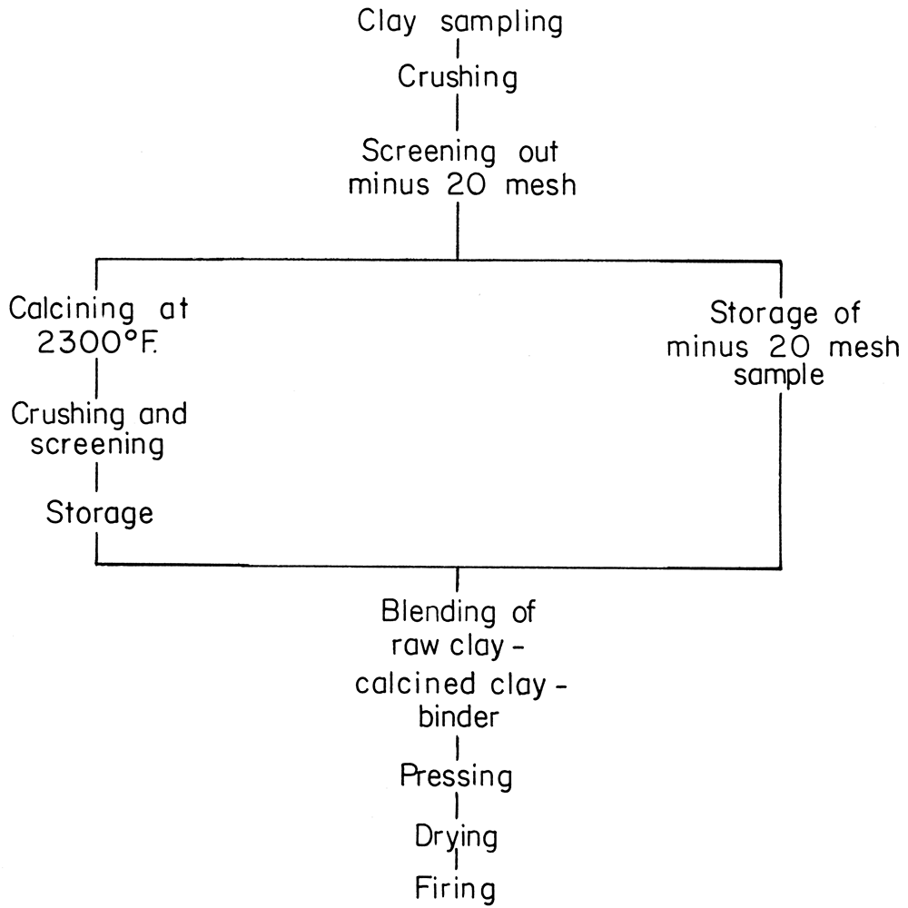
Large lumps of the raw material were broken by hand to 1 inch or smaller. Further reduction was done in a dry pan. The crushed sample, approximately 20 mesh, was divided into two portions, one for calcining, the other for raw clay binder.
Calcining is a high-temperature heat treatment preparatory to the use of the clay. Calcining burns out combustible materials, drives off volatile chemical constituents, causes shrinkage, and develops certain desired physical conditions. The use of calcined material in a brick reduces the firing shrinkage and warpage, and permits a faster rate of firing during the early oxidation period. Calcined clay is often called "grog", a term also given to ground firebrick.
For bricks made with clay from more than one bed at a sample location, the clays were blended, before calcining, in approximately the same weight proportions one would obtain by taking a vertical cut through the section sampled (Table 5).
All samples were calcined at 2300° F. For convenience in producing the proper particle size distribution of calcined clay, the samples were extruded into bars, dried, and calcined. Calcining test runs were made in a laboratory-size rotary kiln. Results were not satisfactory, because much of the fine material was blown out of the kiln.
Table 5—Bed blended samples.
| Sample code | Bed code | Weight percent |
|---|---|---|
| El-57-A | El-57-2 | 31.8 |
| El-57-4 | 42.2 | |
| El-57-6 | 26.0 | |
| El-60-B | El-60-6 | 37.0 |
| El_60-7 | 63.0 | |
| El-73-C | El-73-2 | 45.0 |
| El-73-3 | 55.0 | |
| El-85-C | El-85-3 | 43.7 |
| El-85-4 | 56.3 |
After calcining, the sintered-hard material was crushed to a usable size (minus 6 mesh) by jaw crushers and roll crushers.
Norton (1949) has pointed out that sizing of the nonplastic material (grog) produces denser bricks because tighter packing of the particles is possible if certain particle size distributions are used. His recommended size ranges for grog were: 6-10 mesh, 20-48 mesh, and through 48 mesh. Material in the 10-20 mesh size was undesirable for tight-packing mixtures and was crushed to a smaller size and used in the bricks.
The calcined portion of each sample was screened into the above three sizes and stored for further use.
The following distribution of particle size was reported by Norton (1949) as giving satisfactory packing:
| Through | On | Percent |
|---|---|---|
| 6-mesh | 10-mesh | 40 |
| 20-mesh | 48-mesh | 20 |
| 48-mesh | 40 |
To the above blend of sized calcined material were added a certain amount of raw sample, moisture, and if needed, an organic binder, as listed in Table 6. All batches were mixed in a muller-type mixer to thoroughly disperse the material and the moisture.
Table 6—Grog-raw clay mixtures for test bricks.
| Sample no. |
Parts by weight | ||||
|---|---|---|---|---|---|
| Raw clay |
Calcined clay |
Water | Glutrin* | Goulac | |
| C-27-8 | 20 | 80 | 6 | ||
| C-30-5 | 20 | 80 | 8 | ||
| C-35-6 | 20 | 80 | 8 | ||
| El-12-2 | 20 | 80 | 8 | ||
| El-12-4 | 20 | 80 | 8 | ||
| El-14-9 | 20 | 80 | 7.5 | ||
| El-20-W5 | 50 | 50 | 5 | 2 | |
| El-20-6 | 50 | 50 | 6 | 3 | |
| El-29-4 | 20 | 80 | 8 | ||
| El-29-10 | 20 | 80 | 8 | ||
| El-45-3 | 20 | 80 | 8 | ||
| El-45-7 | 20 | 80 | 8 | ||
| El-57-A | 20 | 80 | 8 | 2 | |
| El-60-6 | 50 | 50 | 5 | 3 | |
| El-60-7 | 33 | 67 | 6 | 3 | |
| El-60-13 | 30 | 70 | 8 | ||
| El-60-B | 50 | 50 | 8 | 2 | |
| El-72-3 | 20 | 80 | 8 | ||
| El-72-14 | 20 | 80 | 8 | ||
| El-73-C | 20 | 80 | 8 | ||
| El-85-C | 20 | 80 | 8 | 2 | |
| El-85-11 | 50 | 50 | 8 | 3 | 2 |
| El-87-10 | 50 | 50 | 8 | ||
| El-105-4 | 20 | 80 | 8 | ||
| BT-3 | 25 | 75 | 8 | ||
| L-39-2 | 20 | 80 | 8 | ||
| O-5-6 | 20 | 80 | 8 | ||
| * Glutrin is liquid goulac. Goulac is a binder obtained from the waste liquor of the sulfite-pulp paper process. | |||||
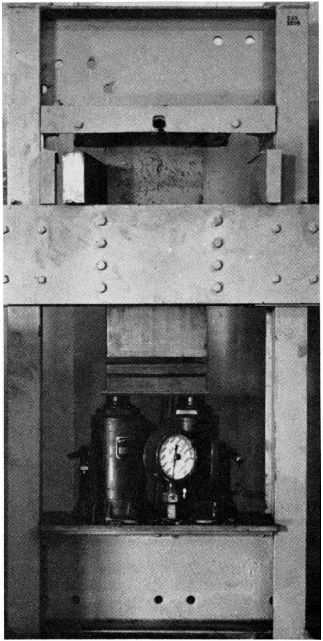
Immediately after mixing, the prepared batches were pressed at 2000 psi into bricks in a specially constructed laboratory press (Plate 1).
Plate 1—Press for dry-pressing refractory bricks.
Pressed bricks were air-dried before firing.
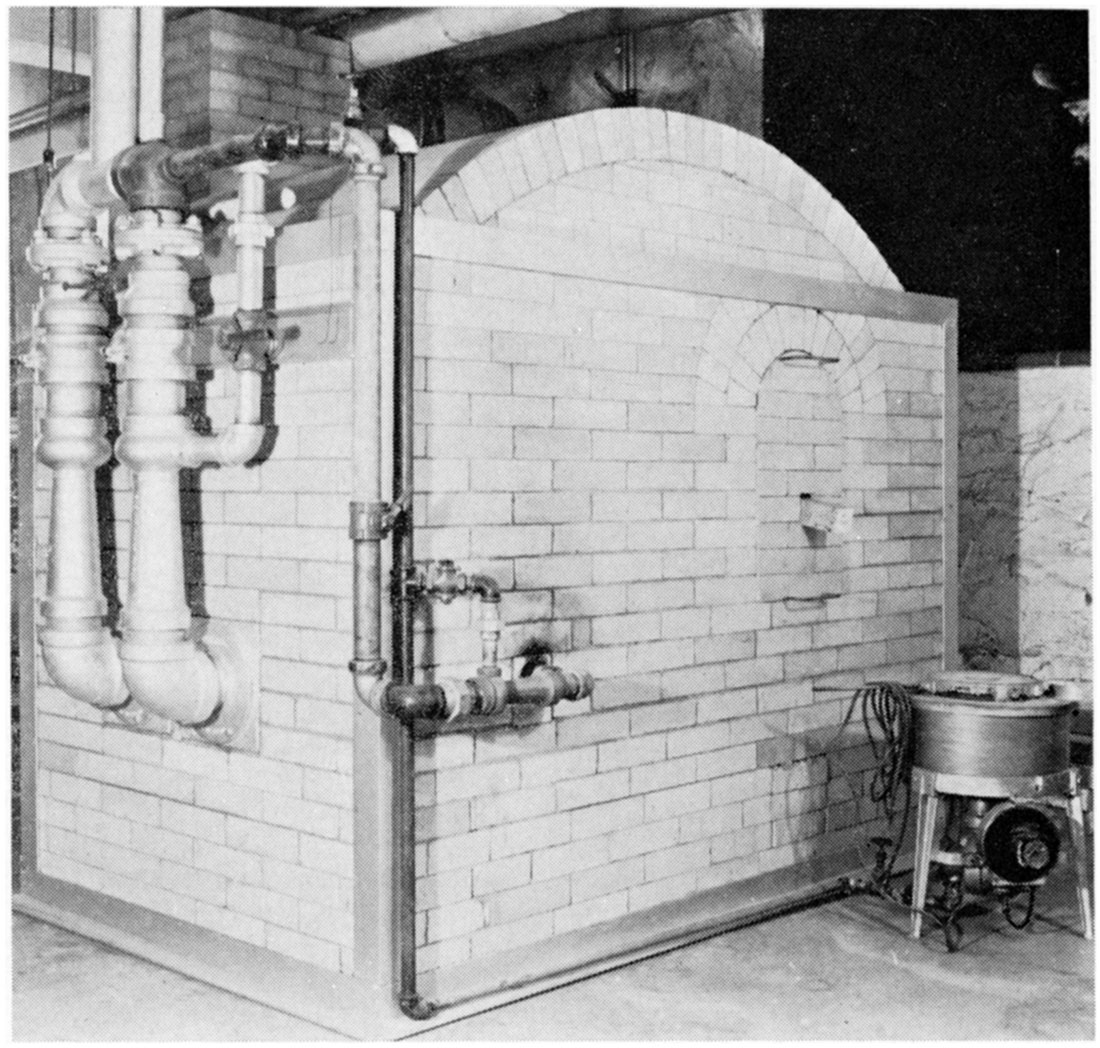
All samples, except BT-3 (PCE of 23), were fired in a downdraft gas-fired kiln (Plate 2). Several firings of the same sample were made and the firings varied between cone 16 (2642° F) and cone 19 (2759° F). A 24-hour firing schedule was used with a 2-hour soak at peak temperature. Cooling was at the normal rate of kiln cooling.
Plate 2—Gas-fired down-draft kiln. PCE furnace at right.
Many of the clays used to make the dry-pressed refractory bricks were also investigated by the Ceramic Section of the State Geological Survey of Kansas in 1942 for their usability in the manufacture of light-colored face brick by plastic extrusion methods. This information is introduced here for two reasons: (1) to record the information permanently and (2) to show the effects of calcining part of the clay used. The data in Table 7 indicate that many of the clays will make satisfactory face brick.
The total shrinkage data in Table 9 emphasize the desirability of using as much calcined clay as possible to produce dimensionally uniform bricks and to minimize warpage. The total drying and firing shrinkages of the raw clay (Table 7) ranged from +0.54 to -18.4 percent for firings not exceeding cone 14. When most of the clay was calcined and the bricks were fired to cone 16-19, the firing shrinkage (Table 9) ranged only from +1.90 to -2.60 percent. Stated in another way, a freshly formed unfired brick 12 inches long made from 100 percent plastic clay would be 10 3/4 inches long after firing. If 80 percent of the clay were calcined, however, the fired length of a 12-inch brick would be about 11 3/4 inches. It is much easier to hold close quality controls on 1/4 inch shrinkage than it is on 1 1/4 inch shrinkage.
Table 7—Fired properties of test bricks made from raw clay samples.
| Sample no. | Fired to cone |
Fired color |
Total drying and firing shrinkage (%) |
Percent absorption boiling water 5 hrs. |
|---|---|---|---|---|
| C-27-8 | 02 | Cream | 12.84 | 4.58 |
| 5 | Cream | 14.37 | 2.42 | |
| C-30-5 | 06 | Buff | 5.67 | 15.98 |
| 1 | Pink | 7.89 | 11.68 | |
| 3 | Pink | 9.30 | 9.20 | |
| C-35-6 | 03 | Cream | 8.43 | 9.54 |
| 2-3 | Pale salmon | 12.65 | 6.15 | |
| 5 | Cream | 12.50 | 3.44 | |
| 7 | Ivory | 13.47 | 4.14 | |
| 11 | Light brown | 14.36 | 0.66 | |
| El-12-2 | 03 | Cream | 9.34 | 13.90 |
| 01 | Cream | 10.37 | 10.78 | |
| 5 | Cream | 11.47 | 8.66 | |
| 8 | Cream | 11.55 | 8.72 | |
| 11 | Gray | 11.83 | 5.42 | |
| El-12-4 | 05 | Cream | 9.64 | 13.49 |
| 02 | Cream | 12.05 | 10.21 | |
| 5 | Cream | 13.57 | 4.84 | |
| 8 | Cream | 13.23 | 4.01 | |
| 12 | Grayish cream | 14.52 | 2.22 | |
| El-14-9 | 06 | Tan | 7.96 | 9.63 |
| 4 | Buff | 11.41 | 3.56 | |
| 6 | Buff | 13.30 | 3.74 | |
| El-20-W5 | 13 | Cream | +.54 | 25.16 |
| El-20-6 | 13-14 | Cream | +0.30 | 22.56 |
| El-29-4 | 05 | White | 5.98 | 13.65 |
| 01 | White | 5.98 | 11.65 | |
| 5 | Ivory | 7.23 | 10.51 | |
| 8 | Cream | 7.75 | 10.25 | |
| 11 | Cream | 8.90 | 8.90 | |
| El-29-10 | 05 | Cream | 7.68 | 15.25 |
| 01 | Cream | 9.60 | 13.03 | |
| 5 | Cream | 10.97 | 10.23 | |
| 9 | Cream | 11.11 | 9.S9 | |
| 12 | Cream | 11.11 | 8.67 | |
| El-45-3 | 06 | Cream | 13.10 | 10.67 |
| 5 | Buff | 18.40 | 1.14 | |
| El-45-7 | 06 | Cream | 1.32 | 20.19 |
| 01 | Cream | 9.21 | 16.37 | |
| 5 | Cream | 9.96 | 14.51 | |
| 8 | Ivory | 9.83 | 13.99 | |
| 11 | Cream | 10.04 | 12.89 | |
| El-57-A | 05 | Cream | 6.23 | 13.98 |
| 1 | Cream | 7.11 | 10.45 | |
| 4 | Cream | 8.13 | 7.12 | |
| 9 | Cream | 8.57 | 6.69 | |
| 12 | Cream | 8.69 | 5.42 | |
| El-60-B | 05 | Buff | 3.93 | 17.65 |
| 1 | Pink | 4.61 | 15.96 | |
| 4 | Ivory | 5.84 | 14.40 | |
| 9 | Cream | 5.84 | 13.77 | |
| 12 | Cream | 5.85 | 13.02 | |
| 14 | Cream buff | 6.74 | 12.66 | |
| El-60-6 | 03 | White | 4.50 | 14.77 |
| 01 | White | 6.68 | 14.81 | |
| 5 | Ivory | 6.93 | 14.56 | |
| 9 | White | 7.68 | 14.21 | |
| 13 | Pinkish white | 7.56 | 13.64 | |
| El-60-7 | 02 | Light buff | 6.88 | 13.98 |
| 5 | Cream | 8.72 | 14.56 | |
| 8 | Cream | 8.56 | 13.87 | |
| 13 | Cream | 8.87 | 13.93 | |
| El-60-13 | 05 | White | 3.64 | 15.10 |
| 01 | White | 5.89 | 15.29 | |
| 5 | White | 6.77 | 14.85 | |
| 9 | White | 7.36 | 14.17 | |
| 12 | Ivory | 7.03 | 13.34 | |
| El-72-3 | 05 | Cream | 7.23 | 12.77 |
| 01 | Cream | 7.99 | 10.24 | |
| 4 | Cream | 9.11 | 8.08 | |
| 8 | Cream | 10.26 | 3.66 | |
| 11 | Light gray | 10.99 | 1.71 | |
| El-72-14 | 05 | Pink buff | 9.79 | 13.49 |
| 3 | Light tan | 12.99 | 7.26 | |
| 5 | Cream | 12.17 | 4.38 | |
| El-85-C | 05 | Ivory | 3.94 | 14.80 |
| 1 | Ivory | 4.94 | 12.40 | |
| 4 | Ivory | 5.12 | 11.62 | |
| 9 | Ivory | 5.58 | 10.89 | |
| 12 | Cream | 5.78 | 9.44 | |
| El-87-10 | 01 | Cream | 6.01 | 9.25 |
| 4 | Cream | 6.60 | 9.62 | |
| 8 | Cream | 7.45 | 7.29 | |
| 11 | Cream | 7.43 | 6.89 | |
| El-105-4 | 06 | Pink | 4.44 | 16.56 |
| 02 | Cream | 5.34 | 16.48 | |
| L-39-2 | 02 | Ivory | 7.92 | 13.69 |
| 4 | Cream | 9.21 | 11.76 | |
| 9 | Ivory | 9.92 | 10.38 | |
| 12 | Cream | 10.07 | 8.98 | |
| O-5-6 | 05 | Light buff | 9.81 | 14.06 |
| 02 | Dark cream | 11.41 | 11.10 | |
| 4 | Light buff | 13.66 | 5.97 | |
| 8 | Dark cream | 13.78 | 3.20 | |
| 10 | Yellow tan | 14.49 | 1.02 |
The only satisfactory method of evaluating the serviceability of a refractory brick is to install it in a furnace or kiln and observe its actual performance under operating conditions. Few companies are interested in undertaking such a test, however, without some preliminary screening of the various types of refractory bricks. Certain physical tests on full-size bricks have been developed to predict the probability of satisfactory service. Three common tests are (1) refractory hot load test, (2) permanent linear change or reheat or volume stability test, and (3) fired transverse strength. Typical values for the physical behavior of commercial refractories are shown in Table 8. Numerous other special tests, such as resistance to spalling, attack by slags, and disintegration by carbon monoxide, require special equipment not available in the Geological Survey laboratory.
Table 8—Typical values for physical behavior of commercial refractories.*
| Type | Modulus of rupture (p.s.i.) |
Subsidence after 1 1/2 hrs. at 1350° C. (%) |
Reheat change at ° C. (%) |
|---|---|---|---|
| High duty | 600-1000 | 2-6 | +3.0 to -1.0 (1400) |
| Intermediate duty | 800-1200 | 3-10 | +3.0 to -1.0 (1400) |
| Low duty | 800-1200 | 8-10 | +2.0 to -1.0 (1200) |
| High duty (siliceous type) |
600-1000 | 0.3-1.4 | +0.2 to -0.2 (1400) |
| * Kirk and Othmer, 1953, p. 614. | |||
In many applications refractories are required to support loads while at high temperatures, therefore excessive yield or deformation cannot be tolerated. The mechanism of hot load failure is generally governed by: (1) the flow characteristics of the glass bonding material, (2) the flow characteristics of the crystalline material, and (3) the interaction between the two materials.
The hot compressive or load test (A.S.T.M. C-16-49) was carried out by applying a compressive static load of 25 psi throughout a specified heating period to a 9-inch straight brick standing on end. Heating was done in a Harper hot load testing furnace (Plate 3) that was designed according to A.S.T.M. C-16-49 test specifications. A Bristol program controller regulated the heating schedule. Heating schedule No. 2, 1350°C (2460° F) with a soaking period of 1 1/2 hours at maximum temperature, was used. A tabulation of the percent linear change of the various bricks is reported in Table 9.
Plate 3—Furnace for hot load testing.
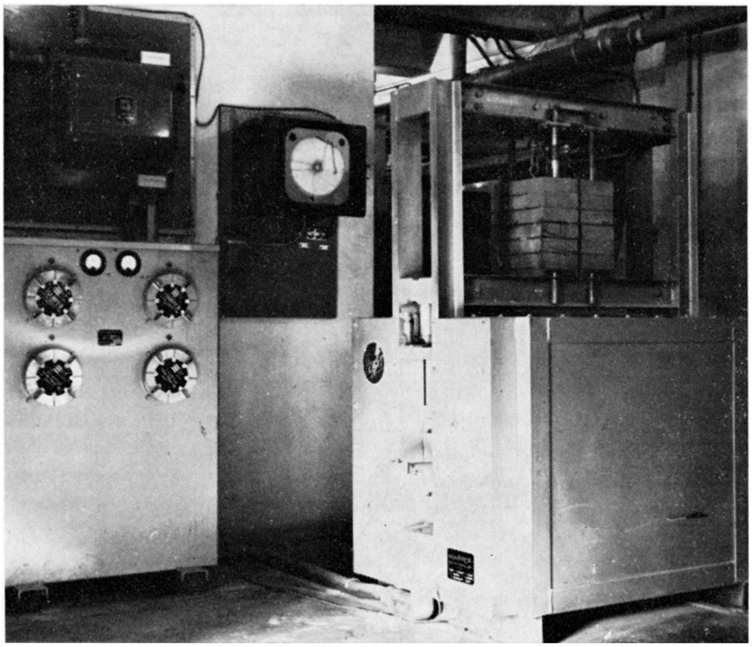
Table 9—Physical properties of refractory bricks made from Kansas clay.
| Code | % Total drying and firing shrinkage |
Fired to cone |
Hot load test, % length change* |
Reheat test, % linear change |
Modulus of rupture, psi |
Water absorption, % |
Bulk density, lb./per cu. ft. |
|---|---|---|---|---|---|---|---|
| BT-3 | -2.22 | 13 | -1.50 | +0.33 | 650 | 11.0 | 121 |
| C-27-8 | +0.89 | 19 | -3.30 | -0.34 | 500 | 6.6 | 121 |
| C-30-5 | -0.52 | 18 | -0.20 | -0.06 | 800 | 15.0 | 114 |
| C-35-6 | -0.64 | 18 | +0.01 | +0.09 | 1250 | 14.4 | 110 |
| El-12-2 | -0.55 | 18 | -0.35 | +0.11 | 800 | 14.2 | 116 |
| El-12-4 | +0.52 | 19 | -0.30 | +0.16 | 850 | 14.7 | 109 |
| El-14-9 | -0.85 | 18 | -2.60 | +0.15 | 900 | 8.2 | 127 |
| El-20-W5 | +1.65 | 18 | +0.05 | … | … | 28.9 | 85 |
| El-20-6 | +1.85 | 18 | +0.14 | … | … | 27.8 | 90 |
| El-29-4 | -2.60 | 19 | +0.05 | +0.26 | 700 | 13.7 | 112 |
| El-29-10 | -1.26 | 18 | -0.07 | -0.16 | 300 | 13.1 | 117 |
| El-45-3 | +0.81 | 19 | -1.21 | … | … | 7.4 | 121 |
| El-45-7 | +0.95 | 19 | -0.07 | +0.12 | 250 | 22.7 | 100 |
| El-57-A | -0.11 | 16 | +0.25 | +0.05 | 800 | 14.0 | 108 |
| El-60-6 | +1.90 | 18 | -0.07 | +0.25 | 300 | 16.2 | 110 |
| El-60-7 | +1.36 | 18 | -0.12 | … | … | 20.9 | 101 |
| El-60-13 | +0.70 | 19 | -0.20 | +0.20 | 150 | 22.8 | 100 |
| El-60-B | +1.20 | 16 | -0.16 | +0.27 | 300 | 18.3 | 103 |
| El-72-3 | +1.10 | 18 | -1.05 | -0.19 | 1500 | 9.4 | 111 |
| El-72-14 | -0.97 | 19 | -0.85 | -0.08 | 1400 | 6.6 | 122 |
| El-73-C | +0.60 | 19 | -0.43 | … | … | 20.5 | 100 |
| El-85-C | +0.44 | 18 | 0.00 | +0.02 | … | 17.2 | 108 |
| El-85-11 | +1.89 | 16 | -0.11 | +0.55 | … | 26.2 | 94 |
| El-87-10 | +2.05 | 19 | +0.02 | +0.68 | 300 | 17.2 | 109 |
| El-105-4 | -1.80 | 19 | -0.22 | +0.12 | 1150 | 15.3 | 109 |
| L-39-2 | -2.15 | 19 | -0.04 | -0.03 | 750 | 14.0 | 118 |
| O-5-6 | -1.73 | 19 | -0.03 | +0.03 | 2100 | 8.3 | 119 |
| NOTE: … No test made; bricks were either cracked or of insufficient number for the test. + Indicates expansion. - Indicates shrinkage. * Percentages reported are averages for two bricks. |
|||||||
Many of the bricks showed an actual length increase during hot load testing. It is attributed to continued conversion of free quartz into cristobalite. On the basis of load test only, all samples except two (C-27-8, El-14-9) met the A.S.T.M. specification for semi-silica refractories, i. e., load deformation of less than 1.5 percent.
None of the bricks showed excessive hot load deformation for refractory usage. Hot load deformation characteristics seem to be unrelated to transverse breaking strength at room temperature. Bricks of both high and low breaking strength are pictured in Plates 4 and 5. No hot load deformation is seen in either group.
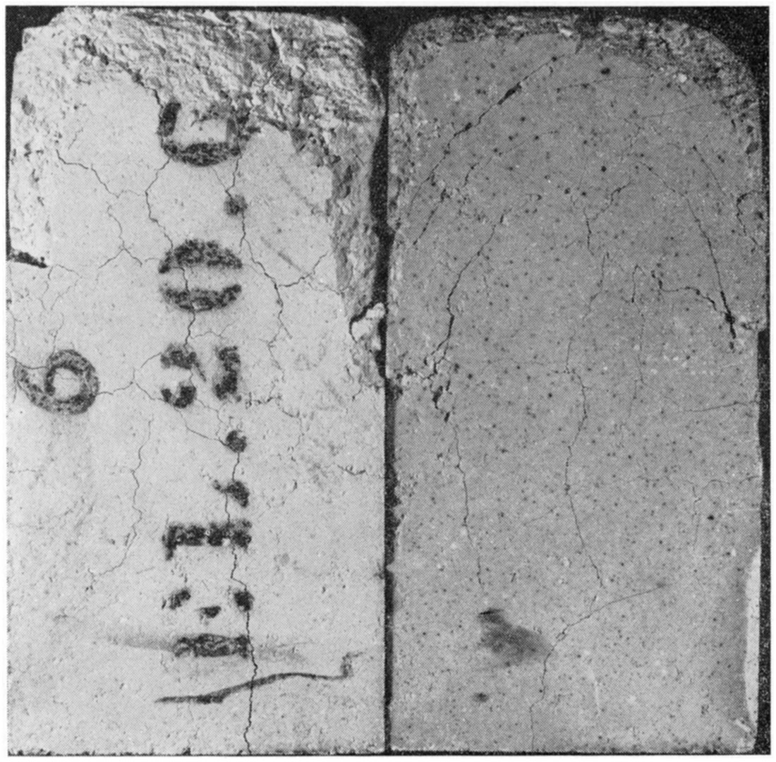
Bricks El-20-6 and El-20-W5, which contained large percentages of free quartz, had excellent load-carrying characteristics but showed spalling because of very poor thermal shock resistance (Plate 6). With slow heating through the silica inversion temperatures, spalling due to thermal shock would not be a problem.
Plate 4—Bricks having acceptable handling strength after hot load testing.
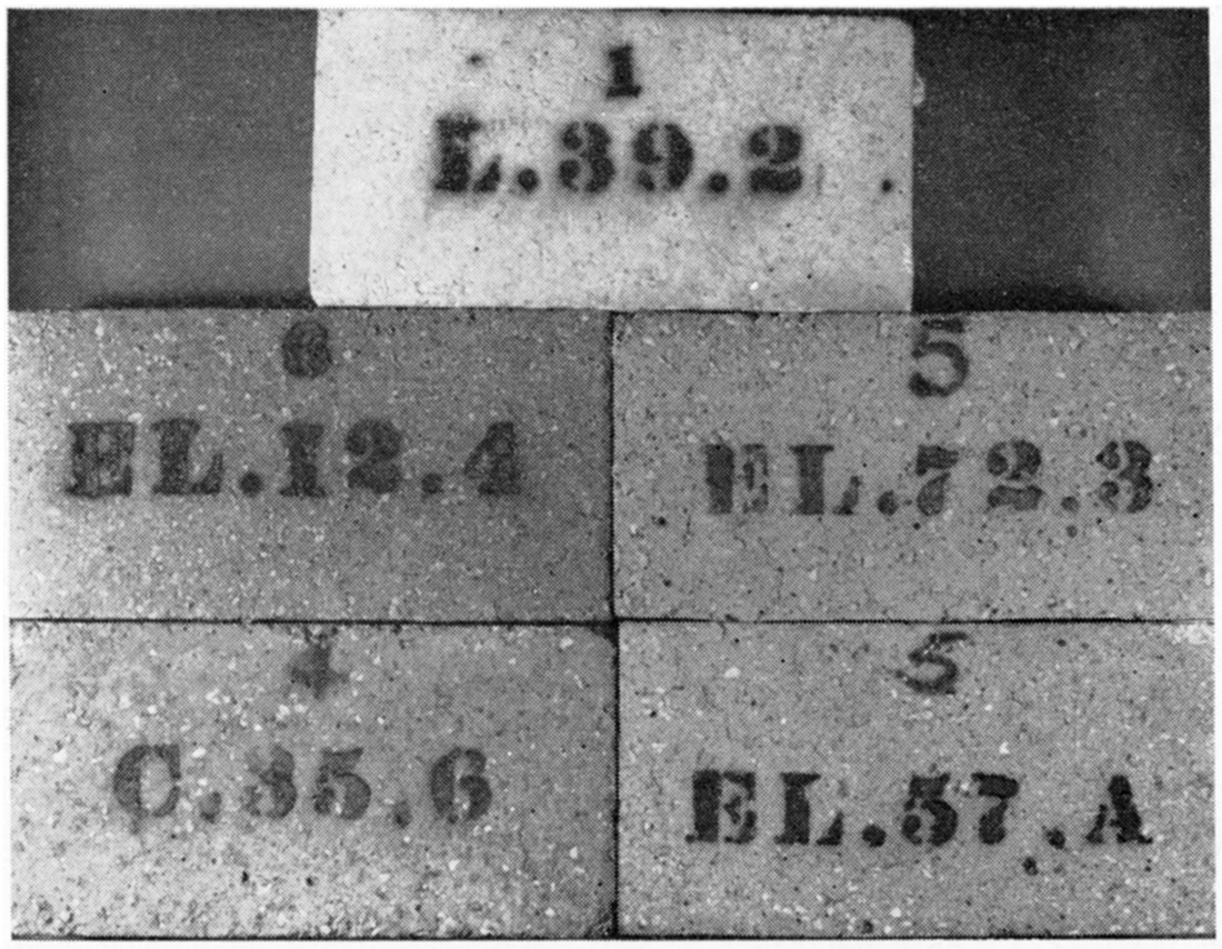
Plate 5—Bricks having non-acceptable handling strength after hot load testing. (Notice; They appear the same as bricks having acceptable handling strength.)
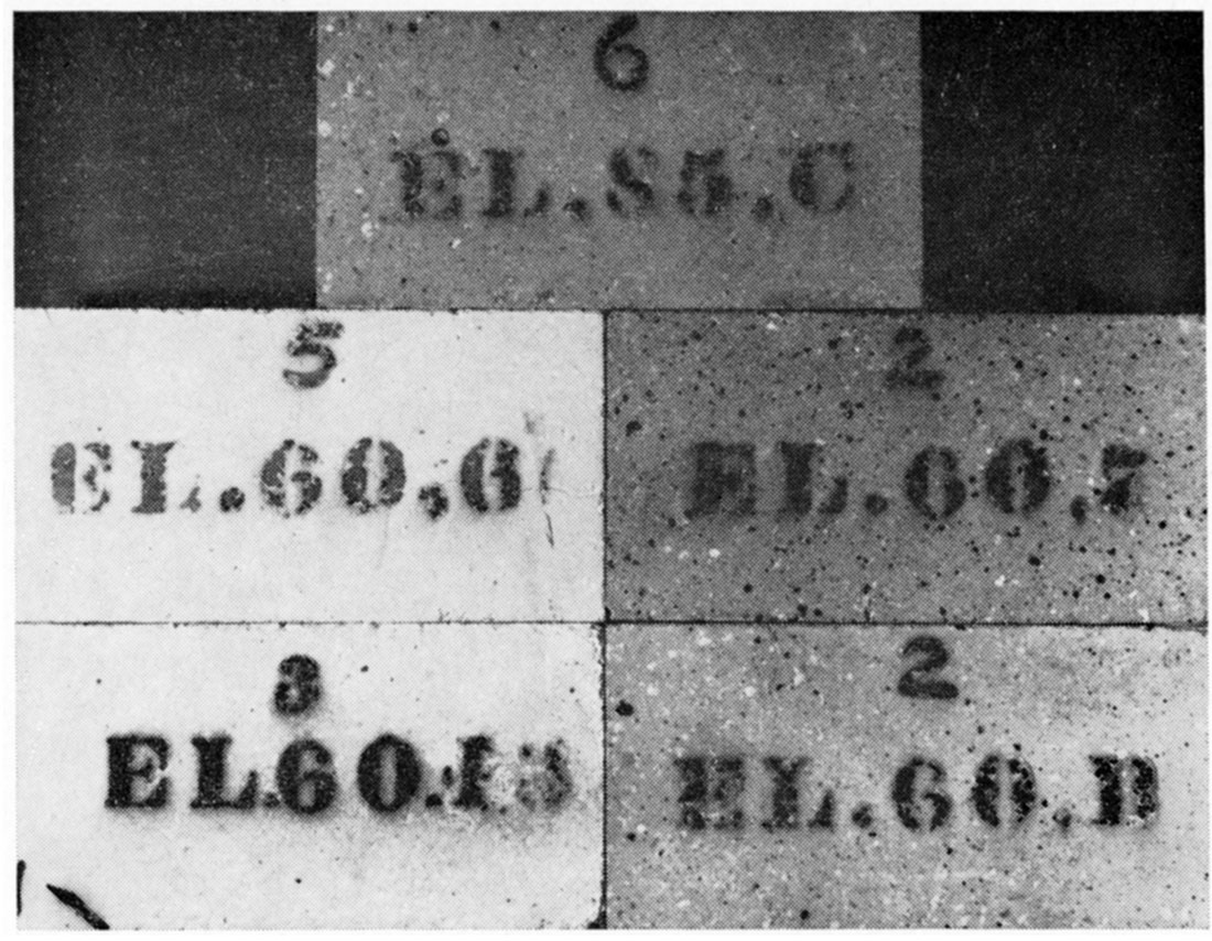
Plate 6—High-silica-content bricks showing thermal shock induced by load-test heating.
When a refractory brick is fired, a permanent change occurs in the material, causing the brick to have a different size from the original molding size. It is desirable that these changes be as complete as possible during firing, to prevent excessive expansion or shrinkage in later service. Unfortunately, more time may be required to complete the reactions than is allotted in the original firing period. Therefore, in service, if the operational temperature is high enough and is maintained for a sufficient length of time, there will be additional change in dimensions, generally slight but permanent. It may be either an expansion or a contraction. Excessive changes in dimensions could have a harmful effect on the stability of any structure formed from such refractories.
The determination of the permanent change in dimension was made according to the standard reheat test (A.S.T.M. C-113-46), and in a gas-fired down-draft type kiln (Plate 2) designed according to the A.S.T.M. specifications. Heating schedule B, 1400°C (2550° F) with a 5-hour hold at 1400°C, was used. Length of the bricks was measured before and after reheating by use of an Ames dial and precision measuring table.
Reheat test results are shown in Table 9. Most of the bricks had good volume stability. Bricks such as El-20-6 and El-20-W5, which cracked excessively during the original firing, were not reheat tested. Bricks from El-85-11 and El-87-10 samples, which contained much free quartz, showed excessive expansion (in excess of 0.5 percent) during reheating. Expansion indicate that part of the quartz had not been converted to either cristobalite or tridymite during the initial firing. X-ray diffractograms of the high-silica-content bricks verified this condition.
The strength of a brick at room temperature provides little indication of its strength at operational temperatures, but must be high enough to prevent scuffing and breaking during shipment.
Because only a few bricks were made, the modulus of rupture (transverse or flexure strength) test was made on the bricks used for the reheat test. Three bricks were broken for each sample tested. Although three bricks are not enough to provide a statistically valid breaking strength, they can provide an estimate of the strength.
Testing was carried out according to A.S.T.M. procedure C-133-55. Breaking was done on a Tinius Olsen Plastiversal testing machine; loading rate was 0.05 inch per minute. Small flaws such as firing and pressing cracks acted as starting areas for major breaking cracks when the brick was loaded. Highly siliceous bricks, such. as El-20-6, El-20-W5, and El-85-11, which contained large firing cracks, were not tested.
Modulus of rupture values (Table 9) range from 150 to 2200 psi. Minimum acceptable modulus of rupture value for semisilica brick according to A.S.T.M. designation C-27 -58 is 300 psi.
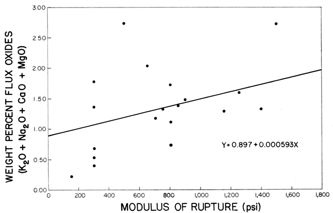
On the assumption that a linear relationship existed between the total amount of flux oxides (K2O, Na2O, CaO, MgO) and the modulus of rupture, the line in Figure 5 was constructed by the method of least squares. The ratio of the correlation coefficient r=0.676 to the standard error of correlation coefficient ar=0.1214 was 5.56, indicating that the total percentage of flux oxides in the raw clay had a significant effect on the modulus of rupture of the fired brick. A low total flux content produced a weak brick.
Figure 5—Effect of flux content on modulus of rupture.
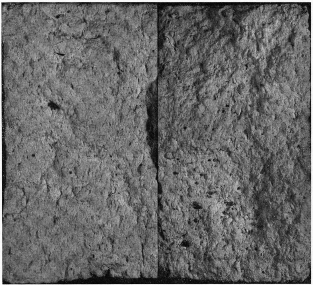
Broken bricks of coarse-, medium-, and fine-grained texture are shown in Plates 7 through 9. The internal texture appears uniform throughout each brick. When the fine-grained, weak bricks were broken, the grains "tore" apart instead of breaking with the customary "bang" of the stronger bricks.
The blending of refractory clay of higher fired strength with the clay having lower fired strength should produce a brick of sufficient strength for handling. No difference was noted in hot load strength between weak bricks and strong bricks.
Plate 7—Broken brick C-30-5, coarse texture, modulus of rupture 800 psi.
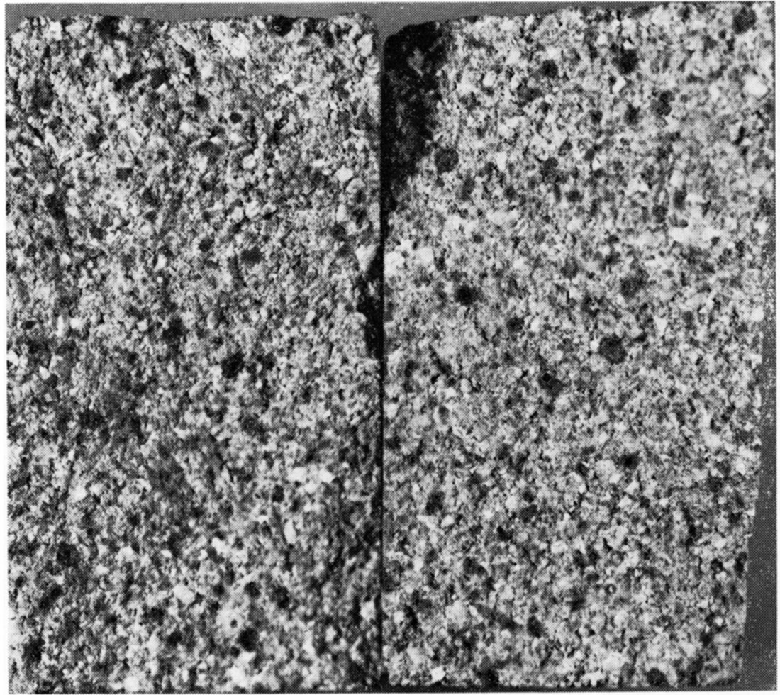
Plate 8—Broken brick L-39-2, medium texture, modulus of rupture 750 psi.
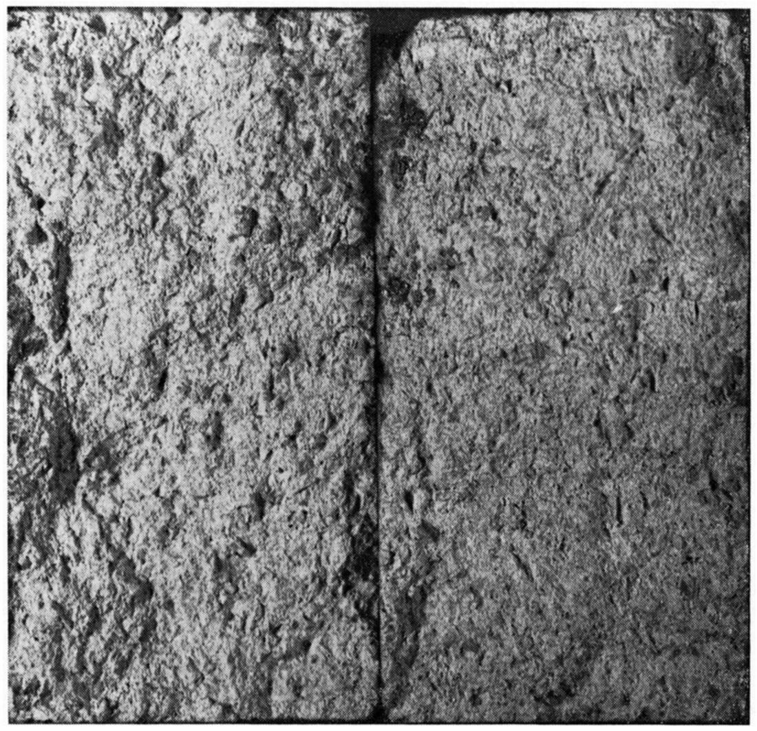
Plate 9—Broken brick El-60-13, fine texture, modulus of rupture 150 psi.
Water-absorption tests were made on the bricks used for hot load testing. The test was modified to the extent that whole bricks were tested instead of half bricks (A.S.T.M. designation C-20-46). Results are listed in Table 9.
Absorption values are not specified for the various grades of refractories, but refractory bricks that are to retain molten metals should have a low absorption to minimize metal penetration into the brick. On the other hand, porous bricks would have a lower thermal conductivity than dense bricks and would tend to hold heat in a furnace.
Density is the weight of material per unit volume. The bulk volume used in bulk density measurements includes the volume of the material itself plus the volume of both closed and open pores. Bulk density is the actual weight of a unit volume of the brick.
Bulk density of the various bricks was estimated by determining the volume of the brick by measuring with a precision vernier caliper, calculating the volume, and weighing the brick to the nearest gram. Values reported (Table 9) seem to be slightly lower than for industrial bricks, but bulk density will vary with degree of particle packing and with forming pressure.
X-ray diffraction patterns were made for powdered samples (minus 62 microns) taken from fired bricks made from samples C-27-8, El-60-13, and El-20-6, which range from the lowest level to highest level of silica. A General Electric XRD-3 proportional counting spectrogoniometer, nickel-filtered copper radiation, and a scanning rate of 2° 2θ per minute were used.
All patterns showed that about half the quartz had been converted to cristobalite and a trace of tridymite but the other half was not transformed. Increases in length upon refiring, observed early in the project, were attributed to the transformation of quartz to cristobalite, which is accompanied by a volume increase; presence of untransformed quartz after the first firing substantiates this interpretation. Free quartz in a brick is not desirable and can be reduced by extending the firing soak period and possibly by adding small amounts of lime to act as a mineralizer to accelerate transformation. Large quantities of untransformed quartz are undesirable because: (1) quartz has a rapid inversion rate (at 575°C) between the alpha and beta forms, and accompanying structural volume change may cause cracking of the brick during heating; and (2) quartz will slowly convert to either tridymite or cristobalite with an accompanying volume change that will cause the brick to grow while in high-temperature service.
The patterns from bricks made from C-27-8 and El-60-13 showed strong mullite reflections. Mullite, which is the only compound produced by reaction between alumina and silica, possesses excellent high-temperature physical properties. Because the formation of mullite is controlled by the amount of alumina present, no mullite was detected in the siliceous-silt brick (El-20-6).
The Dakota Formation of Kansas contains large deposits of refractory clays and silts from which satisfactory semi-silica refractory bricks can be produced. The exact extent of the deposits has not been determined, but they cover many square miles. Some of the material is now being used in the manufacture of light-colored face brick by brick producers in the area.
The refractory bricks produced in our laboratory showed excellent high-temperature volume stability, and excellent hot load deformation characteristics. Many of the bricks tested showed hot load deformation less than 0.25 percent when heated to 2460° F for 1 1/2 hours supporting a load of 25 psi.
Semi-silica bricks have not been used as much in the United States as they have in Great Britain and other parts of Europe, because the United States has extensive deposits of high-grade fire clay. Furthermore, early spalling tests (dunking a hot brick into cold water) maximized the thermal spalling deficiency of semi-silica brick and minimized their desirable properties of excellent hot load carrying characteristics and lack of reaction with furnace dusts and vapors. Thus, the semi-silica brick almost disappeared from use.
Early testing deficiencies have been recognized. The 1958 A.S.T.M. standard classifications have re-introduced the semisilica brick category, which was dropped in 1941. Today most refractory manufacturers produce or supply semi-silica refractories.
Chesters (1957), Remmey (1950, 1953), Fay (1944), Wilson (1951), and Journal of Society of Glass Technology (1958) have described the various applications and outstanding properties of semi-silica refractories. They may be itemized as follows:
Some of the primary uses of semi-silica refractories are in heat-treating and forge furnaces, heating and reheat furnace sidewalls and roofs; open hearth checkers, sidewalls, and arches; blast furnace checkers, domes, combustion chambers, and skin walls; soaking pit covers, roofs, and sidewalls; tunnel kiln and periodic kiln linings; rotary kiln driers and coolers; and glass tank checker works.
The following clay samples meet AS.T.M. designation C27-58 for semi-silica brick: BT-3, El-12-2, El-20-W5, El-20-6, El-29-4, El-57-A, El-60-B, El-60-6, El-60-7, El-72-3, El-73-C, El-85-11, El-87-10, El-105-4, and L-39-2.
Bricks made from El-45-7 and El-60-13 had low modulus of rupture values, which could be improved, however, by blending in any of the above clays.
Only clays C-27-8 and El-14-9 failed to meet the hot load deformation specification of less than 1.5 percent deformation. Clay BT-3, even though it meets all specifications for semi-silica brick, is judged to be one of the poorer refractory clays because it bloated when fired to 2600° F, although this property might be used advantageously for such applications as ladle brick.
All remaining clays, C-30-5, C-35-6, El-12-4, El-29-10, El-45-3, El-72-14, El-87-10, and O-5-6, had satisfactory physical properties except that their silica content was below the minimum of 72 percent. Any of these clays could be blended with clays of greater silica content to produce satisfactory bricks.
To form satisfactory semi-silica bricks the PCE of the clay should be a minimum of cone 26, preferably cone 28 or higher. Specifications require silica content exceeding 72 percent, but the laboratory tests indicate that a content as low as 65 percent should be satisfactory for ordinary usage.
In addition to readily accessible clay deposits, the area also offers:
Any refractory manufacturer who is contemplating manufacturing semi-silica refractories and has a nationwide selling organization should investigate the possibilities offered by the refractory clays in the Dakota Formation of Kansas.
| Pits from which sample BT-3 was taken, SW SW sec. 21, T. IS S., R. 13 W., Barton County. | ||||
|---|---|---|---|---|
| Bed no. |
Description | Thickness (feet) |
Total thickness (feet) |
PCE |
| Janssen Clay member. | ||||
| 8. | Siltstone, gray, some brown. | 9.5+ | 9.5 | |
| 7. | Limonite zone. | 0.3+ | 9.8 | |
| 6. | Clay and silt, hematitic. | 0.5+ | 10.3 | |
| 5. | Clay, light gray, some red and yellow. | 1.5-2.0 | 11.8-12.3 | |
| 4. | Clay, dark gray, plastic, some red and yellow. | 1.7+ | 14.0 | |
| 3. | Clay, moderately plastic, light gray, slightly yellow. | 6.0 | 20.0 | 23 |
| 2B. | Siltstone, clayey, very light gray. | 6.6 | 26.6 | |
| 2A. | Clay, silty, gray and yellow. | 1.9 | 2S.5 | |
| 2. | Clay, light gray, some yellow. | 3.2 | 31.7 | |
| 1. | Clay, laminated, gray, lavender, and yellow. | 1.2 | 32.9 | |
| Pits from which sample C-27-8 was taken, NE SW sec. 32, T. S S., R. 2 W., Cloud County. | ||||
|---|---|---|---|---|
| Bed no. |
Description | Thickness (feet) |
Total thickness (feet) |
PCE |
| Terra Cotta Clay member. | ||||
| 10B. | Clay, mottled red and yellow, very silty, to nearly white, slightly silty. | 2.7 | 2.7 | 23-26 |
| 10A. | Clay, slightly silty, gray containing bright red in irregular masses, and also paper-thin red and light-gray lamination (varves). | 2.0 | 4.7 | |
| 9. | Same as below except slight yellow lamination and some red penetration from above; some gypsum. | 2.2 | 6.9 | |
| 8. | Clay (conchoidal fracture), plastic, gray to dark gray, very little yellow stain in upper 4.0 ft.; slight yellow stain and a few small yellow spots and some gypsum in lower part; contains some lignite particles; leaf fossils abundant and well preserved. | 7.9 | 14.8 | 30 |
| 7. | Clay, slightly silty, gray, some yellow stains, horizontal yellow streak near center; contains lignite particles. | 3.0 | 17.8 | |
| 6. | Sandstone, yellow, and gray silt (upper 0.4 ft.); silt, lignitic, gray (lower 0.4 ft.). | 0.8 | 18.6 | |
| Pits from which sample C-30-5 was taken, NW SW sec. 31, T. S S., R. 1 W., Cloud County. | ||||
|---|---|---|---|---|
| Bed no. |
Description | Thickness (feet) |
Total thickness (feet) |
PCE |
| Terra Cotta Clay member. | ||||
| Residuum. | 1.6 | 1.6 | ||
| 5. | Clay, moderately plastic, very light gray, pink, lavender, and red mottled, some light yellow. | 6.0 | 7.6 | 31-32 |
| 4C. | Clay, silty, gray and cream color with sparse red mottling; contains limonite and hematite "specks" and concretionary hematite. | 3.0 | 10.6 | |
| 4B. | Clay, very silty, light gray and red mottling; hematite "specks" and some gypsum. | 8.6 | 19.2 | |
| 4A. | Clay, silty, red, gray, and yellow mottled, hematitic. | 1.8 | 21.0 | |
| 3B. | Sandstone to siltstone, buff to yellow; concretionary limonite and limonite "specks". | 1.0+ | 22.0 | |
| 3A. | Clay, very silty clay to clayey silt at base, light gray, irregular limonite streaks. | 2.0-3.0 | 24.0-25.0 | |
| 2C. | Clay, very silty, light gray, some yellow stains. | 5.4 | 30.4 | |
| 2B. | Lens of buff to gray fine-grained sand- stone to siltstone. | 0.8 | 31.2 | |
| 2A. | Clay, silty to very silty, gray, some yellow stain; contains lignite particles; 3.5 ft. from top an irregular lens of concretionary limonite and sand as much as 1.0 ft. thick. | 6.4 | 37.6 | |
| 1. | Clay, silty, gray; considerable amount of limonitic concretionary material. | 3.0 | 40.6 | |
| Probably more of same below. | ||||
| Pits from which sample C-35-6 was taken, SW NW sec. 6, T. S S., R. 2 W., Cloud County. | ||||
|---|---|---|---|---|
| Bed no. |
Description | Thickness (feet) |
Total thickness (feet) |
PCE |
| Janssen Clay member. | ||||
| Soil and yellow silty residuum. | 2.0 | 2.0 | ||
| 6. | Clay, plastic to moderately plastic, gray, some yellow stain due to root or stem cavity fillings of limonite; vertical cracks contaminated with considerable amount of surface material. | 6.0 | 8.0 | 27-28 |
| 5. | Clay, silty, gray and some yellow. | 1.4 | 9.4 | |
| 4. | Silt to very fine sandstone, gray, some yellow. | 1.6 | 11.0 | |
| Pits from which sample El-12-2 was taken, NW NW sec. 29, T. 15 S., R. 6 W., Ellsworth County. | ||||
|---|---|---|---|---|
| Bed no. |
Description | Thickness (feet) |
Total thickness (feet) |
PCE |
| Terra Cotta Clay member. | ||||
| Clay, gray, weathered, probably as below. | 0.5 | 0.5 | ||
| 2B. | Clay, moderately plastic, very light gray; medium gray in bottom 1.0 ft.; tends to be platy or thin bedded; contains some gypsum; (kaolin zone). | 2.3 | 2.8 | 30-31 |
| 2A. | Clay, gray, some yellow joint stain and some gypsum in joints; slightly silty toward top to moderately plastic near base; conchoidal fracture; base inclined, probably owing to slip. | 6.8+ | 9.6 | |
| 1. | Clay, as above, but more yellow; moderately plastic. | 1.4 | 11.0 | |
| Pits from which sample El-12-4 was taken, NW NW sec. 29, T. 15 S., R. 6 W., Ellsworth County. | ||||
|---|---|---|---|---|
| Bed no. |
Description | Thickness (feet) |
Total thickness (feet) |
PCE |
| Terra Cotta Clay member. | ||||
| Residuum. | 1.0 | 1.0 | ||
| 5. | Clay, moderately plastic, light gray, platy in lower part, large amount of brown stain on joints; most of this seems to be due to surface penetration through cracks; leaf fossils. | 4.2 | 5.2 | 27 |
| 4C. | Clay, plastic, gray, tends to platy bedding, especially in upper half; light gray at top; leaf fossils. | 3.0 | 8.2 | 31-32 |
| 4B. | Clay, silty, light gray, slight yellow stain. | 1.0 | 9.2 | 31-32 |
| 4A. | Clay, moderately plastic, dark gray; lignite in small particles abundant; leaf fossils. | 2.6 | 11.8 | 31-32 |
| 3C. | Silt, clayey, very light gray to nearly white, some limonitic yellow. | 2.4 | 14.2 | 23 |
| 3B. | Clay, moderately plastic or slightly silty, nearly white, dendritic red stains; slight lavender tinge. | 2.7 | 16.9 | 23 |
| 3A. | Clay, slightly silty, very light gray, yellow on joints in upper 1.5 ft., pure gray in lower 1.3 ft. (kaolin zone). | 2.8 | 19.7 | 23 |
| Pits from which sample El-14-9 was taken, SW NE sec. 25, T. 15 S., R. 7 W., Ellsworth County. | ||||
|---|---|---|---|---|
| Bed no. |
Description | Thickness (feet) |
Total thickness (feet) |
PCE |
| Terra Cotta Clay member. | ||||
| 10. | Clay, very silty, yellow and some red and gray; some concretionary sandstone. | 3.6 | 3.6 | |
| 9C. | Clay, moderately plastic, light gray and red mottled, some yellow. | 1.8 | 5.4 | 26 |
| 98. | Clay, plastic, dark gray and slightly red mottled, yellow stain. | 3.8± | 9.2 | 26 |
| 9A. | Clay, plastic, dark gray, some red mottling, almost no yellow stain; slickensides; lignite particles. | 5.3+ | 14.5 | 26 |
| 8F. | Clay, silty, light gray and red to brownish red mottled (red tends to occur in vertical streaks), some lavender; some gypsum in cracks. | 9.2 | 23.7 | 26 |
| 8E. | Clay, very silty, light gray with red mottling. | 2.0± | 25.7 | 26 |
| 8D. | Silt, clayey, light gray, cream color, and red mottled; contains limonitic and hematite "specks"; a very irregular 0.1-ft. kaolin bed 0.2 ft. above base. | 4.2 | 29.9 | 26 |
| 8C. | Clay, slightly silty, light yellow, red, and lavender mottled with dendritic pattern; "specks" of limonite and hematite in upper half. | 3.5 | 33.4 | 26 |
| 8B. | Clay, silty, light gray, slight red stain. | 2.7 | 36.1 | 26 |
| 8A. | Clay, moderately plastic, purple, gray, and some dark red mottled. | 1.6 | 37.7 | 26 |
| 7B. | Clay, platy, plastic; sparse gypsum. | 1.1 | 38.8 | |
| 7A. | Clay, silty, light gray, very slight red and yellow stain. | 5.0 | 43.8 | |
| Pits from which sample El-20-W5 was taken, NE SE sec. 29, T. 15 S., R. 7 W., Ellsworth County. | ||||
|---|---|---|---|---|
| Bed no. |
Description | Thickness (feet) |
Total thickness (feet) |
PCE |
| Terra Cotta Clay member. | ||||
| Residuum, contains blocks of sandstone, part of a channel fill above. | 1.9 | 1.9 | ||
| 7. | Clay; top 1.0 ft. very light gray, slight red stain; below top 1.0 ft., very light gray clay heavily mottled with red and yellow; sparse gypsum. | 5.2 | 7.1 | |
| 6. | Clay, moderately plastic, smooth, nearly white to very light gray, some lavender stain; sparse lignite. | 2.7 | 9.8 | 20-23 |
| 5. | Siltstone, very fine grained, white (probably kaolinitic, contains minor amount of white clay), very slight yellow stain in patches, except 0.1-ft. layer of yellow at top. | 6.8 | 16.6 | 26 |
| 4. | Clay, moderately plastic, gray to light gray, red and yellow mottling in top; yellow sandstone (trace) at top; 0.2-ft. purple clay at base. | 3.8 | 20.4 | |
| 3. | Clay, plastic, gray, some yellow stain; gypsum, plant fossils; tends to come out in flat chunks; 0.2-ft. ash-color lignitic silt 0.2 ft. above base. | 4.3 | 24.7 | 20 |
| 2B. | Clay, moderately plastic, gray, some brownish-red mottling in center; thin layers of yellow at top. | 7.8 | 32.5 | |
| 2A. | Clay, plastic, gray, slight yellow stain; contains an ellipsoidal sandstone body (1.0 ft. long and 0.3 ft. wide). | |||
| 1B. | Clay, silty, gray and yellow; sparse gypsum. | 2.8 | 35.3 | |
| 1A. | Clay, plastic, light gray and red mottled. | |||
| Pits from which sample El-20-6 was taken, SE SW sec. 28, T. 15 S., R. 7 W., Ellsworth County. | ||||
|---|---|---|---|---|
| Bed no. |
Description | Thickness (feet) |
Total thickness (feet) |
PCE |
| Terra Cotta Clay member. | ||||
| 8. | Similar to bed 6 but contains more clay, nearly white. | 3.7 | 3.7 | 26 |
| 7B. | Siltstone, clayey, light gray, some yellow stain, similar to bed 6. | 1.5 | 5.2 | |
| 7A. | Siltstone, lignitic, clayey, light gray, yellow stain; limonite concretions. | 2.9 | 8.1 | |
| 6. | Siltstone, "white", clayey, possibly kaolinitic; very slight yellow stain. | 4.1 | 12.2 | 28-29 |
| 5. | Same as bed 6, except for yellow layers of limonite concretions, some pyrite. | 1.8 | 14.0 | |
| 4C. | Clay, plastic, light gray and bright red mottled; red in vertical irregular streaks in top 4.0 ft.; slightly yellow at top. | 5.8 | 19.8 | |
| 4B. | Sandstone, gray and yellow layered; base uneven. | 0.9 | 20.7 | |
| 4A. | Silt and clay, gray, in alternating paper-thin beds; dominantly silt. | 1.7 | 22.4 | |
| 3. | Sandstone, yellow and gray layered. | 0.7 | 23.1 | |
| 2D. | Sandstone, fine, to silt, and gray clay, in alternating paper-thin beds; dominantly silt. | 1.5 | 24.6 | |
| 2C. | Clay, moderately plastic to slightly silty, gray, some yellow stain. | 3.8 | 28.4 | |
| 2B. | Clay, purple, brown stain. | 0.5 | 28.9 | |
| 2A. | Clay, plastic, dark gray, some brownish stain; sparse gypsum. | 2.2 | 31.1 | |
| 1B. | Clay, plastic, gray, strongly red mottled, some dendritic and fine veining, slight blue-violet gray tinge. | 4.5+ | 35.6 | |
| 1A. | Clay, plastic, gray, red, and brown mottled, some lavender; less stain in lower half. | 8.8 | 44.4 | |
| Pits from which sample El-29-4 was taken, SW NW sec. 23, T. 14 S., R. 7 W., Ellsworth County. | ||||
|---|---|---|---|---|
| Bed no. |
Description | Thickness (feet) |
Total thickness (feet) |
PCE |
| Janssen Clay member. | ||||
| 5. | Clay, plastic, dark gray, nearly black; bottom very uneven, top horizontal. | 1.7± | 1.7 | |
| 4D. | Clay, plastic to slightly silty, light gray, very light yellow stain; few lignite particles. | 4.0± | 5.7 | 30 |
| 4C. | Clay, very silty, gray, some yellow stain; limonitic root or stem impressions. | 3.4± | 9.1 | 30 |
| 4B. | Clay, silty, very unevenly bedded, dark gray, "ash colored" throughout, but darker at the top; lignitic; some yellow stain at base. | 2.0- | 11.1 | 30 |
| 4A. | Clay, silty, gray, some yellow stain; sparse gypsum. | 1.2± | 12.3 | 30 |
| 3. | Clay, silty, very dark gray (nearly black when moist); lignitic particles; some rusty yellow streaks containing pyrite and gypsum; base of bed is very uneven, has churned appearance. | 2.3-4.2 | 14.6-16.5 | 27 |
| 2B. | Clay, silty, gray, some yellow stain; sparse gypsum. | 2.0- | 18.5 | |
| 2A. | Clay, very silty, yellow and light gray roughly layered; some yellow layers are almost fine sandstone; limonite "specks" in upper part. | 5.0 | 23.5 | |
| 1. | Clay, moderately plastic, light gray, much yellow stain (nearly half of total) and yellow joint stain; limonite "specks" near middle of bed; less yellow toward base. | 8.0 | 31.5 | |
| Pits from which sample El-29-10 was taken, SE NW sec. 23, T. 14 S., R. 7 W., Ellsworth County. | ||||
|---|---|---|---|---|
| Bed no. |
Description | Thickness (feet) |
Total thickness (feet) |
PCE |
| Janssen Clay member. | ||||
| 13. | Silt, some lignite, gray. | 1.2 | 1.2 | |
| 12. | Lignite, grading downward into lignitic clay. | 1.0 | 2.2 | |
| 11. | Siltstone, gray, some yellow stain; contains root or stem cavities; lower 1.2 ft. is buff to yellow and gray, and is thin bedded. | 9.7 | 11.9 | |
| 10B. | Clay, moderately plastic, gray; vertical root or stem impressions; sparse lignite and gypsum. | 2.5 | 14.4 | 30 |
| 10A. | Clay, plastic, buff, yellow, and some gray; root cavities as above; sparse gypsum. | 3.0 | 17.4 | 30 |
| 9. | Clay, slightly silty, grading downward into silt, yellow and gray; sparse gypsum. | 3.2 | 20.6 | |
| Pits from which sample El-45-3 was taken, NW SW sec. 19, T. 15 S., R. 9 W., Ellsworth County. | ||||
|---|---|---|---|---|
| Bed no. |
Description | Thickness (feet) |
Total thickness (feet) |
PCE |
| Janssen Clay member. | ||||
| 6. | Siltstone, lignitic, probably clayey, dark gray; clay fracture, weathers like clay; vertical joints where resistant; variable thickness. | 1.5+ | 1.5 | |
| 5. | Clay, plastic, light gray; yellow film forms when exposed to air. | 4..3 | 5.8 | 26 |
| 4D. | Clay, plastic, light gray with red mottling and some yellow stain; brownish film forms when exposed to air. | 4.3 | 10.1 | |
| 4C. | Clay, moderately plastic, light gray, considerable yellow clay and stain in joints. | 3.0 | 13.1 | |
| 4B. | Sandstone, soft, yellow, pink, and gray; fine specks of hematite. | 1.8 | 14.9 | |
| 4A. | Clay, sandy, yellow and light gray. | 2.8 | 17.7 | |
| 3E. | Clay, light gray. | 1.0 | 18.7 | 29-30 |
| 3D. | Clay, plastic, "black" with stain. | 1.5 | 20.2 | 29-30 |
| 3C. | Clay, probably plastic but hard, gray to light gray, moderate amount of red mottling. | 3.5 | 23.7 | 29-30 |
| 3B. | Clay, hard but plastic, gray, very slight red mottling; brownish film forms when exposed to air. | 3.3 | 27.0 | 29-30 |
| 3A. | Clay, hard but seemingly plastic, gray to black; parts show slickensides and are plastic. | 2.5 | 29.5 | 29-30 |
| 2. | Clay, probably plastic, gray, small amount of red and brownish mottling, some yellow stain in joints; hard to dig; a few small selenite crystals. | 5.5 | 35.0 | |
| 1. | Same as bed 2, but more red and harder to dig; unweathered portions bent pick point. | 3.2 | 38.2 | |
| Pits from which sample El-45-7 was taken, NW SW sec. 19, T. 15 S., R. 9 W., Ellsworth County. | ||||
|---|---|---|---|---|
| Bed no. |
Description | Thickness (feet) |
Total thickness (feet) |
PCE |
| Graneros Shale (?). | ||||
| Residuum. | 1.2 | 1.2 | ||
| 10. | Sandstone to siltstone, thin bedded, yel- low, gray, and pink; some lignite; limo- nite, hematite, and gypsum in thin layers. | 3.5 | 4.7 | |
| Janssen Clay member. | ||||
| 9. | Sandstone or siltstone, fine, gray, some yellow or brown; upper part contains "wormholes", probably root molds. | 2.5 | 7.2 | |
| 8. | Clay, plastic, platy, gray to dark gray; a few hard limonitic plates in horizontal beds; leaf fossils; plastic black clay 1.0 ft. above base. | 3.8 | 11.0 | |
| 7. | Clay, hard but plastic, dark gray to black, some yellow stain in joints; leaf and grass fossils. | 4.3 | 15.3 | 30 |
| Pits from which sample El-57-A was taken, NW SE sec. 19, T. 15 S., R. 9 W., Ellsworth County. [Note: Sample El-57-A is a composite from beds 2. 4. and 6.] | ||||
|---|---|---|---|---|
| Bed no. |
Description | Thickness (feet) |
Total thickness (feet) |
PCE |
| Janssen Clay member. | ||||
| 7B. | Sandstone, medium to fine grained, yellow. | 0.8 | 0.8 | |
| 7A. | Sandstone and clay, platy, yellow, limonitic. | 0.5 | 1.3 | |
| 6. | Clay, silty, gray to dark gray, some lignite and black layers; black, slightly plastic layer 1.5 ft. below top; some thin limonite in discontinuous layer; part shows conchoidal fracture; moderately plastic; sparse gypsum. | 5.8 | 7.1 | 26-27 |
| 5B. | Sandstone, medium grained, yellow. | 1.5 | 8.6 | |
| 5A. | Silt to medium- to fine-grained sand- stone, lignitic, yellow to buff. | 1.0 | 9.6 | |
| 4E. | Clay, very silty, to clayey silt, dark gray; lignitic particles. | 2.0 | 11.6 | 28 |
| 4D. | Clay, very silty, to clayey silt, gray, conchoidal fracture; sparse lignite. | 2.3 | 13.9 | 28 |
| 4C. | Clay, probably plastic, black, smooth, hard, lignitic. | 1.1 | 15.0 | 28 |
| 4B. | Clay, somewhat silty, gray to dark gray, some yellow; very lignitic. | 0.8 | 15.8 | 28 |
| 4A. | Clay, plastic to slightly silty, light gray; probably chiefly kaolin. | 3.2 | 19.0 | 28 |
| 3C. | Sandstone, fine grained, to silt, yellow to buff; bottom very irregular. | 1.5± | 20.5 | |
| 3B. | Clay, moderately plastic, light gray, irregular. | 0.7± | 21.2 | |
| 3A. | Sandstone, fine, clayey, limonitic yellow. | 1.0± | 22.2 | |
| 2B. | Clay, plastic, light gray, yellow joint stain. | 3.9 | 26.1 | 27 |
| 2A. | Clay, plastic, gray to dark gray, moderate yellow joint stain; conchoidal fracture. | 3.2 | 29.3 | 27 |
| 1. | Clay, slightly silty, yellow, buff, and gray; specks and small pellets of limonite. | 4.0 | 33.3 | |
| Pits from which samples El-60-B, El-60-7, and El-60-6 were taken, SE SW sec. 19, T. 15 S., R. 9 W., Ellsworth County. [Note: Sample El-60-B is a composite from beds 6 and 7.] | ||||
|---|---|---|---|---|
| Bed no. |
Description | Thickness (feet) |
Total thickness (feet) |
PCE |
| Janssen Clay member. | ||||
| 9C. | Silt, thin horizontally bedded, gray to yellow. | 1.4 | 1.4 | |
| 9B. | Silt, clayey, thin bedded, gray and yellow. | 0.8 | 2.2 | |
| 9A. | Siltstone, massive, gray and yellow; contains root or stem molds. | 1.3 | 3.5 | |
| 8C. | Clay, somewhat silty, gray; limonite in thin layers. | 1.5 | 5.0 | 20 |
| 8B. | Clay, plastic, dark gray; some limonite stain. | 1.0 | 6.0 | 20 |
| 8A. | Clay, hard but smooth, nearly black; conchoidal fracture. | 0.4 | 6.4 | 20 |
| 7B. | Clay, somewhat silty, gray, conchoidal fracture, smooth feel; some yellow streaks; leaf fossils. | 4.4 | 10.8 | 28-29 |
| 7A. | Clay, somewhat silty, gray to dark gray, pronounced conchoidal fracture; a few limonite streaks and very small yellow sandy patches. | 5.0 | 15.8 | 28-29 |
| 6. | Silt, clayey, pronounced conchoidal fracture, very light gray, some yellow joint stain; a trace (0.1 to 0.2 ft.) of kaolin at top of bed. | 4.1 | 19.9 | 29 |
| 5B. | Silt, lignitic, nearly black, base very irregular. | 0.8+ | 20.7 | 23 |
| 5A. | (2) Clay (0.6 ft.), plastic but mealy, grayish. | 2.9 | 23.6 | 23 |
| (1) Silt (2.3 ft.), lignitic, clayey, some concretionary limonite at base. | ||||
| 4B. | Clay, mostly plastic, very light gray at top, shading to medium gray at bottom, bright yellow and yellow-orange joint stains; some limonite "specks". | 7.4 | 31.0 | |
| 4A. | Clay, very plastic, dark gray, some yellow joint stain; base irregular. | 2.3 | 33.3 | |
| 3. | Siltstone, clayey, gray to yellow. | 1.0 | 34.3 | |
| Pits from which sample El-60-13 was taken, SE SW sec. 19, T. 15 S., R. 9 W., Ellsworth County. | ||||
|---|---|---|---|---|
| Bed no. |
Description | Thickness (feet) |
Total thickness (feet) |
PCE |
| Janssen Clay member. | ||||
| 16. | Siltstone, resistant, gray to light yellow; contains root or stem molds. | 1.3 | 1.3 | |
| 15B. | Clay, silty, thin bedded to platy, gray, numerous thin yellow limonitic streaks, some sandy, and 0.4-ft. black streak; some tends to have kaolinitic appear- ance; sparse gypsum. | 4.7 | 6.0 | 26 |
| 15A. | Clay, silty, dark gray, contains one irregular yellow streak. | 3.0 | 9.0 | 26 |
| 14C. | Silt, lignitic, clayey, dark gray; sparse pyrite; base uneven. | 1.0± | 10.0 | 23-26 |
| 14B. | Clay, silty, dark gray. | 0.8 | 10.8 | 23-26 |
| 14A. | Clay, silty to smooth, hard, lignitic, dark gray; grades to clayey lignite; pyrite; irregular kaolin streak at base. | 1.2 | 12.0 | 23-26 |
| 13. | Siltstone, clayey, slakes by rain water; has very pronounced conchoidal fracture like flint kaolin; gray, some yellow joint stain. | 4.3 | 16.3 | 28 |
| 12. | Siltstone, some fine sandstone, lignitic, dark gray to black; base and top irregular. | 1.2 | 17.5 | |
| 11. | Clay, plastic but mealy, light gray, some yellowish discoloration on exposed surfaces, presumably due to soluble salts; some yellow joint stain. | 4.5 | 22.0 | 26 |
| 10. | Sandstone, friable, yellow. | 0.5 | 22.5 | |
| Pits from which sample El-72-3 was taken, SE SW sec. 19, T. 15 S., R. 6 W., Ellsworth County. | ||||
|---|---|---|---|---|
| Bed no. |
Description | Thickness (feet) |
Total thickness (feet) |
PCE |
| Terra Cotta Clay member. | ||||
| 6. | Clay, slightly silty, red, very light gray, and yellow; contains hematite and limo- nite "specks". | 3.2 | 3.2 | |
| 5B. | Clay, slightly silty, very light gray, yellow, and some pink; abundant gypsum and limonite "specks". | 1.5 | 4.7 | |
| 5A. | Silt to fine sandstone, clayey, bright yellow; lower 0.6 ft. bright yellow clay; limonite "specks". | 2.0 | 6.7 | |
| 4. | Clay, plastic to slightly silty, very light gray, with pink, light brown, and yellow fine mottling. | 4.5 | 11.2 | |
| 3B. | Clay, moderately plastic, light gray, some yellow stain; has pronounced conchoidal fracture; looks like kaolin. | 2.6+ | 13.8 | 27 |
| 3A. | Clay, moderately plastic, gray, moderate yellow stain; lignite particles and leaf fossils. | 3.9 | 17.7 | 27 |
| 2. | Silt, clayey, light gray, moderate yellow stain. | 2.7- | 20.4 | |
| 1C. | Sandstone, very fine, buff. | 1.5 | 21.9 | |
| 1B. | Clay, silty, gray; sandstone and silt in thin buff and gray alternating beds; sparse lignite. | 3.6 | 25.5 | |
| 1A. | Clay, silty, very light gray; probably more below. Exposed in pit. | 2.2 | 27.7 | |
| Pits from which sample El-72-14 was taken, SE SE sec. 19, T. l5 S., R. 6 W., Ellsworth County. | ||||
|---|---|---|---|---|
| Bed no. |
Description | Thickness (feet) |
Total thickness (feet) |
PCE |
| Terra Cotta Clay member. | ||||
| 17. | Clay, moderately plastic, gray and red mottled, some lavender; sparse gypsum. | 4.0 | 4.0 | |
| 16. | Silt to fine sandstone, clayey, gray and yellow containing limonitic "specks"; hematite, brown sandstone (0.3 ft.) 0.5 ft. above base. | 3.8 | 7.8 | |
| 15. | Clay, silty to moderately plastic, yellow and red stain. | 3.8 | 11.6 | |
| 14C. | Clay, plastic, gray, yellow joint stain; sparse lignite, gypsum crystals. | 2.0 | 13.6 | 28 |
| 14B. | Clay, plastic, dark gray, yellow joints; small conchoidal fracture; sparse lignite and gypsum. | 2.0 | 15.6 | 28 |
| 14A. | Clay, plastic to moderately plastic, dark gray with slight red mottling, few yellow joints; gypsum crystals and lignite in upper two-thirds. | 6.6 | 22.2 | 28 |
| 13. | Clay, silty, light gray and heavily red mottled; red seems to be nearly pure hematite; weathers slightly granular. | 4.5 | 26.7 | |
| 12F. | Clay, silty, gray and red mottled. | 2.5 | 29.2 | |
| 12E. | Clay, very silty, yellow and red mottled. | 1.0 | 30.2 | |
| 12D. | Clay, slightly silty, very light gray, lavender, and red mottled; dendritic pattern; contains slight amount of gypsum and limonitic "specks". | 5.0 | 35.2 | |
| 12C. | Siltstone, clayey, buff and red mottled; vertical fractures. | 1.4 | 36.6 | |
| 12B. | Clay, silty, to clayey siltstone, yellow, light gray, and red. | 1.5-1.6 | 38.1-38.2 | |
| 12A. | Clay, slightly silty to moderately plastic, red mottled with a few limonite "specks". | 8.1 | 46.3 | |
| Pits from which sample El-73-C was taken, SW SE sec. 19, T. 14 S., R. 7 W., Ellsworth County. [Note: Sample El-73-C is a composite from beds 2 and 3] | ||||
|---|---|---|---|---|
| Bed no. |
Description | Thickness (feet) |
Total thickness (feet) |
PCE |
| Janssen Clay member. | ||||
| 5B. | Clay, very silty, dark gray; pronounced conchoidal fracture; trace of sulphur yellow; sparse gypsum and pyrite. | 5.3 | 5.3 | |
| 5A. | Clay, silty, very dark gray, some yellow-brown joint stain; tends to be platy. | 2.6 | 7.9 | |
| 4. | Clay, very silty, dark gray, very little stain; tends to thin bedding; sparse gypsum. | 6.0 | 13.9 | |
| 3B. | Clay, very silty, dark gray; grading downward into silt as below. | 2.2- | 16.1 | 27 |
| 3A. | Silt and fine sandstone, nearly white, thinly interbedded with lignite and a few thin clay streaks toward base; slight yellow stain. | 7.2-9.7 | 23.3-25.8 | 27 |
| 2C. | Clay, silty, light gray, light yellow on joints; sparse gypsum; bed thickens to NE on outcrop. | 2.0+ | 27.8 | 27 |
| 2B. | Clay, probably slightly silty but smooth, hard, very dark gray, some brown on joints; sparse gypsum. | 4.5 | 32.3 | 27 |
| 2A. | Clay, silty, light gray; lignitized particles and sticks. | 2.4 | 34.7 | 27 |
| 1B. | Silt, light gray, thin lignite seams; sparse pyrite. | 1.5 | 36.2 | |
| 1A. | Silt, light gray. | 0.4 | 36.6 | |
| Pits from which sample El-85-C was taken, SE NE sec. 2, T. 15 S., R. 7 W., Ellsworth County. [Note: Sample El-85-C is a composite from beds 3 and 4.] | ||||
|---|---|---|---|---|
| Bed no. |
Description | Thickness (feet) |
Total thickness (feet) |
PCE |
| Janssen Clay member. | ||||
| Sandy residuum. | 1.7 | 1.7 | ||
| 5. | Silt to fine sandstone, thin, horizontally bedded, buff, gray, and yellow; a few limonitic streaks. | 3.3 | 5.0 | |
| 4C. | Clay, silty, gray, some yellow stain; lignite particles abundant. | 1.6 | 6.6 | 29 |
| 4B. | Clay, moderately plastic, gray; a small amount of limonite and slight yellow stain. | 1.5 | 8.1 | 29 |
| 4A. | Clay, somewhat silty, gray, slight yel- low stain; conchoidal fracture pro- nounced; sparse lignite; sparse minute gypsum grains. | 4.5 | 12.6 | 29 |
| 3. | Clay, moderately silty, gray, grading into very dark gray toward base; pro- nounced conchoidal fracture; some lignite particles; yellow stain and disseminated minute gypsum grains on joint surfaces. | 5.9 | 18.5 | 27 |
| 2. | Clay, silty, gray, yellow joint stain; sparse pyrite. | 2.8 | 21.3 | |
| 1. | Clay, slightly silty to plastic (lower 2/3), gray, slight yellowish stain; some gypsum crystals; yellowish film forms on surface of clay chunks when exposed to air. | 6.3 | 27.6 | |
| Pits from which sample El-85-11 was taken, NE SE sec. 35, T. 14 S., R. 7 W., Ellsworth County. | ||||
|---|---|---|---|---|
| Bed no. |
Description | Thickness (feet) |
Total thickness (feet) |
PCE |
| Janssen Clay member. | ||||
| Residuum. | 0.8 | 0.8 | ||
| 13. | Silt and fine sandstone, yellow, buff, and gray: small amount of clay in horizontal thin beds; concretionary limonitic layers at top. | 2.5 | 3.3 | |
| 12. | Clay, moderately plastic, light gray in middle, dark-gray streaks at top and base. | 1.3 | 4.6 | |
| 11. | Silt, very light gray, sparse yellow stain. (This material was used at the old Kanopolis pottery as a glaze ingredient.) | 12.6 | 17.2 | 28 |
| 10B. | Clay, very silty, to clayey silt, light gray, slight yellow stain; sparse concretionary limonite. | 4.0 | 21.2 | |
| 10A. | Clay, silty, light gray, abundant yellow stain; limonitic concretions and limonitic "specks". | 2.8 | 24.0 | |
| 9B. | Clay, moderately plastic, dark gray. | 1.0+ | 25.0 | |
| 9A. | Clay, silty, gray, sparse yellow stain. | 3.3 | 28.3 | |
| Channel sandstone; thickness not measured. | ||||
| Pits from which sample El-87-10 was taken, NW NW sec. 5, T. 15 S., R. 8 W., Ellsworth County. | ||||
|---|---|---|---|---|
| Bed no. |
Description | Thickness (feet) |
Total thickness (feet) |
PCE |
| Janssen Clay member. | ||||
| Soil and residuum. | 1.2 | 1.2 | ||
| 10. | Silt, clayey, smooth, very light gray to nearly white; irregular, discontinuous layer of yellow and brown mottling about 3.5 ft. above base. | 7.0 | 8.2 | 23-26 |
| 9. | Sandstone, hematite and limonite (con- cretionary), yellow, brown, and red overlying a gray, lignitic mixture of silt and sandstone. | 4.1 | 12.3 | |
| 8C. | Clay, moderately plastic, creamy gray. | 0.9 | 13.2 | 26 |
| 8B. | Clay, slightly silty, dark gray; lignitic. | 0.6 | 13.8 | 26 |
| 8A. | Clay, plastic to moderately plastic, light gray, some yellow stain and lignite particles; slightly silty toward base. | 5.8 | 19.6 | 26 |
| 7. | Clay, plastic, gray and brown mottled. | 3.2 | 22.8 | |
| 6. | Silt, light gray, moderate amount of yellow and abundant limonitic "specks" in lower 1.0 ft. | 3.0 | 25.8 | |
| 5. | Clay, slightly silty, light gray and red mottled, some lavender; limonite specks. | 5.0 | 30.8 | |
| Pits from which sample El-105-4 was taken, SE SE sec. 10, T. 15 S., R. 10 W., Ellsworth County. | ||||
|---|---|---|---|---|
| Bed no. |
Description | Thickness (feet) |
Total thickness (feet) |
PCE |
| Janssen Clay member. | ||||
| 5. | Sandstone, fine grained, to siltstone, buff, yellow, and gray, horizontally bedded. | 7.5 | 7.5 | |
| 4B. | Clay, slightly silty, dark gray. | 1.0 | 8.5 | 29 |
| 4A. | Clay, moderately plastic at top to silty at bottom, medium gray to slightly darker. | 8.9 | 17.4 | 27 |
| 3. | Sandstone, gray and buff. | 2.0 | 19.4 | |
| 2. | Clay, shaly, silty, gray. | 2.8 | 22.2 | |
| 1. | Silt to standstone, gray. | 2.3 | 24.5 | |
| Pits from which sample L-39-2 was taken, SW NE sec. 18, T. 13 S., R. 10 W., Lincoln County. | ||||
|---|---|---|---|---|
| Bed no. |
Description | Thickness (feet) |
Total thickness (feet) |
PCE |
| Janssen Clay member. | ||||
| Residuum. | 2.0 | 2.0 | ||
| 5. | Clay, silty, thin bedded to shaly, gray, a few limonitic layers. | 2.8 | 4.8 | |
| 4. | Sandstone, medium grained, massive, yellow to gray. | 1.8 | 6.6 | |
| 3. | Clay, silty, gray, slight yellow stain; very silty toward base. | 4.5 | 11.1 | |
| 2B. | Clay, plastic, gray, very little stain. | 5.3 | 16.4 | 28 |
| 2A. | Clay, plastic, very dark gray to nearly black; sparse lignite. | 2.5 | 18.9 | 28 |
| 1B. | Clay, lignitic, silty, ash gray, limonitic yellow bands. | 1.5 | 20.4 | |
| 1A. | Clay, plastic, very light gray; some lignitic silt. | 2.1 | 22.5 | |
| Pits from which sample O-5-6 was taken, SW NE sec. 18, T. 11 S., R. 4 W., Ottawa County. | ||||
|---|---|---|---|---|
| Bed no. |
Description | Thickness (feet) |
Total thickness (feet) |
PCE |
| Janssen Clay member. | ||||
| Residual clay, red mottling. | 0.6 | 0.6 | ||
| 6. | Clay, plastic but hard, very dark gray (nearly black), very small amount of yellow stain; pronounced conchoidal fracture. | 4.7 | 5.3 | 30 |
| 5B. | Clay, plastic, gray and red mottled. | 5.3 | 10.6 | |
| 5A. | Clay, plastic, gray, slight yellow and some red stain. | 0.8 | 11.4 | |
American Society for Testing Materials (1958) A.S.T.M. Standard, Part 5, Masonry products, ceramics, thermal insulation, acoustical materials, sandwich construction, fire tests: Philadelphia, Pa., p. 251-420.
Bowen, N. L., and Greig, J. W. (1924) in, Levin, E. M., McMurdie, H. F., and Hall, F. P. (1956); Phase diagrams for ceramists: Am. Ceramic Soc., p. 63, Columbus, Ohio.
Chesters, J. H. (1957) Steel plant refractories: The United Steel Companies, Ltd., Sheffield, England, p. 67-117.
Fay, M. A. (1944) Refractories for hot blast stoves of iron blast furnaces: Brick and Clay Record, v. 105, no. 5, p. 52, 54, 56.
Grim, R. E. (1953) Clay mineralogy: McGraw-Hill Book Co., N. Y., p. 1-2.
Journal of Society of Glass Technology (l95S) A survey of refractories used in glass tank furnaces: v. 209, p. 75-76.
Kirk, R. E., and Othmer, D. F. (ed.) (1953) Encyclopedia of chemical technology, v. 11, p. 598-620.
Mackenzie, R. C. (ed.) (1957) Differential thermal investigation of clays: Mineralog. Soc., London, p. 1-456.
Moore, R. C., and others (1951) Kansas rock column: Kansas Geol. Survey, Bull. 89, p. 1-132. [available online]
Norton, F. H. (1949) Refractories: McGraw-Hill Book Co., N. Y., p. 145-149.
Plummer, Norman, and others (1954) Chemical, petrographic, and ceramic properties of four clays from the Dakota Formation in Kansas: Kansas Geol. Survey, Bull. 109, pt. 10, p. 153-216. [available online]
Plummer, Norman, and Romary, J. F. (1942) Stratigraphy of the pre-Greenhorn Cretaceous beds of Kansas: Kansas Geol. Survey, Bull. 41, pt. 9, p. 313-348. [available online]
Plummer, Norman, and Romary, J. F. (1947) Kansas clay, Dakota Formation: Kansas Geol. Survey, Bull. 67, p. 1-241.
Remmey, G. B. (1950) Semi-silica refractories lessen furnace structural failures: Steel, v. 127, no. 22, p. 62-64, 66, 6S.
Remmey, G. B. (1953) Properties and uses of semi-silica brick: Iron and Steel Engr., v. 30, p. 94-102.
Smothers, W. J., and Chiang, Y. (1958) Differential thermal analysis: Chemical Publishing Co., N. Y., p. 1-444.
Wilder, D. R., and Dodd, C. M. (1953) Some effects of titania on refractory clays: Am. Ceramic Soc. Jour., v. 36, no. 12, p. 400-403.
Wilson, H. H., Jr. (1951) Long-time load tests show semi-silica superior, pt. 1: Brick and Clay Record, v. 119, no. 1, p. 45-46.
Kansas Geological Survey
Placed on web Dec. 31, 2018; originally published March 1, 1960.
Comments to webadmin@kgs.ku.edu
The URL for this page is http://www.kgs.ku.edu/Publications/Bulletins/142_1/index.html