![]()
![]()
![]()
Kansas Geological Survey, Public Information Circular (PIC) 27
A complete text of this file is available as a pdf document.
Rex Buchanan
Kansas Geological Survey
and
Timothy R. Carr
Department of Geology and Geography, West Virginia University
Greenhouse gases, particularly carbon dioxide, are of growing international concern. Increased levels of these gases in the atmosphere have been potentially linked to global climate change. Reducing greenhouse gas emissions, while ensuring the availability of energy resources essential to our economy, is a priority and a challenge.
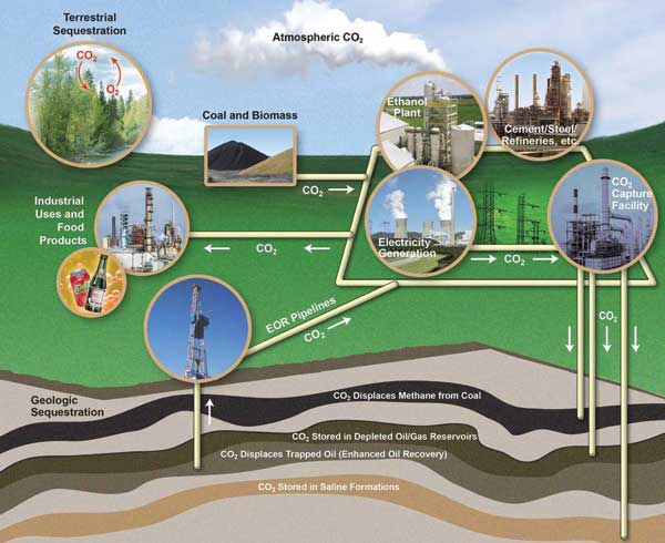
Worldwide carbon dioxide (CO2) emissions from human activity have increased from an insignificant level two centuries ago to more than 33 billion tons annually. At the same time, CO2 concentrations in the atmosphere have increased from 280 to 384 parts per million (IPCC, 2007). To curb these trends, scientists are studying the feasibility of capturing and sequestering, or storing, CO2 (fig. 1).
Figure 1--The carbon capture and storage process showing major pathways for geologic and terrestrial storage. Image adapted from U.S. DOE, 2007a.
One type of sequestration that may be viable, particularly in Kansas, is storing CO2 in deep underground rock formations, or geologic sequestration. This Public Information Circular provides background about geologic sequestration, the issues it raises, and potential locations in Kansas that might be amenable to carbon capture and sequestration. Terms shown in bold are defined in the glossary at the end.
Carbon dioxide (CO2), a colorless, odorless gas, is a natural and critical component of the atmosphere. It is given off through various natural and human processes. Among the most common sources of CO2 from human activity are fossil fuels, such as oil, gas, and coal, which are burned for transportation and power generation. CO2 is one of several greenhouse gases that are essential to maintaining life-sustaining temperatures on earth, but too much CO2 in the atmosphere could have a detrimental impact on the environment. Greenhouse gases allow heat from the sun to penetrate the earth's atmosphere but do not allow it to escape back into outer space. Though some scientists disagree about the nature and degree of climate change, there is a general consensus that increased greenhouse gases can contribute to increased temperatures and other changes in regional climate patterns. CO2 is of particular concern because it is increasingly produced through human activities. If current trends continue, the United States will emit 6.8 billion tons of CO2 by 2030, a 16% increase over 2006; Kansas CO2 emissions would be 89.5 million tons by 2030 (U.S. DOE, 2008).
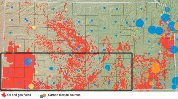
In Kansas, coal-fired electrical power plants, refineries, cement plants, and ethanol plants are the most common stationary sources of CO2 (fig. 2). Unlike emissions from non-stationary sources such as vehicle exhaust, CO2 from stationary sources can be captured for various uses, such as in food products and as dry ice. CO2 produced from many Kansas stationary sources, however, is impure--mixed with other gases--making it harder to use. The technology to isolate and capture CO2 from these sources is expensive, energy intensive, and undeveloped for large-scale applications. Currently, CO2 is only captured in Kansas at a few facilities that produce high-purity CO2. However, work is underway to reduce costs and energy requirements to make the isolation of CO2 from impure sources feasible on a commercial scale.
Figure 2--Documented stationary sources of CO2 and evaluated potential geological storage sites. Stationary sources include power-generation facilities, refineries, cement kilns, and ethanol plants. Black box outlines the area that the KGS and partners are studying for potential storage of CO2. Map created from NatCarb (2008) database.
Using energy more efficiently to reduce our reliance on fossil fuel combustion is one way to manage CO2. Promoting low-carbon and carbon-free fuels and technologies, such as geothermal power, hydropower, nuclear power, solar energy, wind power, and biomass fuels, is another. A third strategy is to manage CO2 through carbon storage sites sometimes referred to as "sinks." Some carbon dioxide sinks, such as oceans, plants, trees, and other photosynthetic organisms, are a natural part of the earth's carbon cycle.
Sequestration, the deliberate removal of CO2 from the atmosphere so that it can be safely contained, involves artificially storing the CO2 in such sources as water, vegetation, or geologic reservoirs in underground rocks (fig. 1). The entire process of capturing and sequestering CO2 is sometimes referred to as carbon capture and storage, or CCS. Several types of sequestration are being studied. One method under consideration is the injection of liquid-like CO2 deep into ocean water at depths greater than 3,300 ft (1,000 m). However, this might cause ocean acidification and long-term contamination. Another possibility is terrestrial sequestration. Trees, grasses, and other types of vegetation would be planted to remove CO2 from the air through photosynthesis. Carbon extracted from the CO2 would be incorporated into the plant biomass or stored in the soil. Terrestrial sequestration, however, has volume limitations. An estimated 220,000 acres of plants could be required to offset emissions from one average-sized power plant (Newell and Stavins, 2000). Geologic sequestration, described below, is a third option.
Geologic sequestration, injecting CO2 into underground rocks for secure contaiment, is efficient at depths greater than 2,400 ft (about 800 m). CO2 increases in density and becomes a supercritical fluid under the great pressures that naturally exist at those depths. Supercritical fluids take up less space and diffuse more easily through the pore spaces in rock formations than either gases or ordinary liquids. Five types of geologic formations considered the most likely candidates for geologic sequestration are
Geologic storage of CO2 has been underway for more than a decade with projects in Norway and Algeria and a joint U.S.-Canadian effort at the Dakota Gasification facility in North Dakota and the Weyburn field in Saskatchewan. These enterprises have provided significant data and experience with a variety of natural reservoirs. Numerous field projects in the U.S. and Canada are being developed in saline aquifers, oil reservoirs, and coal seams through the U.S. Department of Energy's Regional Carbon Sequestration Partnerships (U.S. DOE, 2007b), regional partnerships between private companies, universities, and governmental agencies. Thus far, no evidence suggests significant volumes of CO2 have migrated out of the confining reservoirs, indicating that long-term storage is feasible.
In Kansas, geologic sequestration of CO2 may be possible in all five of the geologic formations: deep saline aquifers, coal seams, oil and natural gas reservoirs, oil- and gas-rich organic shales, and basalt (the most problematic because no one knows how much CO2 the ancient rock--deeply buried in parts of Kansas--can hold). Altogether, researchers estimate Kansas has at least 2.7 to 5.4 billion tons of potential geologic sequestration space, enough to hold almost 70 years worth of the state's stationary CO2 production.
Saline aquifers could potentially store large amounts of CO2 in Kansas. The highly saline water is not usable for other purposes and would dissolve the CO2. The Arbuckle Group, a series of rock layers found only in the subsurface in Kansas, is a prospective environment for CO2 sequestration. Consisting mainly of dolomite, the sedimentary strata of the Arbuckle Group were deposited about 480 million years ago during the Cambrian and Ordovician periods of geologic history. They are found at depths ranging from less than 250 ft (75 m) in southeast Kansas to 8,000 ft (2,500 m) in southwest Kansas. In parts of the state, large amounts of oil have been produced from rocks in the Arbuckle Group. Brine from thousands of oil wells has already been successfully placed in the Arbuckle and other aquifers, indicating the aquifers might safely contain CO2 as well (Carr et al., 2005).
Sequestering CO2 in unmineable coal beds would remove it from the atmosphere and might also aid in the recovery of natural gas from Kansas coal beds, an important source of the gas (Sawin and Brady, 2001). In 2009 Kansas produced 42 billion cubic feet of coal-related gas, much of it from the Cherokee basin in the southeast. Although this gas is sometimes referred to as coalbed methane, it includes constituents other than methane.
Scientists at the Kansas Geological Survey (KGS) are studying ways to use gas high in CO2 emitted from cement plants and commercial landfills to enhance natural gas production from coal. They are investigating the practicality of injecting CO2 into subsurface coal beds to displace coalbed methane, which could then be processed and used. Such studies are in the preliminary stages, and the feasibility of using CO2 to produce natural gas from coal will be determined only after taking many geologic and economic factors into account. Whether or not CO2 sequestration in coal seams could be used to successfully produce more natural gas, the coal could still be used to sequester CO2.
Another way to manage CO2, at least in the near term, would be to use it in the production of hard-to-recover oil from older fields. In the process known as enhanced oil recovery (EOR), CO2 could be injected to force out additional oil, a procedure that would also sequester much of the CO2. Even in Kansas fields that are declining after decades of production, significant amounts of oil remain trapped in the pore space of underground rocks. CO2 pumped into these reservoirs would dissolve into the oil and reduce the oil's viscosity, making it easier to recover (fig. 3). Small amounts of CO2 coming back to the surface with the oil could be captured and reinjected to help produce more oil. Much of the CO2, however, would remain trapped below ground. CO2 is already being used commercially and experimentally to enhance oil recovery in a number of locations in the country, most notably in west Texas.
Figure 3--Carbon dioxide flooding
To better understand the use of CO2 in enhanced oil recovery, a mature oil field in Russell County, Kansas, was flooded with CO2 starting in 2003. The KGS monitored the movement of the CO2 underground using a geophysical technique called seismic reflection. Oil production increased as a result, though the complexity of the subsurface formations made it difficult to predict the exact movement of the CO2 flood.
In addition, the KGS has received major funding from the U.S. Department of Energy to characterize the underground geology of large parts of south-central and southwestern Kansas (see fig. 2). This research is particularly focused on analyzing subsurface rocks and fluids, looking at their ability to store CO2. None of these projects involves actual injection of CO2 into the subsurface, but they are designed to provide data that could be used for potential CO2 sequestration projects, both in terms of enhanced oil recovery and deeper sequestration in the Arbuckle.
In Kansas, the suitability of CO2 for enhanced recovery will depend on oil prices, the nature of the state's oil and gas reservoirs, and the ready availability of CO2. Because the state has had a long history of oil production, a great deal is known about its subsurface geology and incredible amounts of geologic data are available. Many known oil reservoirs appear to be candidates for CO2 flooding. KGS scientists estimate that oil reservoirs in Kansas could produce between 400 and 900 million additional barrels of oil with the use of CO2 flooding (Byrnes, 2000). At the same time, the process would sequester significant quantities of CO2. However, concerns have been raised in the state about regulating CO2 enhanced oil recovery and whether the CO2 would be trapped in these reservoirs or move back to the surface over time. Because Kansas has long been drilled for oil and gas and some areas have been very densely drilled, concerns also exist that CO2 could move back to the surface through poorly plugged or long-forgotten wells.
A number of issues must be resolved before geologic sequestration can play a major role in CO2 management. The capture of CO2 from waste streams, such as smokestacks, requires considerable cost and energy and has only been tested on a small scale. Even if it could be efficiently captured, much CO2 would have to be transported to storage locations. This would likely require construction of an extensive pipeline network. To be pumped underground, the gas would have to be compressed and perhaps turned into liquid CO2. This would require additional energy, although it would also significantly reduce the volume of the gas, which would make less storage space necessary. Finally, a regulatory environment would have to be created to protect health, safety, and the environment for long periods. Storage locations, for example, would need to be regularly monitored for leaks.
In Kansas, sequestration needs to be studied in more detail to determine if oil and natural gas reservoirs and coal beds have the capacity to take and hold CO2. This is especially true in locations with long histories of oil and gas exploration where older, poorly plugged wells could provide avenues for CO2 to return to the surface. In addition, a variety of legal issues, such as ownership of the underground pore space used for sequestration, would need to be resolved, and a workforce would have to be developed. Ultimately, regulatory decisions, economics, and a well-defined environment for greenhouse gas management will highly influence any decisions concerning the feasibility of geologic sequestration. Determining its future will require much data collecting and analysis.
The success of geologic sequestration depends on the availability of information about the location of CO2 sources, such as power plants, cement plants, refineries, and fertilizer plants, and the amount of CO2 they produce. Information about potential sequestration sites and transportation needs, such as pipelines, also is necessary. With funding from the U.S. Department of Energy, the KGS worked with geologic institutions in other states across the U.S. and Canada to develop a database of available information (http://www.natcarb.org/) (Natcarb, 2008). A Carbon Sequestration Atlas of the United States and Canada was produced as a result of that project (U.S. DOE, 2010) and allows users to most efficiently match the sources, transportation methods, and potential sequestration locations for CO2.
Acknowledgments--Thanks to Robert Sawin, Shane Lyle, W. Lynn Watney, K. David Newell, William Harrison, Cathy Evans, and Brad Loveless for reading and commenting on this circular and to Nick Callaghan for creating the map in fig. 2.
Aquifer: Rock formation capable of holding and yielding large amounts of ground water, usually held in pore spaces between rock particles. Aquifers of saline water are potential locations for sequestering CO2.
Carbon capture and storage (CCS): Process of capturing CO2 from large stationary sources such as power plants and isolating it from the atmosphere.
Carbon dioxide (CO2): Compound composed of one atom of carbon bonded with two atoms of oxygen that is a gas at standard temperatures and pressures.
Carbon dioxide sink: A reservoir that takes CO2 in, as opposed to a source, which produces CO2. Natural sinks are oceans, plants, and other organisms. Artificial sinks include geologic reservoirs.
Coalbed methane (CBM): Methane produced from coal layers. Because gas from the coal contains other components besides methane, the more general term is coalbed natural gas.
Enhanced oil recovery (EOR): Methods of producing oil after primary and secondary methods of production have been used. Primary production involves using natural underground pressures or pumping; in Kansas, secondary production generally refers to flooding underground oil reservoirs with water to produce more oil. Flooding with CO2 is a form of EOR.
Greenhouse gases: Gases that trap heat in the atmosphere and thus are often blamed for higher temperatures. The most abundant are water vapor, carbon dioxide, methane, nitrous oxide, and ozone.
Reservoir: As used herein, a natural underground formation that holds a liquid, such as oil or water. In Kansas, reservoirs generally hold oil or water in the pore space between rock particles.
Supercritical fluids: Highly compressed gases that take on many of the properties of both gases and liquids.
Byrnes, A. P., 2000, Field demonstration of CO2 miscible flooding in the Lansing-Kansas City formation, central Kansas: Presentation to DOE-NPTO Contractors Conference, Denver, June 29, 2000. [available online]
Carr, T. R., Merriam, D. F., and Bartley, J. D., 2005, Use of relational databases to evaluate regional petroleum accumulation, ground-water flow, and CO2 sequestration in Kansas: American Association of Petroleum Geologists, Bulletin, v. 89, no. 12, p. 1,607-1,627.
Intergovernmental Panel on Climate Change (IPCC), 2007: Climate Change 2007--The Physical Science Basis, Summary for Policymakers, 18 p., http://www.ipcc.ch/ipccreports/ar4-wg1.htm (verified November 2008).
Natcarb, 2008, National carbon sequestration database and geographic information system, http://www.natcarb.org/index_nc.html (verified October 2008).
Newell, R. G., and Stavins, R. N., 2000, Climate change and forest sinks--Factors affecting the costs of carbon sequestration: Journal of Environmental Economics and Management, v. 40, no. 3, p. 211-235.
Sawin, R. S., and Brady, L. L., 2001, Natural gas from coal in eastern Kansas: Kansas Geological Survey, Public Information Circular 19, 4 p. [available online]
U.S. Department of Energy (DOE), 2010, 2010 carbon sequestration atlas of the United States and Canada: U.S. Department of Energy, NETL, Atlas III, http://www.netl.doe.gov/technologies/carbon_seq/refshelf/atlasIII/index.html (verified January 2011).
U.S. Department of Energy (DOE), 2008, Annual energy outlook 2008 with projections to 2030: U.S. DOE Energy Information Administration, Report #DOE/EIA 0383, http://www.eia.doe.gov/oiaf/aeo/emission.html (verified October 2008).
U.S. Department of Energy (DOE), 2007a, Carbon sequestration atlas of the United States and Canada: U.S. Department of Energy, Office of Fossil Energy, National Energy Technology Laboratory, http://www.netl.doe.gov/technologies/carbon_seq/refshelf/atlas (verified November 2008).
U.S. Department of Energy (DOE), 2007b, Carbon sequestration technology roadmap and program plan: U.S. Department of Energy, Office of Fossil Energy, National Energy Technology Laboratory, 47 p.
![]()
![]()
![]()
Kansas Geological Survey, Public Outreach
Comments to webadmin@kgs.ku.edu
Revised version of March 2011
http://www.kgs.ku.edu/Publications/PIC/pic27.html