Kansas Geological Survey, Irrigation Series 2, originally published in 1976
Originally published in 1976 as Kansas Geological Survey Irrigation Series 2. This publication is also available as an Acrobat PDF file (1.3 MB). The plates are available separately.
Unconsolidated deposits of sand, silt, clay, and gravel compose the principal aquifer in Greeley and Wichita counties. The deposits are as much as 300 feet (91 m) thick, of which as much as 145 feet (44 m) is saturated.
In 1972, there were about 1,040 large-capacity wells-yielding 100 gallons per minute (6.3 L/s) or more-in the counties, mostly for irrigation supplies. The wells yield as much as 2,000 gallons per minute (130 L/s). Withdrawals of ground water average about 220,000 acre-feet (270 hm3) annually.
Water levels have declined in parts of the area where large-capacity wells are concentrated, resulting in as much as 60-percent reduction in saturated thickness. Water-level declines during 1948-72 ranged from less than 10 to about 55 feet (3-17 m). The largest decline, about 55 feet (17 m), has occurred near Leoti, in central Wichita County. As of January 1972, about 5 million acre-feet (6,000 hm3) of ground water were in storage in Greeley and Wichita counties; however, only about 70 percent of this amount is considered to be available for pumping.
The water from the unconsolidated aquifer is a mixed chemical type in which calcium, sodium, and bicarbonate are the principal constituents. Generally, the water is suitable for all common domestic, stock, and irrigation uses.
Price increases for grain in 1973 and absence of acreage controls probably will encourage additional development of ground water for irrigation. Increased withdrawals will, however, accelerate the rate of water-level decline and reduction in ground-water storage. Increased water-level declines will be accompanied in most of the area by noticeable decreases in well yields. Any additional increase in the rate of withdrawal in areas where saturated thickness has declined about 40 percent or more may significantly shorten the economic life of the aquifer. Additional development in these areas should be considered with regard to increasing pumping costs and decreasing well yields. Development of the ground-water resource could be managed in several ways. The formation of Kansas Ground-Water Management District Number 1 provides a means by which local water users can decide on various management alternatives that would affect the future of their irrigation supply.
This report presents information on the groundwater resources of Greeley and Wichita counties. The study began in 1971 as part of a cooperative program between the Kansas Geological Survey and the U.S. Geological Survey with data and support provided by the Division of Water Resources of the Kansas State Board of Agriculture and the Division of Environment of the Kansas Department of Health and Environment.
The objectives in the study were to determine (1) the amount and availability of ground water, (2) the chemical quality and suitability of the water for common uses, (3) the extent and effects of ground-water development, and (4) the future outlook for irrigation.
Data for this study, obtained in 1971 and 1972, were compared with data from previous investigations by Prescott and others (1954) and by Bradley and Johnson (1957). Data collection consisted of locating all large-capacity wells; measuring water levels, well discharges, and power-consumption; drilling test holes to correlate lithology and hydraulic conductivity; determining hydraulic properties by aquifer tests; and obtaining water samples for chemical analysis.
Greeley County is on the western border of Kansas, and Wichita County joins Greeley County on the east. The two counties are located midway between the north and south boundaries of the State (fig. 1). Greeley and Wichita counties cover an area of about 1,510 square miles (3,910 km2) lying within the High Plains section of the Great Plains physiographic province. The area is characterized as a flat to gently rolling upland plain with a few shallow valleys and many undrained depressions. The land surface slopes gradually eastward at about 15 feet per mile (2.8 m/km) from an altitude of about 3,900 feet (1,190 m) at the State line to slightly less than 3,100 feet (940 m) at the Wichita-Scott County line.
Figure 1--Location of report area and system of numbering wells.
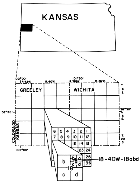
The well and test-hole numbers used in this report give the location of wells according to the Bureau of Land Management's system of land subdivision. In this system, the first set of digits of a well number indicates the township; the second set, the range east or west of the Sixth Principal Meridian; and the third set, the section in which the well is located (fig. 1). The first letter denotes the quarter section or 160-acre (65-hm2) tract; the second letter, the quarter-quarter section or 40-acre (16-hm2) tract; the third letter, the quarter-quarter-quarter section or 10-acre (4-hm2) tract. The 160-acre, 40-acre, and 10-acre tracts are designated a, b, c, and d in a counterclockwise direction beginning in the northeast quadrant. As an example, well 18-40W-18abd is in the SE NW NE sec. 18, T. 18 S., R. 40 W. Where two or more wells are located within a 10-acre tract, wells are numbered serially according to the order in which they were inventoried.
Two aquifers underlie Greeley and Wichita counties. The upper aquifer consisting chiefly of sand and gravel in the Ogallala Formation is the principal aquifer in western Kansas. The lower aquifer consisting chiefly of sandstone in undifferentiated rocks of Late Jurassic and Early Cretaceous age is important in localities where adequate supplies are not available from shallow deposits. The aquifers are separated by as much as 900 feet (270 m) of rocks that do not yield significant amounts of water to wells in the study area. A general description of the geologic units and their water-yielding characteristics is given in table 1.
Table 1--Generalized section of geologic units. [The classification and nomenclature of the rock units used in this report are those of the Kansas Geological Survey and differ somewhat from those of the U.S. Geological Survey. Yield in gpm (gallons per minute) multiplied by 0.06309 equivalent to L/s (liters per second).]
| System | Series | Geologic Unit | Thickness, in feet |
Physical Character | Water Supply |
|---|---|---|---|---|---|
| Quaternary | Pleistocene | Loess and dune sand |
0-30 | Silt and fine sand, mostly eolian. Mantles most of the upland and masks much of the valley walls. | Most of the deposits are above water table. Where saturated, locally yields 5 to 10 gpm to wells. |
| Alluvium | 0-30 | Stream-laid deposits ranging from sand and gravel to silt and clay. Occurs along principal stream valleys. | Generally above the water table. Where saturated, locally yields about 250 gpm to irrigation wells. | ||
| Tertiary | Pliocene | Ogallala Formation |
0-300 | Sand, gravel, silt, clay, and caliche, commonly unconsolidated. Locally cemented by calcium carbonate (lime) or silica (opal) into mortar beds. Also contains thin freshwater limestone beds. | Principal aquifer in the area. Yields to irrigation wells range from 100 to 2,000 gpm. |
| Cretaceous | Upper Cretaceous |
Pierre Shale |
0-50 | Dark-gray fissile shale. In the subsurface, the upper few feet locally is a yellow weathered zone, underlies only the extreme northwest corner of Greeley County. | Not known to yield significant amounts of water to wells. |
| Niobrara Chalk |
150-410 | Upper unit (Smoky Hill Chalk Member) consists of yellow to orange-yellow chalk and light- to dark-gray beds of chalky shale that locally weathers to ochre-yellow. Lower unit (Fort Hays Limestone Member) consists of a white to yellow massive chalky limestone; contains thin beds of dark-gray to brownish-gray chalky shale. | Not known to yield significant amounts of water to wells in Greeley and Wichita counties, but yields as much as 1,000 gpm to wells in southeastern Scott County where the rocks have been fractured. | ||
| Carlile Shale |
200-295 | Upper part consists of a dark-gray to blue-black noncalcareous to slightly calcareous shale that locally is interbedded with calcareous silty very fine sandstone. Lower part consists of very calcareous dark-gray shale and thin interbedded limestone. | Sandstone in upper part may yield 5 to 10 gpm to wells. | ||
| Greenhorn Limestone |
70-160 | Alternating light- to dark-gray thin-bedded chalky limestone and calcareous shale. Contains layers of bentonite. | Not known to yield Significant amounts of water to wells. | ||
| Graneros Shale |
25-60 | Dark-gray calcareous shale interbedded with black noncalcareous shale. Contains thin beds of bentonite, gray limestone, and fine-grained silty sandstone. | Not known to yield significant amounts of water to wells. | ||
| Lower Cretaceous |
Undifferentiated rocks |
300-500 | Upper unit (Dakota Formation)--brown to gray fine- to medium-grained sandstone interbedded with gray sandy shale and varicolored shale. Middle unit (Kiowa Formation )--dark-gray to black shale interbedded with tan and gray sandstone. Lower unit (Cheyenne Sandstone)--gray and brown fine- to medium-grained sandstone interbedded with dark-gray shale. | Yields of 30 to 300 gpm may be available to wells completed in sandstone beds. No irrigation wells currently (1973) withdraw water from these rocks within the report area. | |
| Triassic | Upper Jurassic |
Undifferentiated rocks |
0-200 | Gray, noncalcareous shale, interbedded with gray-green and blue-green calcareous shale. Contains fine-grained silty sandstone, and thin limestone beds. | The sandstone beds, although untested, may be a potential aquifer. |
The unconsolidated aquifer in Greeley and Wichita counties is comprised of the Ogallala Formation of Pliocene age and alluvium of Pleistocene age. The Ogallala consists primarily of alluvium deposited by shifting meandering streams. The resulting heterogeneous mixture of sand, gravel, silt, and clay contains large quantities of ground water, but a specific water-yielding sand or gravel deposit can be traced for only a short distance. A common sequence of the deposits is shown on a typical electric log in figure 2.
Figure 2--Typical electric log of the unconsolidated aquifer in Greeley and Wichita counties.
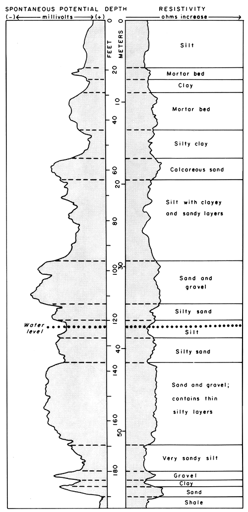
"Mortar beds", which commonly consist of sand and gravel cemented by caliche or silica, are widespread and are typical of the Ogallala. A thin freshwater limestone is found locally in the formation. The Ogallala Formation ranges in thickness from a few feet to as much as 300 feet (91 m) in Greeley and Wichita counties.
Alluvium of Pleistocene age forms part of the unconsolidated aquifer in the eastern reaches of Ladder, Whitewoman, and Sand Creeks. The alluvium, which consists of material reworked from the Ogallala Formation and Pleistocene loess deposits, is as much as 30 feet (9 m ) thick and generally contains less silt and clay than the Ogallala.
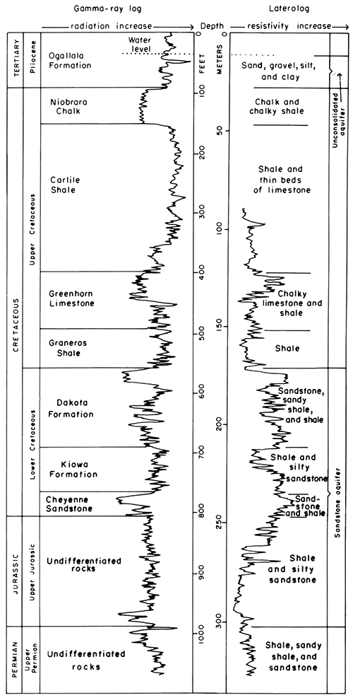
The sandstone aquifer, as defined here, includes all the water-yielding units in rocks of Late Jurassic and Early Cretaceous age in Greeley and Wichita counties. The rocks consist mostly of interbedded shale and sandstone (table 1). A gamma-ray and laterolog (fig. 3) illustrate a typical sequence of rock units. Only the major sandstone units will yield significant amounts of water to wells.
Figure 3--Typical gamma-ray log and laterolog (focused resistivity) in Greeley and Wichita counties.
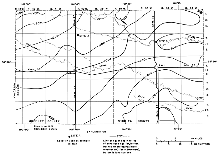
Thickness of the sandstone aquifer (shale and sandstone) ranges from about 400 to 550 feet (120 to 170 m) in the counties (fig. 4). The aquifer is thinnest in southeastern Greeley County and thickest in south-central Wichita County. Depth to the top of the sandstone aquifer (fig. 5) ranges from about 600 feet (180 m) in the southeastern part of the area to about 1,500 feet (460 m) in the northwestern part.
Figure 4--Generalized thickness of the sandstone aquifer.
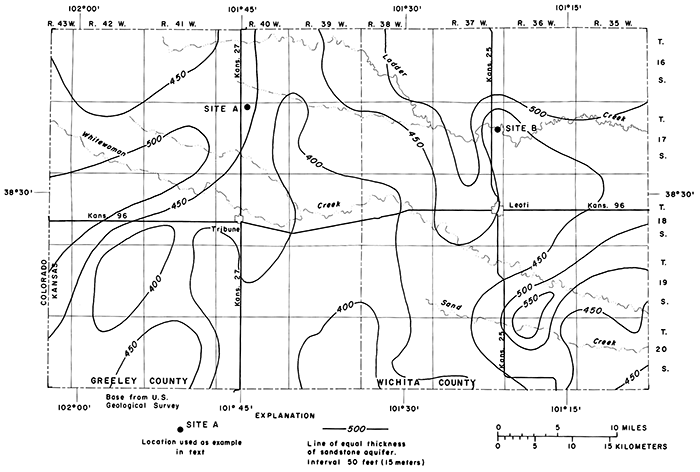
Figure 5--Generalized depth to the top of the sandstone aquifer.
Two sites will be referred to throughout this report to illustrate how information can be interpreted from maps like those on figures 4 and 5. Site A is about 9 miles (14 km) north of Tribune in the center of sec. 4, T. 17 S., R. 40 W. Site B is about 6 miles (10 km) north of Leoti in the center of sec. 13, T. 17 S., R. 37 W.
Inspection of figure 4 shows that Site A is close to the 450-foot line of equal thickness of the sandstone aquifer. Interpreting between the 450- and 500-foot lines, the aquifer thickness at Site A is estimated to be about 460 feet (140 m). Site B also is close to the 450-foot line, but, because it is between the 400- and 450-foot lines, the aquifer thickness here is estimated to be about 430 feet (130 m).
Figure 5 is interpreted in the same way except that estimates of values are made between lines of equal depth to the top of the sandstone aquifer. At Site A the top of the aquifer is estimated to be at a depth of about 1,160 feet (350 m) and at Site B about 910 feet (2S0 m). The two sites, therefore, are underlain by about the same thickness of sandstone aquifer, and the depth that wells would have to be drilled to reach the aquifer at Site A is about 250 feet (SO m) greater than at Site B.
The sandstone aquifer in the two-county area is relatively untested, however, data from adjacent counties indicate that wells in loosely cemented sandstones may yield from 30 to 300 gpm (2 to 19 L/s) of water for municipal, domestic, or stock supplies. Available data also indicate that the water is of the sodium bicarbonate type with a high salinity hazard and a very high sodium hazard for irrigation use.
Because all the known water supplies for municipal, industrial, and irrigation use in Greeley and Wichita counties are obtained from wells in the unconsolidated aquifer, the remainder of this report is concerned principally with information about water related to that aquifer.
Inflow (recharge) to the unconsolidated aquifer in Greeley and Wichita counties is derived primarily from precipitation on the area and from ground-water underflow from neighboring areas to the west and north. Outflow (discharge) from the aquifer is by evapotranspiration, underflow to the east, and withdrawals from wells. When long periods of time are considered, inflow to the reservoir equals outflow plus or minus the change in storage.
The major components of this general equation are estimated for 1971-72 using average values as discussed in the following sections.
| Acre-feet per year1 | ||
|---|---|---|
| Inflow | ||
| Recharge from precipitation2 | ||
| Irrigated acres | 18,000 | |
| Nonirrigated acres | 4,000 | |
| Subsurface inflow | 5,000 | |
| Total | 27,000 | |
| Outflow | ||
| Net withdrawal from wells | 176,000 | |
| Subsurface outflow | 9,000 | |
| Total | 185,000 | |
| Change in storage | ||
| Total (Decrease) | 158,000 | |
| 1. Acre-feet per year times 1.233 x 10⁻³ equals cubic hectometers per year. 2. Based on an average April-to-September precipitation of 13.5 inches (34 cm). |
||
Most precipitation in Greeley and Wichita counties evaporates or is consumed or transpired by plants. According to the National 'Weather Service, normal annual precipitation at Tribune is 16.98 inches (43 cm) and at Leoti is 18.63 inches (47 cm). Average annual precipitation in the two-county area is about 18.0 inches (46 cm); average precipitation during the April to September growing season is about 13.5 inches (34 cm). Average potential evaporation during April-September is 61.97 inches (157 cm ) according to a 38-year record at the Tribune Experiment Station. The potential evaporation, therefore, far exceeds precipitation.
Only following significant storms does the infiltration of precipitation exceed the moisture-retention capability of the soil and permit water to percolate below the root zone. Prescott and others (1954) estimated that about 0.1 inch (0.3 cm) of precipitation reaches the water table annually in Greeley and Wichita counties. Estimates from subsequent studies in adjacent counties are somewhat greater.
As reported in the Finney County study (Meyer and others, 1970), recharge from precipitation on irrigated areas is Significantly greater than from precipitation elsewhere. In irrigated areas, it is common practice to pump sufficient ground water to maintain soil moisture for crop use and for leaching of salts. Therefore, precipitation that is in excess of the amount required to overcome soil-moisture deficiencies can percolate to the water table. In nonirrigated areas, precipitation supplies all the soil moisture utilized by vegetation, and excess water for deep percolation is available only during periods of abnormally high rainfall. For this report, estimates of inflow from precipitation are assumed to be 10 percent of the precipitation on irrigated land during the growing season (April-September) and 1 percent of the precipitation on nonirrigated land.
About 864 square miles (2,200 km2) of Greeley and Wichita counties are underlain by a significant amount of saturated material in the unconsolidated aquifer. Of this area, about 163,000 acres (66,000 hm2) are irrigated and 390,000 acres (158,000 hm2) are nonirrigated. Recharge to the aquifer from the average 13.5 inches (34 cm ) of precipitation during the growing season amounts to about 18,000 acre-feet (22 hm3) annually in the irrigated area and about 4,000 acre-feet (5 hm3) annually in the nonirrigated area.
Runoff of precipitation to streams also is a source of recharge to the unconsolidated aquifer in Greeley and Wichita counties. The streams have sandy channels, particularly in their upper reaches, and are underlain by permeable deposits of sand and gravel. Water infiltrates the channel sides and bottom during periods of flow after heavy rains, and much of this water percolates to the water table. Some of the runoff that collects in shallow depressions on the land surface also percolates to the water table and recharges the ground-water reservoir. However, the bottoms of the depressions are filled with clayey soil that retards infiltration. Consequently, most of the water evaporates. The amount of annual recharge from streamflow losses and from runoff into surface depressions is considered to be included with the total estimate of recharge from precipitation.
On July 10, 1972, a peak discharge of 5,600 ft3/s (160 m3/s) passed the U.S. Geological Survey's streamflow gaging station at the highway 96 bridge over Whitewoman Creek, 7 1/4 miles (12 km) west of Leoti. Flow started at 10:00 PM July 9 and continued until 10:00 AM July 11. A total of 3,050 acre-feet (4 hm3) of water passed the gage. A temporary gage established 58 stream miles downstream at the highway 83 crossing of Whitewoman Creek, which is 314 miles (6 km) south of Scott City (Scott County), recorded a total flow of 500 acre-feet (0.6 hm3) that passed the gage. The loss of 2,550 acre-feet (3 hm3) represents a loss of at least 44 acre-feet per mile (0.03 hm3/km) in the reach. Actual loss per mile is unknown because of unmeasured tributary inflow from Sand Creek.
The average annual flow of Whitewoman Creek at the gaging station near Leoti, computed for 5 years of record, is 964 acre-feet (1.2 hm3). If this volume of water passed the Leoti station as a single runoff event, all the water would infiltrate the channel within about 22 miles (35 km) below the gage, which is well within the borders of Wichita County.
The amount of recharge to the unconsolidated aquifer in Greeley and Wichita counties by underflow of ground water from adjacent areas to the west and north is unknown, but Prescott and others (1954) estimated that it is about 5,000 acre-feet (6 hm3) annually. This estimate is accepted for this report also.
Outflow from the unconsolidated aquifer by evapotranspiration is negligible in Greeley and Wichita counties because the water table in most of the area is too far below land surface to be affected by evaporation and transpiration. Some phreatophytes grow along Ladder Creek, but the stream has no flow much of the time. None of the streams in the counties discharge water from the ground-water reservoir.
Outflow from the unconsolidated aquifer by ground-water underflow to the east of the counties can be estimated using the formula:
Q = KIA
where
(Q) = quantity of water;
(K) = hydraulic conductivity of the aquifer;
(I) = hydraulic gradient;
(A) = cross-sectional area through which the ground water moves.
Hydraulic conductivity is determined from aquifer tests (table 2) and analyses of test-hole data. Along the east line of Wichita County the hydraulic conductivity averages 65 ft/day (20 m/day). The hydraulic gradient, determined from the slope of the water table, averages 15.5 feet per mile (3 m/km) across the east line of the county. The cross-sectional area along the line, determined from the saturated-thickness map (pl. 1), amounts to about 5.8 million square feet (0.54 X 10⁶ m2). Using these values, the average annual discharge from the ground-water reservoir in Greeley and Wichita counties by underflow to the east is about 9,000 acre-feet (11 hm3):
Withdrawals from wells far exceed all other discharge from the unconsolidated aquifer in Greeley and Wichita counties. In September 1972 there were 1,037 large-capacity wells (irrigation, municipal, and industrial), 222 in Greeley County and 815 in Wichita County. The amount of water pumped from the wells can be estimated by determining the amount of fuel required to pump a given volume of water and multiplying by the total fuel consumed. Fuel consumption usually is known because fuel generally is metered. A tabulation of the number of wells and types of power used in the counties is given below.
| Power type | Number of Wells | |||
|---|---|---|---|---|
| Greeley County | Wichita County | Total | Percent | |
| Natural gas | 162 | 672 | 834 | 80.4 |
| Electricity | 42 | 105 | 147 | 14.2 |
| LPG | 12 | 30 | 42 | 4.1 |
| Diesel | 5 | 8 | 13 | 1.3 |
| Gasoline | 1 | 0 | 1 | |
A factor relating the consumption of natural gas to the amount of water pumped can be determined from the equation:
Kg = [(1.955 X 10⁷) VPg] / Qtg
where
Kg = cubic feet of natural gas to pump 1 acre-foot of water;
V = cubic feet of natural gas consumed in tg seconds;
Pg = pressure factor (a function of atmospheric pressure, altitude above mean sea level, and line pressure);
Q = pump discharge, in gallons per minute;
tg = time, in seconds, to consume V volume of natural gas;
and (1.955 X 10⁷) is a constant needed to convert the parameters into consistent units.
Measurements of the parameters for 38 wells in the counties (Stullken and others, 1974) indicate that values of Kg range from 4,100 to 20,600 ft3/ acre-ft (9.4 X 10⁴ to 47.3 X 10⁴ m3/hm3). The median value of Kg for the 38 wells was 7,600 ft3/acre-ft (17.4 X 10⁴ m3/hm3).
Similar computations can be made to relate consumption of other fuels and of electricity to the amount of water pumped, but the data needed are not available in Greeley and Wichita counties. Records from the Kansas-Nebraska Natural Gas Company, Inc. show that 1,543,119,700 ft3 (43.7 X 10⁶ m3) of natural gas was supplied to irrigation wells in the counties in 1971, and 1,234,098,100 ft3 (34.9 X 10⁶ m3) was supplied in 1972. Using these values and the median power factor (Kg) determined above, about 200,000 acre-feet (247 hm3) of water was pumped from natural-gas powered wells in 1971 and about 160,000 acre-feet (197 hm3) in 1972.
The tabulation of number of wells and type of power used shows that power for about 80 percent of the large-capacity wells in Greeley and Wichita counties is supplied by natural gas. Assuming that 80 percent of the wells produce 80 percent of the water, total withdrawals by large-capacity wells in the counties were about 250,000 acre-feet (308 hm3) in 1971, and about 200,000 acre-feet (247 hm3) in 1972. The lesser amount of water pumped in 1972 is attributed to above-normal precipitation during the year. Average annual withdrawals of ground water in Greeley and Wichita counties are about 220,000 acre-feet (271 hm3):
Some of the ground water withdrawn by wells and applied for irrigation is "lost" to deep percolation. Using figures experimentally derived by Meyers and others (1970) for irrigated land in Finney County, about 20 percent of the water applied to irrigated land in Greeley and Wichita counties may be returned to the aquifer. Using the average annual withdrawal by wells of 220,000 acre-feet (271 hm3), it is estimated that about 44,000 acre-feet (54 hm3) returns to the ground-water reservoir. Thus, the net withdrawal of water by wells from the reservoir is estimated to be 176,000 acre-feet (217 hm3) annually.
The unconsolidated aquifer forms a ground-water reservoir that contains, at any given time, a certain amount of water in storage. The amount of water stored in an area can be estimated by determining the amount (volume) of aquifer material in the area that is saturated and multiplying by the specific yield of the aquifer.
The amount of saturated aquifer material in Greeley and Wichita counties in 1972 has been determined by constructing a series of maps. The configuration of the top of the saturated material (water-table configuration) is shown on plate 1, which was constructed from depth-to-water measurements in 192 wells in January 1972. Plate 2, which shows the configuration of the base of the saturated material (bedrock configuration), was constructed by interpreting logs of test holes and wells. By comparing the water-table and bedrock maps, the saturated thickness of the unconsolidated aquifer in January 1972 may be interpreted as shown on plate 1.
The area in which water-table contours and lines of equal saturated thickness are shown on plate 1, and the area used in calculations, represents the main body of the unconsolidated aquifer. Outside of this area, saturated thickness of unconsolidated deposits generally is no more than a few feet, except in isolated channels in the bedrock. Within the mapped area, saturated thickness is as much as 145 feet (44 m).
The water-table configuration (pl. 1) indicates that ground water in the unconsolidated aquifer generally moves eastward. The movement is downgradient and generally perpendicular to the contours. Near Site A (center sec. 4, T. 17 S., R. 40 W.), ground water moves toward a depression in the water table where the effect of withdrawals from several closely spaced wells was still evident in January 1972, several months after pumping during the previous irrigation season had ceased. At Site B (center sec. 13, T. 17 S., R. 37 W.) the ground-water movement is easterly, and water levels either have recovered or were not affected significantly by pumping during the previous irrigation season.
The bedrock configuration (pl. 2) can be interpreted in the same manner as a topographic map that shows contours of land-surface altitude. In general, the bedrock surface slopes easterly from altitudes of about 3,BOO feet (1,160 m ) in western Greeley County to about 3,000 feet (910 m) in eastern Wichita County. At Site A the bedrock surface is a gentle "hillside" between a bedrock ridge to the north and a bedrock valley (buried channel) to the south. About four miles (6 km) south of Site A, hachured contours indicate a broad, shallow sink or closed basin on the bedrock surface. Site B is underlain by a relatively flat, easterly sloping bedrock surface. Buried hills and valleys on the bedrock surface are a primary control on thickness of the unconsolidated aquifer.
A significant difference in the ground-water situation between Sites A and B can be seen on plate 1. Interpreting from the contours that show equal saturated thickness, Site A is underlain by about 20 feet (6 m) of saturated material in the unconsolidated aquifer. Site B, however, is underlain by about 90 feet (27 m ) of saturated aquifer material. If the type of saturated material at the two sites is approximately the same, a well at Site B would have a much larger potential yield than a well at Site A.
Water in the unconsolidated aquifer generally is considered to be unconfined, as shown by the data in the summary of aquifer tests given in table 2. Storage coefficients of 0.05 to 0.30 generally indicate unconfined conditions; 0.001 to 0.05 indicate semiconfined conditions (Ferris and others, 1962). The lithology of the aquifer at wells 16-41W-17ccc and 17-38W-35daa suggest that the storage-coefficient values probably are low owing to the short duration of the tests. If the tests had been of longer duration, the values probably would have been similar to the storage coefficient of 0.18 determined from the test at well 18-36W-5dbb. The lithology of the aquifer at well 17-39W-19dbb also suggests the aquifer is unconfined. The very low storage coefficient in this test is believed to result from limitations in the analysis where drawdowns in unconfined aquifers are large in relation to original saturated thicknesses (Stallman, 1965).
The test data and general lithology of the aquifer in Greeley and Wichita counties appear to be comparable to those in Finney County (Meyer and others, 1970) and in Lane and Scott Counties (Gutentag and Stullken, 1976). A specific yield of 0.15, as used in adjacent counties, is considered to be representative of the unconsolidated aquifer in Greeley and Wichita counties.
Local confined or semiconfined conditions are present within the aquifer, owing to the heterogeneous nature of the deposits. The confined conditions are often temporary and will revert to unconfined conditions when the water level is drawn below the local confining bed after long periods of pumping and when gravity drainage is initiated. The relation between confined and unconfined conditions in the aquifer is discussed later in this report.
The apparent radius of influence of a pumping well, as used in this report, is the distance at which the drawdown on the cone of depression is equal to 1 foot (0.3 m ). The apparent radius, given in table 2, is a theoretical value calculated for the duration of the test. Distances range from 350 feet (110 m) where the water is unconfined to 4,200 feet (1,280 m) where the water appears to be temporarily confined. This apparent radius of influence varies at any site with the rate and duration of pump age, areal variations of hydraulic conductivity, storage coefficient, and homogeneity of the aquifer.
Table 2--Summary of aquifer tests.
| Well number |
Transmissivity (ft2/day) |
Storage coefficient (dimensionless) |
Hydraulic conductivity (ft/day) |
Depth to water (feet) |
Saturated thickness (feet) |
Effective thickness (feet) |
Average discharge (gpm) |
Specific capacity (gpm/ft) |
Duration of test (min) |
Natural gas power factor (ft3/acre-ft)> |
Apparent radius of influence (feet) |
|---|---|---|---|---|---|---|---|---|---|---|---|
| 16-41W-17ccc | 9,500 | 0.09 | 144 | 155 | 74 | 66 | 1,250 | 38 | 960 | 5,400 | 400 |
| 17-38W-35daa | 5,700 | .08 | 100 | 121 | 69 | 67 | 950 | 32 | 960 | 4,900 | 350 |
| 17-39W-19dbb | 5,400 | .001 | 174 | 126 | 54 | 31 | 680 | 18 | 2,170 | 4,200 | |
| 18-36W-5dbb | 12,000 | .18 | 197 | 124 | 76 | 61 | 515 | 12 | 8,860 | 7,400 | 500 |
| English units are multiplied by conversion factors to obtain metric units as follows: feet X 0.3048 = meters; ft/day X 0.3048 = m/day, f2/day X 0.0929 = mi/day; gpm X 0.06309= L/s; gpm/ft X 0.207 = (L/s)m; and ft3/acre-ft X 22.97 = m3/hm3. |
|||||||||||
The amount of ground water stored in the aquifer was determined by planimetering the contoured areas of saturated thickness, shown on plate 1, multiplying by the average saturated thickness for that area, and multiplying again by the specific yield (0.15). The amount of ground water stored in the unconsolidated aquifer in Greeley and Wichita counties is estimated to be 5 million acre-feet (6,000 hm3) as of January 1972. Because of physical limitations of wells and pumps, hydraulic properties of the aquifer, and economic considerations of reduced well yields, only about 70 percent of the ground water in storage is considered to be available for pumping.
Results of chemical analyses of water samples from 21 selected wells in the unconsolidated aquifer in Greeley and Wichita counties are given in table 3. Results of additional analyses are listed in Stullken and others (1974). The results indicate that the water has a hardness of 160 to 300 mg/l and that it can be classed on the basis of predominant ions as a mixed chemical type in which calcium, sodium, and bicarbonate are the principal constituents. Generally the water is suitable for all the common domestic, stock, and irrigation uses. The water meets all the chemical standards for drinking water recommended by the Kansas Department of Health and Environment except for hardness and, locally, fluoride concentration. Chemical analyses do not indicate the sanitary quality of the water.
Table 3--Chemical analyses of water from selected wells in Greeley and Wichita counties. [Dissolved constituents and hardness given in milligrams per liter. Analyses by Kansas Department of Health and Environment.]
| Well number |
Well depth (feet) |
Date of col1ection |
Temp. (°C) |
Dissolved solids (residue at 180°C) |
Dissolved silica (SiO2) |
Iron (Fe) |
Dissolved manganese (Mn) |
Dissolved calcium (Ca) |
Dissolved magnesium (Mg) |
Dissolved sodium and potassium (Na + K) |
Bicarbonate (HCO3) |
Dissolved sulfate (SO4) |
Dissolved chloride (Cl) |
Dissolved fluoride (Fl) |
Dissolved nitrate (NO3) |
Hardness as CaCO3 | Specific conductance (micromhos at 25°C) |
pH (units) |
||
|---|---|---|---|---|---|---|---|---|---|---|---|---|---|---|---|---|---|---|---|---|
| Total | Carbonate | Noncarbonate | ||||||||||||||||||
| Unconsolidated aquifer | ||||||||||||||||||||
| 16-35W-20ccc | 189 | 6-19-1972 | 15.0 | 330 | 26 | 0.13 | 0.0 | 51 | 17 | 35 | 193 | 58 | 26 | 1.6 | 16 | 200 | 161 | 39 | 510 | 7.8 |
| 16-36W-21ccc | 205 | 6-22-1972 | 15.0 | 294 | 22 | .07 | .0 | 41 | 17 | 33 | 195 | 43 | 15 | 1.9 | 10 | 170 | 158 | 12 | 450 | 7.8 |
| 16-37W-36bbb | 6-19-1972 | 15.0 | 300 | 24 | .05 | .0 | 45 | 18 | 35 | 207 | 49 | 15 | 1.6 | 10 | 190 | 174 | 16 | 480 | 7.8 | |
| 16-38W-4ccb | 226 | 3-03-1972 | 266 | 29 | .15 | .0 | 38 | 16 | 29 | 195 | 34 | 11 | 1.2 | 4.2 | 160 | 159 | 1 | 420 | 7.8 | |
| 17-35W-27ccc | 210 | 4-19-1972 | 360 | 38 | .03 | .0 | 45 | 23 | 38 | 193 | 80 | 23 | 2.0 | 9.7 | 210 | 161 | 49 | 520 | 7.8 | |
| 17-36W-14dad | 6-22-1972 | 16.0 | 392 | 38 | .06 | .0 | 59 | 24 | 44 | 278 | 64 | 25 | 1.9 | 2.0 | 250 | 232 | 18 | 610 | 7.8 | |
| 17-37W-22ccc | 195 | 10-14-1971 | 346 | 45 | .03 | .0 | 46 | 20 | 37 | 190 | 66 | 21 | 1.7 | 9.3 | 200 | 165 | 35 | 500 | 8.0 | |
| 17-38W-21bbb | 165 | 3-02-1972 | 376 | 49 | .11 | .0 | 46 | 24 | 43 | 212 | 82 | 21 | 1.8 | 8.8 | 210 | 170 | 40 | 570 | 7.7 | |
| 18-35W-34abb | 143 | 3-02-1972 | 354 | 57 | .09 | .0 | 53 | 16 | 35 | 222 | 48 | 20 | 1.6 | 6.2 | 200 | 184 | 16 | 520 | 7.7 | |
| 18-36W-23bcd | 140 | 10-05-1971 | 258 | 44 | .05 | .0 | 40 | 15 | 25 | 185 | 27 | 13 | 1.6 | 9.7 | 160 | 150 | 10 | 380 | 7.7 | |
| 18-37W-12aba | 180 | 6-22-1972 | 15.0 | 350 | 40 | .09 | .0 | 46 | 22 | 34 | 193 | 67 | 26 | I.6 | 7.1 | 210 | 162 | 48 | 520 | 7.8 |
| 18-38W-20acc2 | 169 | 6-21-1972 | 16.0 | 342 | 36 | .06 | .0 | 62 | 16 | 22 | 161 | 61 | 39 | 1.0 | 14 | 220 | 132 | 88 | 520 | 7.8 |
| 16-39W-25cbb | 4-24-1972 | 304 | 35 | .06 | .0 | 45 | 17 | 34 | 188 | 60 | 15 | 1.8 | 5.3 | 180 | 157 | 28 | 460 | 7.7 | ||
| 16-40W-16dbc | 220 | 4-24-1972 | 302 | 33 | .06 | .0 | 42 | 18 | 33 | 190 | 50 | 16 | 1.2 | 3.8 | 180 | 157 | 23 | 450 | 7.9 | |
| 16-41W-17ccc | 3-07-1972 | 290 | 41 | .14 | .0 | 38 | 21 | 26 | 185 | 51 | 14 | .9 | 8.0 | 180 | 150 | 30 | 430 | 7.8 | ||
| 16-42W-27bbc | 232 | 4-24-1972 | 304 | 29 | .06 | .0 | 53 | 13 | 31 | 188 | 65 | 13 | 1.0 | 6.6 | 190 | 158 | 32 | 460 | 7.8 | |
| 17-39W-19dbb | 202 | 8-15-1972 | 14.0 | 318 | 28 | .04 | .0 | 53 | 20 | 26 | 188 | 71 | 19 | 1.2 | 7.1 | 210 | 150 | 60 | 490 | 7.7 |
| 17-40W-31abb | 4-24-1972 | 322 | 33 | .07 | .0 | 50 | 17 | 29 | 176 | 69 | 20 | .8 | 3.8 | 200 | 149 | 51 | 470 | 7.8 | ||
| 17-42W-27cbb | 50 | 3-07-1972 | 500 | 36 | .13 | .0 | 96 | 14 | 43 | 256 | 109 | 34 | .6 | 2.2 | 300 | 213 | 87 | 710 | 7.3 | |
| 18-39W-1abb | 6-21-1972 | 15.5 | 284 | 28 | .06 | .0 | 48 | 17 | 24 | 185 | 53 | 16 | 1.2 | 7.1 | 190 | 152 | 38 | 440 | 7.7 | |
| 18-40W-3cbc | 168 | 4-24-1972 | 230 | 24 | .08 | .0 | 48 | 10 | 15 | 166 | 25 | 13 | .8 | 5.8 | 160 | 135 | 25 | 360 | 7.9 | |
| Sandstone aquifer | ||||||||||||||||||||
| 19-48W-26dcc | 1265 | 7-22-1965 | 1160 | 5.6 | 420 | 460 | 54 | 16 | 1800 | |||||||||||
| 21-42W-3cbb1 | 6-21-1972 | 598 | 15 | 1.1 | .0 | 4.8 | 2.0 | 225 | 398 | 121 | 38 | 2.8 | .04 | 20 | 20 | 0 | 960 | 8.2 | ||
| 1. Well located in Hamilton County about )f mile south of Greeley County line. | ||||||||||||||||||||
No water samples were collected from wells in the sandstone aquifer in Greeley and Wichita counties for chemical analysis during this study. However, analysis of samples collected previously, chiefly by Prescott and others (1954), and of samples from wells in adjacent counties (table 3), indicate that water from the sandstone aquifer can be classed as a sodium bicarbonate type. Results of the analyses also indicate that concentrations of dissolved solids, sulfate, chloride, and fluoride locally exceed the limits for those constituents recommended for drinking water by the Kansas Department of Health and Environment. A high salinity hazard and a very high sodium hazard exists, and use of the water for irrigation would require special soil and water management.
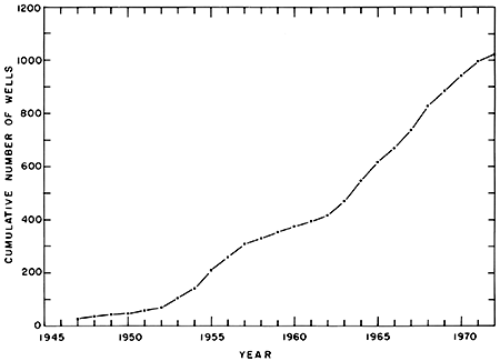
The number of irrigation wells in Greeley and Wichita counties (fig. 6) increased from 28 in 1947 to 1,023 in 1972 according to records of the Division of Water Resources, Kansas State Board of Agriculture. The rate at which wells were installed increased sharply in the early 1950's and again in the early 1960's primarily in response to periods of dry weather. The number of wells has continued to increase, partly to guard against future dry periods, partly to assure maximum crop production, and partly because of increased production of irrigated milo and corn. In areas where water levels and well yields have declined, supplementary wells are being drilled to maintain the same irrigated acreage.
Figure 6--Cumulative number of irrigation wells, 1947-72.
Three attempts have been made to obtain water for industrial or irrigation use from wells drilled into the sandstone aquifer in the counties. A well was drilled at Horace in 1901 for the Missouri Pacific Railway Company, but the well was not used, probably because the yield was inadequate or the water was unsuitable for use in steam boilers. A test well drilled in west-central Greeley County in 1948 reportedly yielded water that contained high concentrations of sodium, and the water never was used. A third well drilled in southwestern Wichita County in 1965 produced sand with the water and the well is not used. Although the sandstone aquifer remains a potential source of water to wells in Greeley and Wichita counties, the aquifer has not been developed at present (1974) for any water supplies.
The 1940 Federal Census shows that 256 acres (100 hm2) were being irrigated in Greeley and Wichita counties in 1939. Data from the U.S. Soil Conservation Service indicate that about 33,000 acres (13,000 hm2) in Greeley County and about 130,000 acres (53,000 hm2) in Wichita County were irrigated in 1972. The annual increase in irrigated acreage follows the same general trend as the rate of well installation (fig. 6).
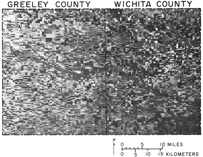
As part of a study to improve accuracy and timeliness of information on land use, such as irrigated acreage, the Kansas Geological Survey is utilizing imagery acquired from the Earth Resources Technology Satellite (ERTS; presently referred to as LANDSAT). Figure 7 is a portrayal of Greeley and Wichita counties produced from imagery at an altitude of 570 nautical miles (1,054 km). The dark-gray areas, primarily in the northern half of both counties, are irrigated fields. Except for a few irrigated fields, most dark-gray areas in the southern half of the counties are fields that have been tilled recently. Light- to medium-gray areas generally are pasture land and fallow or stubble fields.
Figure 7--MSS Band 5 (red band) imagery of Greeley and Wichita counties from an altitude of 570 nautical miles (1,054 kilometers). Imagery by NASA, Earth Resources Technology Satellite, September 23, 1972.
Annual withdrawals of ground water from wells in the unconsolidated aquifer far exceed annual recharge; therefore, ground water is being "mined" in parts of Greeley and Wichita counties. The effects of the mining are a decline in water levels and a decrease in the amount of ground water in storage.
Since 1948, water levels in wells in the parts of Greeley and Wichita counties where irrigation is practiced generally have declined from 10 to about 50 feet (3 to 15 m), as shown on plate 3. The greatest decline, about 55 feet (17 m), is in T. 18 S., R. 37 W. near Leoti. Declines greater than 40 feet (12 m), which generally coincide with areas where wells are concentrated, have occurred in several places in northern Wichita County. Site A (center sec. 4, T. 17 S., R. 40 W.) and Site B (center sec. 13, T. 17 S., R. 37 W.) both are within areas where the pattern on plate 3 indicates that water levels declined from 10 to 20 feet (3 to 6 m) in the period 1948-72.
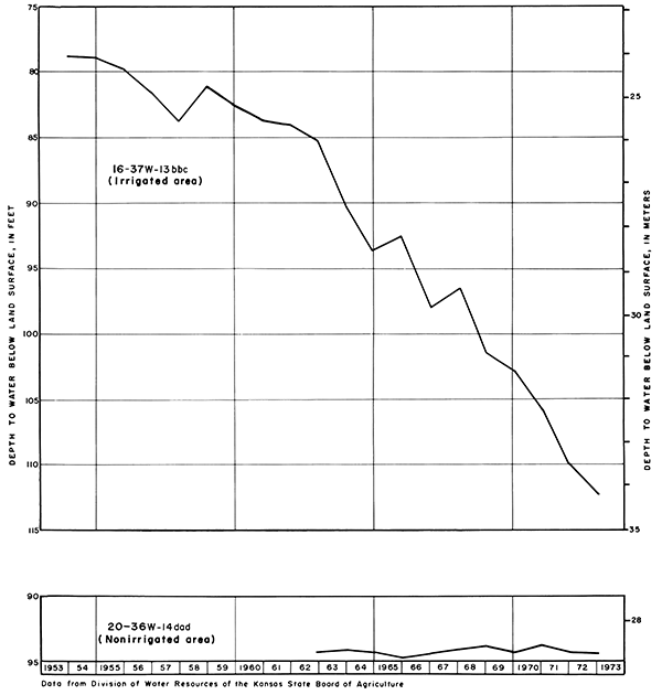
Hydrographs of two wells constructed from data provided by the Division of Water Resources, Kansas State Board of Agriculture, are shown on figure 8. Well 16-37W-13bbc is located in north-central Wichita County where irrigation is practiced extensively. The water-level decline of about 35 feet (11 m) since the early 1950's is typical of irrigated areas. Well 20-36W-14dad is located in southeastern Wichita County where there is little irrigation and where there has been essentially no change in water level.
Figure 8--Hydrographs of water levels in irrigated and nonirrigated areas in Wichita County.
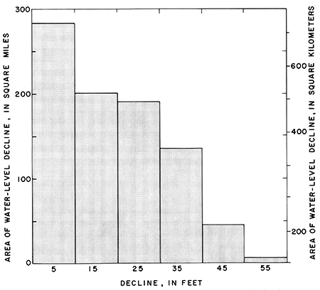
The total size of areas affected by various amounts of water-level declines are shown graphically in figure 9. For example, a decline of 15 feet (5 m) has occurred in an area of about 200 square miles (520 km2).
Figure 9--Total size of area affected by various amounts of water-level decline in the unconsolidated aquifer, 1948-72.
Water-level changes reflect changes in the rate at which water is being recharged to or discharged from the ground-water reservoir. The volume of water released from storage in response to a given water-level decline depends on conditions in the aquifer where the decline occurs. If water in the aquifer is unconfined, as in most of Greeley and Wichita counties, water-level declines represent actual dewatering of part of the aquifer. Specific-yield values under these conditions generally range from 0.05 to 0.30 (Ferris and others, 1962). If water in the aquifer is confined between relatively impermeable geologic units, waterlevel declines in wells represent a reduction in head. The aquifer remains saturated under these conditions so long as the potentiometric head is above the top of the aquifer. The storage coefficient of an aquifer in which water is confined generally is less than 0.001 (Ferris and others, 1962), which is much less than the specific yield of an aquifer in which water is unconfined. Similarly, a much smaller volume of water is released in response to each unit of water-level decline under confined conditions than under unconfined conditions.
The amount of water removed from storage in the unconsolidated aquifer in Greeley and Wichita counties can be estimated by determining the volume of aquifer dewatered (pl. 3) and multiplying by the average specific yield of the aquifer. Assuming an average specific yield of 15 percent, ground-water storage in the counties was reduced about 1.6 million acre-feet (2,000 hm3) in the period 1948-72. The average annual decrease in storage in the period was about 70,000 acre-feet (86 hm3). However, annual reductions in storage are increasing as annual withdrawals increase. Using inflow-outflow values discussed earlier in this report, the decrease of ground water in storage in 1972 was about 158,000 acre-feet (195 hm3) in Greeley and Wichita counties. This decrease in storage amounts to 72 percent of the 220,000 acre-feet (271 hm3) of average annual withdrawals by wells.
The significance of water-level changes with respect to changes in storage also can be interpreted by comparing the percent decline in saturated thickness of the unconsolidated aquifer (pl. 3) to water-level declines in feet. For example, a water-level decline of about 20 feet (6 m) at about one-half mile southeast of Site A amounts to a 50-percent decline in saturated thickness. However, about the same amount of waterlevel decline at Site B amounts to less than a 20-percent decline in saturated thickness. In areas where saturated thickness has declined 40 percent or more, any further increase in the rate of withdrawals may significantly shorten the economic life of the aquifer.
The 1973 price increases for grain and the absence of acreage controls probably will encourage additional development of ground water for irrigation. However, future development may be restrained by the limited availability and increased cost of fuel and electricity. The potential for obtaining irrigation wells (pl. 3) with yields of 500 to 1,200 gpm (32 to 76 L/s) is good in most of northern Wichita County and in extreme northern Greeley County. Increased withdrawals of ground water, however, will increase the rate of water-level decline and the reduction in ground-water storage.
Based on estimates given earlier in this report that:
one can calculate that ground water in Greeley and Wichita counties would be depleted in about 22 years. However, such calculations are erroneous because (1) they are based on estimated values, and (2) they do not account for future changes in water management, irrigation technology, type of crop, or economic factors. When considered with the amount of decline in saturated thickness shown on plate 1, however, one is led to the conclusion that "dry-land" farming probably will be practiced once again in large parts of the area in the not-too-distant future. The entire aquifer never will be completely dewatered and irrigation operations that are favorably located in areas of greatest saturated thickness would be able to continue indefinitely. Serious consideration should be given to restricting additional development of ground water in areas where the saturated thickness already has been reduced by about 40 percent or more.
Numerous plans could be devised to prolong the irrigation economy of the area by making the supply of water last longer. All these plans depend primarily on controlling withdrawals from the ground-water reservoir by limiting (1) the amount of water that can be pumped per well; (2) the number of wells, or (3) the irrigated acreage. These plans also would depend on the operation of a regulatory group with the authority to enforce controls and to encourage conservation of the resource.
The Kansas Ground-Water Management District Number 1 has the legal authority that would allow for managing the ground-water resource intelligently. Application of the legal tools for management, however, should be compatible with the hydrologic laws of nature if they are to be successfully implemented for maximum long-term benefits.
American Society of Civil Engineers, 1972, Ground water management: Am. Soc. Civ. Eng. manuals and reports on engineering practice, No. 40 (updated), 216 p.
Bradley, Edward, and Johnson, C. R., 1957, Ground-water resources of Ladder Creek area in Kansas: Kansas Geol. Survey, Bull. 126, 194 p. [available online]
Ferris, J. G., Knowles, D. B., Brown, R. H., and Stallman, R. W., 1962, Theory of aquifer tests: U.S. Geol. Survey, Water-Supply Paper 1536-E, 174 p. [available online]
French, J. J., 1972, Ground-water outflow from Chino Basin, upper Santa Anna Valley, southern California: U.S. Geol. Survey, Water-Supply Paper 1999-G, 28 p. [available online]
Frye, J. C., 1942, Geology and ground-water resources of Meade County, Kansas: Kansas Geol. Survey, Bull. 45, 152 p. [available online]
Frye, J. C., Leonard, A. B., and Swineford, Ada, 1956, Stratigraphy of the Ogallala Formation (Neogene) of northern Kansas: Kansas Geol. Survey, Bull. 118, 92 p. [available online]
Gillespie, J. B., and Slagle, S. E., 1972, Natural and artificial ground-water recharge, Wet Walnut Creek, central Kansas: Kansas Water Resources Board Bull. 17, 94 p.
Gutentag, E. D., Lobmeyer, D. H., and McGovern, H. E., 1972, Ground water in Kearny County, southwestern Kansas: U.S. Geol. Survey, Hydrol. Inv. Atlas HA-416. [available online]
Gutentag, E. D., and Stullken, L. E., 1976, Ground-Water resources of Lane and Scott Counties, western Kansas: Kansas Geol. Survey, Irrigation Series No. 1, 37 p. [available online]
Hamilton, V. L., 1965, Soil survey of Wichita County, Kansas: U.S. Dept. Agriculture Series, 1962, no. 7, 61 p.
Hantush, M. S., 1964, Hydraulics of wells: Advances in Hydro-Science, v. 1, New York Academic Press, p. 281-432.
Hem, J. D., 1959, Study and interpretation of the chemical characteristics of natural water: U.S. Geol. Survey, Water-Supply Paper 1473, 269 p. [available online]
Hodson, W. G., 1963, Geology and ground-water resources of Wallace County, Kansas: Kansas Geol. Survey, Bull. 161, 108 p. [available online]
Kansas State Board of Agriculture, 1972, Farm Facts, 1970-71; in, Kansas Agriculture: 54th Ann. Rept., Topeka, Kansas, p. 1F-105F.
Kansas State Board of Agriculture, 1973, Farm Facts, 1971-72; in, Kansas Agriculture: 55th Ann. Rept., Topeka, Kansas, p. 1F-105F.
Kansas State Board of Health, 1973, Water quality criteria for interstate and intrastate waters of Kansas: Kansas State Board of Health Regulations, 28-16-28, 5 p.
Kansas State Corporation Commission, 1973, Total natural gas production, by pools, in Kansas for 1972: State Corporation Comm., Conserv. Div., Wichita, Kansas, mimeo. rept., p. 1-13.
Keene, K. M., and Pabst, M. E., 1971, Hydrogeologic data from Gove, Logan, and Wallace Counties, Kansas: Kansas Geological Survey, Basic Data Series, Ground-water Release 2, 76 p.
Keys, W. S., and MacCary, L. M., 1971, Application of borehole geophysics to water resources investigations: U.S. Geol. Survey, Techniques Water-Resources Inv., book 2, chap. E-1, 126 p. [available online]
Lee, Wallace, and Merriam, D. F., 1954, Preliminary study of the structure of western Kansas: Kansas Geol. Survey, Oil and Gas Inv. 11, 23 p.
Lobmeyer, D. H., and Sauer, C. G., 1974, 'Water resources of Hamilton County, southwestern Kansas: U.S. Geol. Survey, Hydrol. Inv. Atlas HA-516. [available online]
Lohman, S. W. and others, 1972, Definition of selected ground-water terms--revisions and conceptual refinements: U.S. Geol. Survey, Water-Supply Paper 1988, 21 p. [available online]
McBee, C. W., Fleming, E. L., Sallee, K. H., and Hamilton, V. L., 1961, Soil survey of Greeley County, Kansas: U.S. Dept. Agriculture, Series 1958, no. 12, 30 p.
McClain, T. J., Jenkins, E. D., Keene, K. M., and Pabst, M. E., 1975, Water resources of Gove, Logan, and Wallace Counties: U.S. Geol. Survey, Hydrol. Inv. Atlas HA-521.
McLaughlin, T. G., 1943, Geology and ground-water resources of Hamilton and Kearny Counties: Kansas Geol. Survey, Bull. 49, 220 p. [available online]
Merriam, D. F., 1963, The geologic history of Kansas: Kansas Geol. Survey, Bull. 162, 317 p. [available online]
Meyer, W. R., Grover, B. L., and Carlson, C. W., 1953, 1952 irrigation experiments: U.S. Dept. Agriculture Soil Conserv. Service Research, 132 p.
Meyer, W. R., Gutentag, E. D., and Lobmeyer, D. H., 1970, Geohydrology of Finney County, southwestern Kansas: U.S. Geol. Survey, Water-Supply Paper 1891, 117 p. [available online]
Pearl, R. H., Roberts, R. S., Keene, K. M., and McClain, T. J., 1972, Water resources of northwestern Kansas: U.S. Geol. Survey, Hydrol. Inv. Atlas HA-429. [available online]
Prescott, G. C., Jr., Branch, J. R., and Wilson, W. W., 1954, Geology and ground-water resources of Wichita and Greeley Counties, Kansas: Kansas Geol. Survey, Bull. 108, 134 p. [available online]
Stallman, R. W., 1965, Effects of water-table conditions on water-level changes near pumping wells: Water Resources Research, v. 1, no. 2, p. 295-312.
Stullken, L. E., Weakly, E. C., Gutentag, E. D., and Slagle, S. E., 1974, Hydrologic data from Greeley, Lane, Scott, and Wichita Counties, Kansas: Kansas Geological Survey, Basic Data Series, Ground-water Release 4, 58 p.
Theis, C. V., Burleigh, H. P., and Waite, H. A., 1935, Ground water in the southern High Plains: U.S. Dept. Interior, Memorandum for the press, Oct. 30, p. 1-4.
Todd, D. K., 1964, Groundwater: Handbook of applied hydrology: New York, McGraw-Hill Book Co., p. 13-1 to 13-55.
U. S. Dept. of Commerce, 1971, Climatological data for Kansas--Annual Summary, v. 85, no. 13, p. 213-224.
U. S. Dept. of Commerce, , 1972, Climatological data for Kansas--Annual Summary, v. 86, no. 13, p. 211-222.
U.S. Geological Survey, 1972, 'Water resources data for Kansas, part I. Surface water records, 1971: U.S. Geol. Survey, Lawrence, Kansas, 206 p.
U.S. Geological Survey, 1973, Water resources data for Kansas, part I. Surface water records, 1972: U.S. Geol. Survey, Lawrence, Kansas, 202 p.
U.S. Salinity Laboratory Staff, 1954, Diagnosis and improvement of saline and alkali soils: U.S. Dept. of Agriculture Handb. 60, 160 p.
Waite, H. A., 1940, Ground water in Scott district, Scott and Finney Counties, Kansas; in, Ground-water resources of Kansas: Kansas Geol. Survey, Bull. 27, p. 73-74.
Waite, H. A., 1947, Geology and ground-water resources of Scott County, Kansas: Kansas Geol. Survey, Bull. 66, 216 p. [available online]
Appreciation is expressed to the residents of Greeley and Wichita counties who gave information regarding their wells and permitted the use of their land and wells for test drilling, discharge measurements, aquifer tests, and water-level measurements. Records and information were obtained through the courtesy of the following drilling companies: Weishaar Drilling Company and Northwest Drilling Company, both of Scott City, Kansas, and Wichita County Development Company, Inc. (formerly Harkness Drilling Company) of Leoti, Kansas.
Appreciation is also extended to Mr. Jack Greer of the Wichita County Assessors office for information on well yields, Mr. Wayne Brenn of the U.S. Soil Conservation Service, Tribune, Kansas, for information on wells and land usage, and the Greeley County and Wichita County road departments for permission to test drill on the rights-of-way.
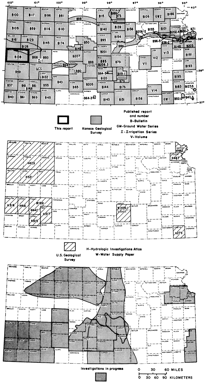
This report was prepared as part of a continuing cooperative program of ground-water investigations by the Kansas Geological Survey and the U.S. Geological Survey. The area discussed in this report and other areas for which ground-water reports have been published or are in preparation are shown on figure 10.
Figure 10--Index maps showing area discussed in this report, and other areas for which ground-water reports have been published or are in preparation.
For those readers who are familiar with or are interested in the metric system, the English units of measurement given in this report also are given in equivalent metric units (in parentheses) using the following abbreviations and conversion factors:
| English unit | Multiply by | Metric unit |
|---|---|---|
| Length | ||
| inch (in) | 2.54 | centimeter (cm) |
| foot (ft) | .3048 | meter (m) |
| mile (mi) | 1.609 | kilometer (km) |
| nautical mile (nm) | 1.85 | kilometer (km) |
| Area | ||
| acre | .4047 | square hectometer (hm2) |
| square mile (mi2) | 2.590 | square kilometer (km2) |
| Volume | ||
| gallon (gal) | 3.785 | liter (L) |
| cubic foot (ft2) | .02832 | cubic meter (m2) |
| acre-foot (acre-ft) | 1.233 X 10⁻³ | cubic hectometer (hm3) |
| Flow | ||
| gallons per minute (gpm) | .06309 | liters per second (L/s) |
| cubic feet per second (f3/s) | .02832 | cubic meters per second (m3/s) |
| Hydraulic conductivity | ||
| feet per day (ft/day) | .3048 | meters per day (m/day) |
| Transmissivity | ||
| square feet per day (f2/day) | .0929 | square meters per day (m2/day) |
| Specific capacity | ||
| gallons per minute per foot (gpm/ft) | .207 | liters per second per meter (L/s)/m |
Most of the definitions of hydrologic terms given below are taken from Lohman and others (1972).
Aquifer--An aquifer is a formation, group of formations, or part of a formation that contains sufficient saturated permeable material to yield significant quantities of water to wells and springs,
Aquifer test--An aquifer test consists of measuring the effect with time of a discharging well on the water level in the well and in nearby wells. Data from aquifer tests are used primarily to determine the hydraulic conductivity, transmissivity, and storage coefficient or specific yield of an aquifer.
Cone of depression--A cone-shaped depression in the potentiometric surface that develops around a well from which water is being withdrawn.
Confined ground water--Confined ground water is under pressure significantly greater than atmospheric, and its upper limit is the bottom of a bed of distinctly lower hydraulic conductivity than that of the material in which the confined water occurs.
Drawdown--The lowering of the potentiometric surface as a result of pumping.
Effective saturated thickness--The effective saturated thickness is that part of the total saturated thickness of an aquifer that yields most of the water to the well, generally composed of medium- to coarse-grained material.
Head--Head, when used alone, is understood to mean static head, which is the height above a standard datum of the surface of a column of water (or other liquid) that can be supported by the static pressure at a given point.
Homogeneous--A material is homogeneous if its hydrologic properties are identical everywhere.
Hydraulic conductivity--If a porous medium is isotropic and the fluid is homogeneous, the hydraulic conductivity of the medium is the volume of water at the existing kinematic viscosity that will move in unit time under a unit hydraulic gradient through a unit area measured at right angles to the direction of flow.
Hydraulic gradient--The hydraulic gradient is the change in static head per unit of distance in a given direction.
Isotropic--A material is considered to be isotropic if all its significant properties are independent of direction.
Potentiometric surface--A surface that represents the static head. As related to an aquifer, it is defined by the levels to which water will rise in tightly cased wells.
Saturated thickness--The saturated thickness of an aquifer is the amount (thickness) of aquifer material that is saturated.
Specific capacity--The specific capacity of a well is the rate of discharge of water from the well divided by the drawdown of water level within the well.
Specific yield--The specific yield of a rock or soil is the ratio of (1) the volume of water which the rock or soil, after being saturated, will yield by gravity to (2) the volume of the rock or soil.
Storage coefficient--The storage coefficient is the volume of water an aquifer releases from or takes into storage per unit surface area of the aquifer per unit change in head. In an unconfined water body the storage coefficient is virtually equal to the specific yield.
Transmissivity--Transmissivity is the rate at which water of the prevailing kinematic viscosity is transmitted through a unit width of the aquifer under a unit hydraulic gradient.
Unconfined ground water--Unconfined ground water is water in an aquifer that has a water table.
Water table--The water table is that surface in a ground-water body at which the water pressure is atmospheric.
Kansas Geological Survey
Placed on web June 25, 2013; originally published in 1976.
Comments to webadmin@kgs.ku.edu
The URL for this page is http://www.kgs.ku.edu/Publications/Bulletins/IRR2/index.html