Kansas Geological Survey, Circular 5, originally issued in 1933
Originally issued in 1933 as Kansas Geological Survey Circular 5. This is, in general, the original text as published. The information has not been updated. An Acrobat PDF version (3 MB) is also available.
The most important natural resources of Kansas are soil, water and climate for upon these depend the products of agriculture which are the chief source of the state's wealth. Water, especially underground water, is a resource, the development of which calls for application of geologic studies because the quantity and other conditions of occurrence of water beneath the earth's surface depend essentially on the distribution of porosity and similar geologic considerations. Accordingly, the State Geological Survey is able to make contribution to development of agriculture by investigating the conditions of ground water supply in Kansas. Such investigations are especially important in parts of the state where surface rainfall is insufficient to permit full utilization of the soil and where there is possible source of water for agricultural uses to be obtained from wells. The following preliminary report presents the results of a study of water supply that may be developed in Scott and Finney counties, Kansas, and possibly in adjacent territory. It is hoped that the information obtained will be useful in enriching the farming industry in this part of Kansas. The Survey will extend its studies of ground water conditions in the state as rapidly as very limited resources permit.
Raymond C. Moore, State Geologist
The Shallow Water Basin lies in central-southern Scott County and the adjacent part of Finney County. The basin derives its name from the fact that water is obtained at depths ranging from 20 to 75 feet and that there is no surface drainage from the area. Whitewoman creek, with a drainage area of approximately 1,175 square miles, terminates three miles south of Scott City. Flood waters from this stream occasionally form a shallow lake at the terminus.
The land surface of this area is, for the most part, flat and smooth. The region is made up of a series of shallow, undrained basins which decline in elevation from Scott City to Garden City.
The writer spent four weeks in the area beginning in the latter part of July, 1933. The data collected are not entirely conclusive since the period of observation was limited. Elevations were run on the irrigation wells and a number of water wells and the depth to water in the wells was measured. This gave information sufficient to contour the water table, in detail in the Shallow Water Basin and in a reconnaissance manner in the rest of the area.
The divides separating the Whitewoman from other drainage areas were followed and sketched on county maps as closely as it was possible to determine them in the flat uplands without accurate levelling.
Measurements of the discharge of some of the irrigation wells were made in order to get a rough estimate of the water being extracted f~om the ground. These measurements were made with a two-foot Cipolletti weir in ditches flowing away from the wells. Information on the number of hours the wells had been pumped this season was furnished by some of the owners.
The writer wishes to acknowledge the kindly assistance rendered by the following residents of the Shallow Water Basin: J. W. Lough, W. D. Luke, Frank Roark, George Weishaar, G. H. Cheney, and many others. For information on Finney County the writer wishes to thank Geo. W. Finnup and Dennis Doty of Garden City. H. Gerald Bobst, with the Division of Water Resources, Garden City, kindly furnished the writer with a series of observations on the level of the ground water table at an abandoned well in sec. 9, T. 20 S., R. 33 W.
The water-bearing sands and gravels of the Shallow Water Basin belong to the Ogallala formation of Tertiary age. This formation rests on an impervious floor or Cretaceous shales. Above the Ogallala formation is the Sanborn formation, which consists chiefly of loess (Elias, 1931, pp. 163-181). The nearest complete exposures of these formations to the Shallow Water Basin are in the bluffs along Ladder (Beaver) creek at the Scott County State Park.
The Ogallala formation of this area covers the High Plains from Ness County, Kansas, to central Cheyenne County, Colorado. The west and south boundaries in eastern Colorado and southwestern Kansas are marked by exposures of Cretaceous. The Ogallala of western Kansas and eastern Colorado is entirely separated from the Ogallala to the west by a strip of Cretaceous shale exposed in the drainage basin of South Platte river and Big Sandy creek in Kiowa and Cheyenne counties, Colorado. Thus, it is evident that no water is furnished to the Ogallala of this part of the High plains by drainage from the Rocky Mountain front.
The north boundary of the Ogallala for this segment of the High Plains is delimited by the Cretaceous outcrops in Smoky Hill river drainage in the tier of counties extending eastward from Wallace County, Kansas.
The Ogallala is made up of lenticular sand and gravel, silt and clay beds. Sand and gravel are usually most abundant in the middle and lower parts of the formation. The sand and gravel bodies are frequently elongated in an east-west direction, forming "channels" or "rivers." These elongated gravel bodies are evidently fillings of ancient channels.
In certain zones the more porous beds have been cemented with calcium carbonate to form "mortar beds."
The permeability of the coarser beds of the Ogallala varies greatly depending upon the size of the sand grains or gravel pebbles, the degree of sorting and the amount of cementing material. The well-sorted coarse sand or gravel allows water to flow through it most freely and will yield water rapidly to a large irrigation well. Any of the silty sands will yield water rapidly enough for an ordinary windmill well.
Since the permeability varies so greatly it is necessary to make preliminary tests with a small rotary drill to locate bodies of coarse material in which to place irrigation wells.
The shale floor upon which the Ogallala formation rests is irregular. In the Shallow Water Basin the depth to shale varies from about 90 to 150 feet. In southwestern Wichita County the shale floor is only 50 feet below the surface in some places. An exposure of Niobrara shale has been noted in T. 19 S., R. 36 W. along Whitewoman creek.
In the southeastern part of Scott County there is another area in which the Cretaceous is near the surface and water is not found in the Ogallala (Adams, 1897). The sheet water apparently flows around the buried Cretaceous hills.
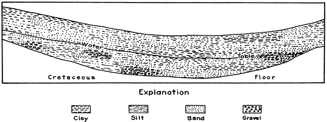
Figure 1 shows a generalized section of the Ogallala formation, the Cretaceous shale floor and the water table.
Figure 1--Diagrammatic east-west section across southern Scott County.
The surface of the underground water is known as the ground water table. This is generally roughly parallel to the surface of the ground, rising slightly beneath the high places and lowering into the valleys if the latter intersect the water table. The irregularities of the ground water table are caused by several factors: namely, the source, or sources, of the water, the direction of underground flow, the permeability of the water-bearing rock or aquifer, and the draining of the aquifer where valleys cut into it below the ground water table.
The rate of flow of underground water is slow and varies with the permeability of the aquifer. Underground water will flow much more rapidly through a coarse sand or pebble gravel than it will through fine sand or sand intermixed with clay or silt. The rate of underground flow in the Shallow Water Basin has not been determined but it must vary greatly from place to place. Local variations in the elevation of the ground water table may thus be caused by varying permeability of the aquifer when there is a general movement of the water.
In western Kansas, between Arkansas and Smoky Hill rivers, the water table in the Ogallala forms a low broad eastward plunging arch. In the adjacent part of Colorado the water table rises slightly and then probably declines westward toward Big Sandy creek, since the elevation of the water table on this creek is only 16 feet higher than it is at Towner, Colorado, near the state line. There is probably a divide in the water table that is approximately coincident with the surface divide between Whitewoman and Big Sandy creeks.
Figure 2--Map of drainage area of Shallow Water Basin.
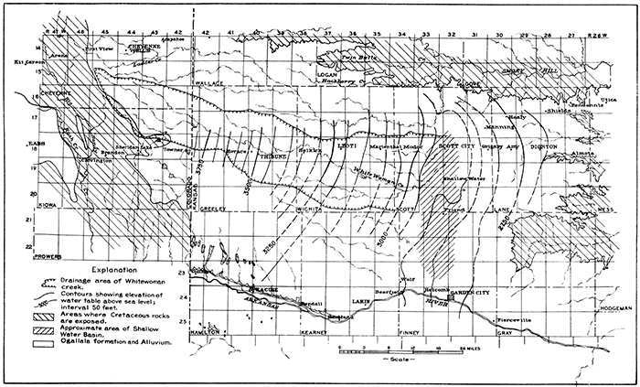
The eastern and northern boundaries of the Ogallala mark these respective margins of the sheet water. The water table is practically coincident with the Cretaceous floor along the border of the Ogallala. The contours on figure 2 show the general slope of the water table or the hydraulic gradient, in this area. Following are some figures on the amount of slope:
| Average eastward slope in feet per mile | ||
|---|---|---|
| Water table |
Ground Surface |
|
| Towner to Leoti | 17 | 16 |
| Leoti to Scott City | 12 | 13 |
| Scott City to Dighton | 9 | 9 |
The average southward slope of the water table from Scott City to Garden City is 2.4 feet per mile and the average surface slope is 3.5 feet per mile. There is likewise an average northward slope from Scott City to the Scott County State Park, but, as shown on figure 3 these figures do not mean that underground water drains away from Scott City to the north, east and south.
Figure 3 shows the irrigation wells in the vicinity of Scott City. The elevations of the water table have been contoured to show the general configuration of this surface. The contours show that the ground water table slopes rapidly into the Shallow Water Basin from the west and gently from the north and east. The local configuration of the water table indicates that water is contributed to the basin chiefly from the west and that there may be a small inward flow from the north and east. The subsurface water divide to the north probably coincides with the surface divide between the Ladder (Beaver) creek and Whitewoman creek drainages. The ground water surface rises slightly to the east but soon reverses and continues the regional eastward slope. The chief avenue of escape of ground water in the Shallow Water Basin is southward to the Arkansas river underflow.
Figure 3--Map of Shallow Water Basin.
From the configuration of the regional water table and the extent of the Ogallala formation it is evident that no surface or subsurface water from the Rocky Mountains can enter the Ogallala formation of Greeley, Wichita, Scott, and Lane counties. Therefore, the sheet water of this large area must have its source in the local rainfall. Probably the major part of the water entering the Shallow Water Basin comes from the drainage area of Whitewoman creek. This drainage area is outlined on figure 2.
Water falling on the surface of the earth may be divided, according to its destinations, into the following parts: run-off (the water carried away by surface streams), evaporation, absorption by plants, and the run-in or ground absorption.
The percentage distribution of precipitation into its various divisions varies a great deal according to local conditions. There is no run-off in the area of the Shallow Water Basin, but the runoff of the Whitewoman creek drainage is contributed to the basin. This creek has a well-defined valley and channel from Cheyenne county, Colorado, to central Scott County, Kansas. At the latter point the valley sides flatten out and the channel diminishes in size until it completely disappears three miles south of Scott City. In times of exceptionally heavy precipitation Whitewoman creek carries a large volume of water that empties into Shallow Water Basin forming a rather large, temporary lake. Such floods usually occur several years apart. Usually all of the run-off sinks into the sandy channel of the creek before reaching the creek's terminus.
Evaporation is high in the High Plains region, averaging over 50 inches per year in most places. The plant absorption is an unknown quantity but is probably relatively low.
The average annual rainfall over the area of Whitewoman creek drainage ranges from 15 to 20 inches. The part of this that enters the ground is not known. Slichter (1906, p. 5) estimates that 60 per cent of an ordinary rain on the sandy bottom land of Arkansas river joins the underflow. Gould (1906, p. 55) thinks that not more than 6 inches of water annually joins the water table of the High Plains. Other students of the subject have estimated smaller amounts.
The drainage area of Whitewoman creek, which is thought to be the chief contributing area to Shallow Water Basin, is 1,175 square miles. For every inch of precipitation added to the water table this area will catch 62,663 acre feet of water. If three inches of water is the annual increment, this would be equal to one square mile covered to a depth of 293 feet, or 187,989 acre feet.
Water probably enters the ground only at places where the Sanborn formation (loess) is absent. This formation is too impervious to permit water to pass through it except in sandy zones and through fissures where the loess is thin. The valley of Whitewoman creek is cut through the Sanborn formation and in places through all of the Ogallala. It is probably in this valley that most of the water enters the water table.
As has been noted already, the amount of water entering the water table is unknown. With the available information the only way the amount of water can be ascertained is by comparing the amount of water being extracted with the changes in the level of the ground water table.
Three wells belonging to Frank Roark pumped a total of 1,702 acre feet of water this season up to August 10.
The developed potential yield of the area is approximately 103 acre feet per day for 25 existing wells that may be used. During the present season only about two-thirds of the wells were in use, and of these only a few were run continuously for more than two or three weeks at one time.
The general level of the water table of the basin fluctuates from time to time. The Division of Water Resources of the Kansas State Board of Agriculture has installed a continuously recording gage in an abandoned well in the NW. cor. of sec. 9, T. 20 S., R. 33 W. The following gage heights were measured with a tape by H. Gerald Bobst at the time of his visits to the station:
| Date | Gage heights |
|---|---|
| 12-28-1931 | 13.80 |
| 2-14-1932 | 13.95 |
| 4-1-1932 | 14.02 |
| 5-9-1932 | 14.07 |
| 6-23-1932 | 13.90 |
| 8-4-1932 | 13.60 |
| 10-12-1932 | 13.42 |
| 11-25-1932 | 13.44 |
| 1-9-1933 | 13.S6 |
| 2-23-1933 | 13.73 |
| 3-30-1933 | 13.80 |
| 5-20-1933 | 13.62 |
The maximum variation in these readings is 0.65 feet. This well is situated at a point that is nearly a mile from the nearest active irrigation well so is away from the influence ot any active pumping and thus probably records the average variation in the water table.
Several check readings were made on recently constructed wells to determine whether pumping lowers the local water table. Some of the wells, after pumping had been suspended several days, showed the water table to be from two to six feet lower than when pumps were installed. However, this is only a local phenomenon as shown by the above table. Other wells have the same water table level, within one foot, as they did when constructed.
Only one partial measurement on the cone of depression was made. A well at the W. 1/4 cor. sec. 29, T. 19 S., R. 33 W., on the Mark ranch, showed a drawdown in the well of 19 feet when pumping 1,070 gallons per minute, and a depression of the water table of two feet at a distance of 30 feet from the well.
The cases where the water has temporarily been lowered as much as six feet are probably caused by low permeability in the surrounding area. Thus, the cone of depression extends far out from the well and regains the general level only slowly.
The water supply has never failed in any of the wells that were properly located. Some of the wells have been pumped continuously for as much as three or four months with only short shut-downs for repairs. The abandoned wells shown on figure 3 in the vicinity of Shallow Water were put down without any preliminary testing and did not penetrate a sufficient thickness of permeable strata for irrigation purposes.
There are several factors that contribute toward making a large water supply in the Shallow Water Basin. They are as follows: (1) The Cretaceous floor of the area is relatively low and forms a partly closed subsurface basin. (2) The Ogallala formation is relatively thick and contains beds of high permeability in which irrigation wells can be installed and get plenty of water. (3) The ground water supply is large and receives not only the ordinary ground water percolation but also the surface drainage from an area of 1,175 square miles comprising the Whitewoman creek drainage area. Thus the Shallow Water Basin is situated in such a position that it gets the greatest benefit from the annual precipitation over a rather large area. Furthermore, there is little likelihood of large quantities of basinward moving underground water being removed from the surrounding territory. The depth to water is much greater to the west and east which makes pumping for irrigation purposes too expensive to be profitable. In places the Cretaceous shales project above the water table. In the valleys, where the depth to water is not so great, the land surface is rolling and not adapted to irrigation over any large areas.
The amount of "lift", or height that the water must be raised, varies from about 25 to 100 feet. The "draw-down", or lowering of the water table while pumping, varies greatly but probably averages less than 20 feet.
The most satisfactory pumping plant for the Shallow Water district has been found to be a turbine pump in a single well. The usual procedure in constructing the wells is to sink a 42-inch hole which is cased with temporary casing. The well and casing are usually set on shale or hard clay. Perforated casing, or casing made by laying up concrete or cast iron rings, is placed inside the large, temporary casing and the space between these two casings is filled with gravel. The large temporary casing is then removed.
The pump used is the deep-well turbine multiple stage centrifugal type. This, with its pipe, is placed inside the perforated casing with the pump bowls well below the water level. The pumps are operated with vertical electric motors mounted on the pump shaft, or with gasoline or Diesel motors connected to the pump shaft with belts. The pumping plants of this type are described in "Irrigation Pumping Plants", Report of Kansas State Board of Agriculture, Division of Water Resources, vol. 50, no. 198, Topeka, 1931.
Future development of irrigation in the Shallow Water Basin will be governed by the following factors: (1) The total amount ot water available, (2) the practicability of pumping the water, and (3) possible laws governing subsurface water-rights.
The total amount of water available is not known, but judging from the present configuration of the water table and the amount of water being extracted there is an adequate quantity of water to supply additional development. However, future development must be carefully guided so that over-development can be avoided. In order to have a check on the results of more development, the state should install several additional gaging stations in the Shallow Water Basin. Ground water table level gaging stations should also be placed in the drainage area to the west in order to study the flow of water into the basin.
The practicability of pumping water in this area is determined by the results. The soil is very fertile and will yield excellent crops, but there is a rather large investment involved in installing a pumping plant and the power cost for lifting the water is a considerable factor.
At the Garden City experiment station well the cost for electric power in 1929 was $6.87 per acre foot of water pumped with a lift of 112-114 feet. The pump delivered 800 gallons per minute. A well near the center of sec. 10, T. 20 S., R. 33 W., delivers 1,466 gallons per minute at a power cost of $2.33 per acre foot. Another well, in the SE. 1/4 sec. 15, T. 19 S., R. 33 W., produces 1,284 gallons per minute at a power cost of $3,38 per acre foot. The amount of lift could not be measured on the latter two wells.
Laws governing the water rights and extraction of ground water should be instituted to prevent over-development and protect the individuals that have developed pumping irrigation in the area.
Adams, G. I., 1897, Report of Board of Irrigation Survey and Experiment, for 1895 and 1896, pp. 111-115, Topeka.
Elias, M. K., 1931, The geology of Wallace County, Kansas: Kansas Geol. Survey, Bul. 18, 254 p. [available online]
Gould, C. N., 1906, Geology and water resources of the eastern portion of the panhandle of Texas: U. S. Geol. Survey, Water Supply Paper 154, 64 p. [available online]
Slichter, C. S., 1906, The underflow in Arkansas valley in western Kansas: U. S. Geol. Survey, Water Supply Paper 155, 90 p. [available online]
Kansas Geological Survey, Shallow Water Basin in Scott and Finney Counties, Kansas
Placed on web Feb. 3, 2016; originally issued in Oct. 1, 1933.
Comments to webadmin@kgs.ku.edu
The URL for this page is http://www.kgs.ku.edu/Publications/Bulletins/Circ5/index.html