Kansas Geological Survey, Bulletin 233, p. 449-461
by
Cliff Frohlich1 and R. K. Matthews2
1The University of Texas Institute for Geophysics
2Brown University
STRATA-VARIOUS version 1.3 is a computer program written in Fortran 77 to perform two-dimensional forward modeling of stratigraphic processes. We designed specific features of the program to investigate orbital forcing of high-frequency glacioeustasy. This requires forward modeling of many hundreds of sea-level stillstands and the graphic display of relatively precise spatial details. To use this program, the user constructs files that specify the times and elevations of sea-level stillstands, the initial basement topography, numerous parameters that control the geometry and physical properties of stratigraphic beds, the isostatic response of the lithosphere, the pattern of tectonic subsidence and uplift, the number and scale of desired output cross sections, etc. Two features of this program are especially novel. Whereas many forward-modeling programs store information about stratigraphic beds in fixed-size horizontal bins, our program retains in memory the precise locations of all horizontal locations where any stratigraphic bed undergoes any distinct change. This allows us to obtain regional cross sections and magnified sections that preserve information about the geometry and lithology of individual beds. Second, for clastic sediments we have developed a realistic parametric scheme for describing how sea-level variation affects the sediment discharge rate. The parameters that control this scheme have simple physical interpretations in terms of the dimensions, erosion rates, etc. for the alluvial valley responsible for the sediment supply. In this article we give various examples of STRATA-VARIOUS graphic output to illustrate model sensitivity and to demonstrate some of the options available.
An Acrobat PDF file containing the complete paper is available (880 kB).
As small computers have become increasingly fast and inexpensive, it has become attractive to devise explicit forward-modeling schemes that mimic various stratigraphic processes. At present, there are several research groups developing computer programs for stratigraphic modeling. As illustrated in this volume, the available computer models are diverse, partly because they have been developed to focus on different stratigraphic problems. For example, previously we developed a one-dimensional model to study sequence stratigraphy and diagenesis in carbonates (Matthews and Frohlich, 1987), whereas in this article we discuss a two-dimensional model for clastic sediments.
There is also diversity because computer modeling of stratigraphic processes is a young discipline, and so the field has not yet determined the best choices for certain programming approaches (table 1). For example, a fundamental choice is whether to determine bed geometry by solving differential equations that represent the physical laws of flow and sediment transport (Tetzlaff, 1986), by using geometric rules that approximate relationships distilled from years of field observations [e.g., Kendall et al. (1989)], or by using a combination of these approaches (Lawrence et al., 1990). Another important choice concerns the resolution of information storage: whether the program stores the type, amount, and location of sediment in discrete horizontal bins or whether it stores the location of all significant bed contact points, etc. regardless of scale.
Table 1--Menu of choices for the computer modeler. *Option chosen in STRATA-VARIOUS.
|
Our motivation to construct STRATA-VARIOUS flows primarily from an interest in orbital forcing of high-frequency glacioeustasy (Matthews and Poore, 1980; Prentice and Matthews, 1988). Because the effect of orbital forcing on sea level is nonlinear, certain features of the stratigraphic record occur only every few million years or so (Matthews and Frohlich, 1991). Thus we required a program that could deal with hundreds or thousands of sea-level stillstands. Furthermore, spatial resolution must be precise to display the anticipated geometric complexity accurately. A serious review of existing modeling efforts [e.g., Butcher (1988)] suggested that our concepts and purposes were different enough to require a new model to fit our problem-solving needs.
Our essential purpose here is to describe the STRATA-VARIOUS computer modeling program that we have developed over the past three years. With respect to the choices described in table 1, STRATA-VARIOUS is two-dimensional, it models clastics, and it utilizes geometric rules to determine bed form. It stores information at all relevant critical points instead of only in fixed-width storage bins. It allows the user the option of employing an external subsidence or uplift model that along with isostasy modifies the elevation of the basement. In the following section we describe the program and the model output from a typical model run in some detail. We then illustrate the range of possible model outputs by presenting several model runs with slightly different input parameters.
The development of the STRATA-VARIOUS model is an ongoing project. All the illustrations presented here were constructed using STRATA-VARIOUS version 1.3. Although elsewhere we have presented cross sections and other information produced by a preliminary version of STRATA-VARIOUS (Matthews and Frohlich, 1991), this is the first article to describe the program systematically.
Each model run of the STRATA-VARIOUS program requires input files that specify sea-level history, the initial geometry of the margin where sediments will be deposited, and various other parameters related to sediment supply, depositional geometry, compaction, and tectonic and isostatic subsidence. These parameters control how the rate of sediment input varies with changes in sea level and define the properties of the deposited beds, such as the geometry (fig. 1). These input files also control features of the desired output, such as the time period covered by the model run, interim times when cross-sectional plots are desired, and the scale of various output plots.
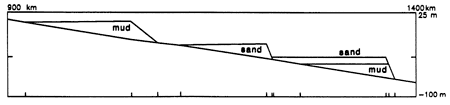
Figure 1--The geometry of topset-foreset beds deposited by subroutine FORESET depends on whether there is only mud, only sand, or both sand and mud available for deposition. The slope of the foreset is less steep when there is only mud available (left) than when there is only sand (center). When both sand and mud are available (right), the program deposits a topset layer of sand overlying a wedge-shaped mud layer. In some situations not all the available sand and mud will be deposited by FORESET, especially if the basement slope is too steep or the relative proportions of sand and mud make it impossible to use all the sediments. STRATA-VARIOUS places sedimentary beds only at sea-level highstands and lowstands rather than building beds incrementally at constant-length discrete time intervals. The small vertical tick marks at the bottom of the figure mark the critical points where the program must calculate the properties of all beds (see text).
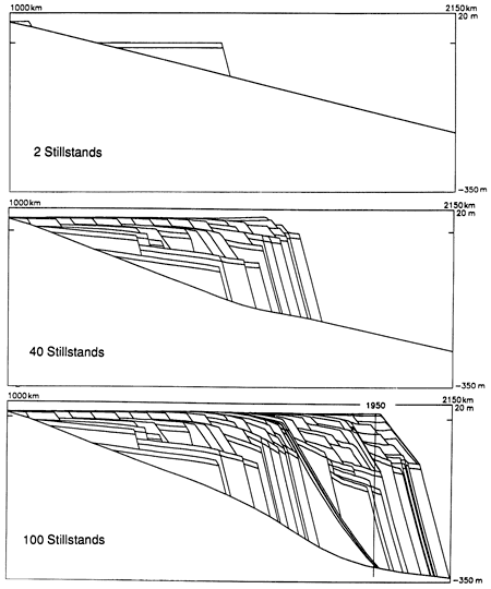
For example, for the run depicted in fig. 2 we begin with a basement surface with a steady slope of 0.2 m/km and then step through 100 sea-level stillstands corresponding to the passage of 1,708,000 years. Subroutine FORESET places beds only at sea-level stillstands. Calculating bed geometry only at stillstands has several advantages. It accounts for the observation that sediments are most likely to be trapped during periods of rising sea levels, and the upper surfaces of stratigraphic beds are generally set during periods when sea levels change slowly. Clearly, a stillstand-controlled algorithm reproduces stratigraphy more faithfully than algorithms that calculate thicknesses at intervals encompassing many stillstands, for example, 200,000 years. However, with respect to information storage and time of computation, a stillstand-controlled algorithm is much more efficient than algorithms that iterate many times between each stillstand interval, for example, every 1,000 years.
Figure 2--Three cross sections showing the sediment geometry at different times during a STRATA-VARIOUS model run. The model run begins at stillstand 60 and runs to stillstand 160. (Top) The geometry after 74,000 years (2 stillstands). (Center) The geometry after 696,000 years (40 stillstands). (Bottom) The geometry after 1,708,000 years (100 stillstands). Note how the basement surface warps downward as a result of isostatic flexure of the lithosphere. For the model run shown, we use a flexural wavelength x, = 100 km and a mantle response time tc = 5,000 years. The sea-level curve is the dynamic model (fig. 9, center), and we employed a variable sediment source model (fig. 3, right). The vertical line at horizontal location 1,950 km shows the position of the well logged in fig. 7.
Subroutine FORESET produces three different types of beds, as described in fig. 1. For each new bed this subroutine determines critical points, for example, the shoreward-most sand-mud contact, the point where the topset-foreset slope changes, and the seaward-most sand-mud contact. These critical points become model-defined horizontal locations for subsequent operations. For new critical points that are sufficiently close to a previously defined critical point, there is a snap-on provision that assigns them the same horizontal location, thus reducing the size of storage arrays for all future program calculations. At present, STRATA-VARIOUS version 1.3 does not emplace bottomset beds (although these were included in a previous version of the program) so that critical point storage is reduced and graphic output is simplified.
After each bed is deposited, at each critical point subroutine COMPACTION compacts all underlying beds according to an exponential rule. In particular, if sediment of uncompacted thickness dhu and initial porosity p0 is overlain by material whose density multiplied by its thickness is Td, then the compacted thickness dhc is given by
dhc = dhu {1 - p0 [I - exp(-Td / C)]}, (1)
where C is a lithology-dependent sponginess parameter that controls how the compaction varies in response to the weight of the overburden. Typically, C is of the order of 1-2 x 10⁶ kg-m.
In addition, subroutine ISOSTASY uses a line load approximation [see Turcotte and Schubert (1982, p. 125)] to model the isostatic response of the basement to the sediment load. This assumes that the basement responds to the weight of the sediment as a thin elastic plate underlain by the viscous asthenosphere. For example, consider two adjacent critical points on a newly deposited bed, and suppose that the product of the overlying sediment density, average thickness, and critical point separation distance is S, which we call the mass intensity. Then, after time t passes, the isostatic deflection w at other critical points situated a distance x away is
w = kS[1 - exp(-t / tc)] exp(-|x| / xc) x[cos(x / xc) + sin(|x| / xc)]. (2)
Here, xc is the flexural wavelength of the lithosphere, which is related to lithospheric thickness and elasticity, and tc is a time constant related to mantle velocity and flow. Typically, xc is a few tens of kilometers and tc is a few thousand years. k is a normalization parameter that depends on the mechanical properties of the lithospheric plate [see Turcotte and Schubert (1982)]. We determine the overall isostatic adjustment of the basement by superimposing similar deflections for the mass deposited between all adjacent critical points. Furthermore, because of the time dependence, the mass intensity S may not be entirely compensated at a subsequent stillstand occurring at time T. We account for this by including a term for the uncompensated mass intensity S exp(-T/tc) and a term for the intensity produced by any new mass deposited during the interval T.
Because the load geometry produced by sea-level changes is not localized like the load geometry of sedimentary beds, we account for isostatic effects in a separate subroutine, ISOSTASYH2O. After a change in sea level dy, this subroutine ensures that the resulting asymptotic equilibrium basement deflection in the seaward direction is dyρH2O/ρmantle, where ρH2O and ρmantle are the density of seawater and the mantle, respectively. Inland the asymptotic deflection is 0, and near the shoreline the two asymptotes are joined by a curve of wavelength xc.
To investigate how sea-level history affects stratigraphic beds, it is important to model the effect of sea-level changes on sediment input rates. Our conceptual model is that the sediment source is a river, such as the Mississippi, that flows from some distant source through an alluvial valley of approximate horizontal dimensions D and W. At its mouth the river delivers sand and/or mud to be deposited in beds, as in figs. 1 and 2. The river carries sand and mud produced at rates Vsand and Vmud by the distant source. As time passes, both erosion and deposition occur in the alluvial valley. The grade of the stream is tied to sea level by a user-defined rule. Below grade level sediment fills the flooded valley. Above grade level there is horizontal migration of a cutbank at rate Rh and vertical erosion down to grade at rate Rv over the entire subaerial alluvial valley. This additional eroded material, together with Vsand and Vmud, is available for deposition. However, note that, when sea level is high, the grade level rises and, until deposition fills the watershed up to grade level, only a fraction fsand/mud of the eroded and distant sediment reaches the river mouth.
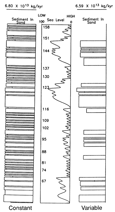
We do the analysis and bookkeeping for this scheme in subroutine SOURCESINK. This subroutine allows a realistically broad variety of possible responses to sea-level variation. In addition to the sea-level input file, there are nine parameters that fix subroutine performance. These are the minimum and maximum grade levels hmin and hmax allowable for the alluvial valley, and the seven variables from the preceding paragraph: D, W, Vsand, Vmud, Rh, Rv, and fsand/mud. If the rates Vsand and Vmud are high and the watershed dimensions D and W are small, the sediment discharge rate at the river mouth is nearly constant (fig. 3, left-hand side). In the opposite case there is significant sediment discharge at the river mouth only during periods of relatively low sea level (fig. 3, right-hand side), because at all other times all the available sediments are deposited to fill the flooded alluvial valley to grade. This demonstrates that sediment discharge depends on whether the sea-level curve is approximately sinusoidal or consists of distinct epochs of relatively high and relatively low sea levels (see fig. 3).
Figure 3--By varying the nine parameters in subroutine SOURCESINK that control how river discharge depends on sea-level history, one obtains different responses to changes in sea level. For example, if the source model incorporates an abundant distant sand source (Vsand = 6.5 x 10¹³ kg/yr) and a small watershed (D = 100 km, W = 50 km), there is an approximately constant discharge of sand (bar graph on left) regardless of sea level (center graph). Alternatively, if Vsand = 1.0 x 10¹³ kg/yr and if there is a large continental valley (D = 1000 km, W = 500 km) that traps all the sediments except at times of low sea levels, we obtain a highly variable discharge of sand (bar graph on right). In this case, which corresponds to the model used to generate fig. 2, sand is generally available only at times of low sea level. In these bar graphs the horizontal axis for the bars is sediment discharge rate and the vertical axis is time. Thus the area of each bar is proportional to the total volume of sand produced between successive stillstands. The numbers in the center graph designate selected stillstand numbers.
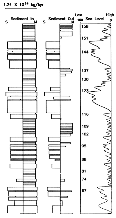
After each run of the program, we can generate various tables or plots that summarize processes or specific strata of interest. We employ only four Calcomp plotting calls to generate all cross sections and graphic output, so the program does not depend on any particular graphics hardware or software package. For this reason and because we wrote the program in Fortran 77, the model can be run at almost any institution on a variety of computing systems. As an example of graphic output, fig. 4 depicts the horizontal extent and time of deposition for sand beds. Figure 5 plots the sediment input produced by SOURCESINK and the sediment output that is left undeposited by FORESET.
Figure 4--Time-space plot showing the time of deposition (vertical axis) and horizontal extent (horizontal axis) for sand beds deposited in the model run of fig. 2. The horizontal scale is the same as that in fig. 2, and time runs from oldest at the bottom (stillstand 60) to most recent at the top (stillstand 160), an interval of 1,708,000 years. The numbers in the time-space rectangles designate the stillstand number at the time of deposition of the plotted sand bed.
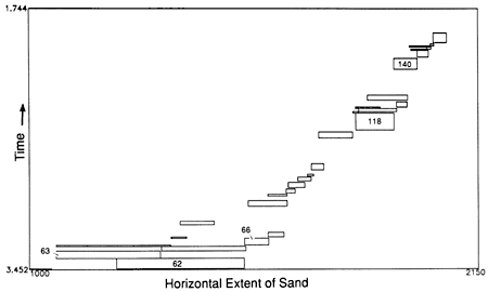
Figure 5--Sediment budget summary plot for the model run of fig. 2. The left-hand bar graph shows the discharge of sand (S) and mud (M) produced by SOURCESINK and available for deposition by FORESET. The right-hand bar graph shows how much of this is not deposited in the cross section by FORESET (see fig. 1) and thus is left over to be deposited elsewhere. We assume that this sand is deposited in deep water out of cross section. On the right is the sea-level curve, as in fig. 3.
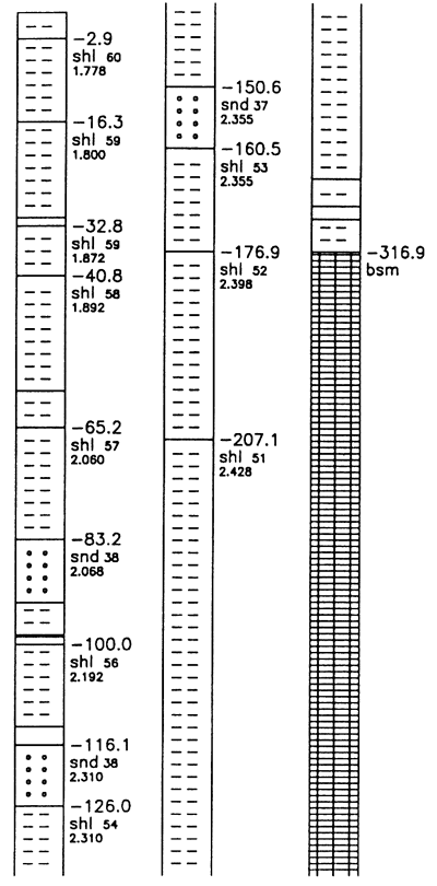
Because the program stores the location of all bed contacts, pinchouts, etc., it is possible to obtain cross sections at any desired scale without loss of precision (fig. 6). Thus, for applications that require information about stratigraphic beds over a broad range of dimensions (from meters to hundreds of kilometers), the data storage methodology employed by STRATA-VARIOUS is superior to that in programs which store information about strata in discrete equal-width bins. In addition, by using subroutine DRILLWELL, the modeler can obtain a log of the properties of all the sedimentary beds beneath any particular horizontal location (fig. 7).
Figure 6--Expanded scale version of a portion of the bottom panel of fig. 2, illustrating the detail preserved during the model calculation. The numbers on each bed designate the stillstand when the bed was deposited.
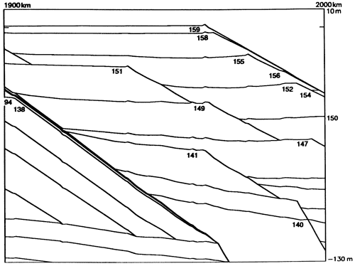
Figure 7--Well-log cartoon produced by subroutine DRILLWELL for the run depicted in the bottom panel of fig. 2. The numbers at the upper right of the thicker beds designate the elevation (in meters) of the top of the bed, the porosity (percent), and the time of deposition (M.Y. B.P.) of sand (snd) and shale (shl) beds. To avoid confusion in labeling in this plot, very thin beds are unlabeled.
The power of forward models lies in the fact that the geologist-modeler can perform thought experiments. These thought experiments may be highly quantitative and of sufficient complexity to defy the possibility of performing them in one's head. Thus it is possible to determine which features of stratigraphic beds are affected by either gross or subtle changes in each of the physical processes that affect deposition. In this section we present some additional examples to illustrate the range of behavior possible with version 1.3 of STRATA-VARIOUS. For each example all the input files and parameters are identical with those used to generate figs. 2, 3 (right), and 5-7, except when indicated otherwise.
Perhaps the most important influence on stratigraphic character is sea-level history. If sea level follows a simple cosine variation (fig. 8, top), the resulting cross sections consist of two sequences of beds, deposited during periods of high and low sea level, respectively. Both sequences prograde seaward because, as the basement responds isostatically to the sediment load, additional space becomes available for sedimentary fill in the nearshore regions. However, in this model run fsand/mud = 0, and thus sand can reach the river mouth only at times of low sea level (fig. 9). For this reason, only the lower sequence possesses sand topset beds.
Figure 8--Effect of sea-level history on cross sections. (Top) Sea level is a simple cosine curve (fig. 9) with a period of 40,000 years and an amplitude of 50 m. The sea-level curves are the dynamic (center) and statistical (bottom) models described in the text and by Matthews and Frohlich (1991).
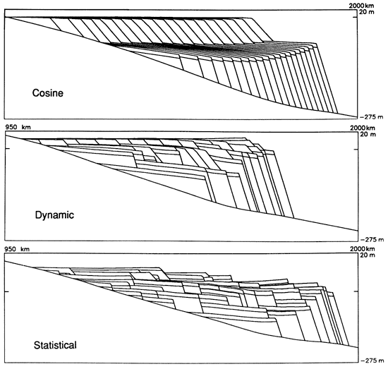
Figure 9--Discharge of sand produced by SOURCESINK for the three sea-level models used in fig. 8: a cosine model with a period of 40,000 years and a peak-to-peak amplitude of 50 m and the dynamic and statistical models described in the text and by Matthews and Frohlich (1991).
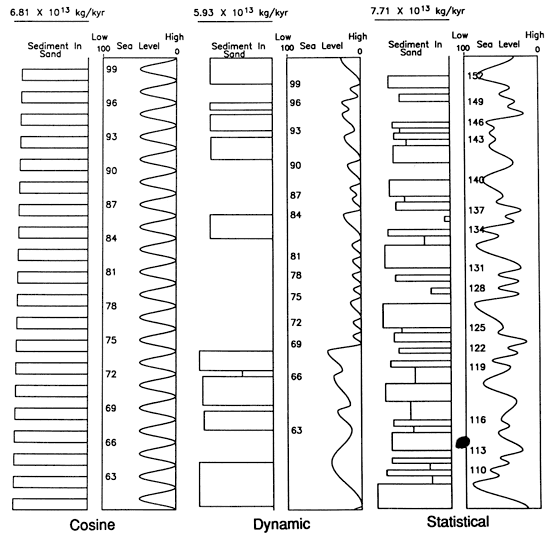
Because of reasons reviewed by Matthews and Frohlich (1991), the character of sea-level variations is different in the Tertiary and in the Pleistocene. The dynamic model corresponds to the situation in the Tertiary. In this model sea levels are usually relatively high and sea-level fluctuations are relatively small, except for large excursions to very low sea levels at approximately 2-m.y. periods. The dynamic model produces regular prograding sequences of shale beds overlying and interspersed with larger, more varied beds possessing sand topsets, produced at times of low sea level [figs. 2 and 8 (center)]. The statistical model corresponds to the situation in the Pleistocene. For this model (fig. 8, bottom) there is a broader range of stillstand durations and of peak-to-peak amplitudes. Because there are no extended periods of very low or very high sea levels, sand topset beds occur throughout the cross section.
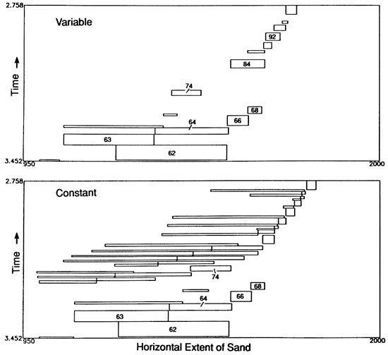
As described previously, the source model that determines available sediments at the river mouth has profound effects on stratigraphy. Depending on the parameterization of the source model, one obtains a variety of cross sections from the same sea-level curve. For example, for the dynamic sea-level curve we can obtain either an approximately variable or constant discharge model (fig. 3). For the variable discharge model the sand beds generally lie at the seaward edge of the shelf and are usually deposited only during occasional periods of exceptionally low sea levels. However, in the example shown in figs. 8 and 9 sand beds do occur at relatively high sea levels (between stillstands 82 and 95) after an extensive period (stillstands 69-82) in which the alluvial valley was filled with sediments. Conceptually, subroutine SOURCESINK has a memory that keeps track of the interactions among erosion, deposition, and sea-level history within the alluvial valley.
In the constant discharge model sand beds extend a considerable distance landward of the shelf throughout much of sea-level history (fig. 10) because they are deposited regularly during both highstands and lowstands. In this example the memory of the alluvial valley is small and deposition is overwhelmed by sediment discharged from the distant mountain source. It is also possible to adjust SOURCESINK to vary the average sediment discharge and the proportions of sand and mud.
Figure 10--Effect of sedimentary source model variations on time-space plots (see fig. 4). (Top) Variable rate source model (fig. 3) run for 40 stillstands, producing the cross section in the center panels of figs. 2 and 8. (Bottom) A 40-stillstand run of the constant rate source model (cross section not shown). Note that the sand beds generally extend over a much broader portion of the shelf for the constant rate model than for the variable rate model.
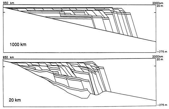
In general, the effect of varying isostatic parameters is more predictable and more subtle than the effects caused by different sea-level curves or sedimentary source models. If the lithosphere is stiff and the flexural wavelength is long, stratigraphic beds tend to spread out horizontally over the shelf region (fig. 11). In contrast, if the flexural wavelength is small, the lithosphere tends to subside locally and the entire stratigraphic sequence is confined to a smaller region. Moreover, the basement surface tends to have more relief because the weight of sediment depresses the basement beneath and because for small wavelengths there are more pronounced secondary uplifts around the load point [see Turcotte and Schubert (1982)].
Figure 11--Effect of isostasy on cross sections. For these cross sections the flexural wavelength x, is 1000 km (top) and 20 km (bottom). Compare these sections to figs. 2 and 8, where x, is 100 km.
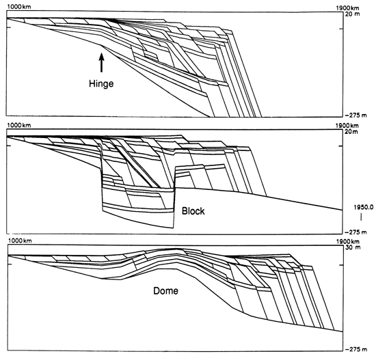
In certain modeling situations there exist regions that undergo uplift or subsidence during specific epochs. We provide for this in subroutine TECTSUB. For example, we can make the entire basement surface undergo steady uplift or subsidence, or we can subside the surface away from a particular hinge point (fig. 12). Furthermore, we can mimic the action of block faults, uplifting domes, or more complex patterns during the model run by specifying that parts of the basement move up or down at fixed rates between particular stillstands. The justification for the rules driving routine TECTSUB may be either ad hoc or derived from an understanding of the tectonophysics controlling crustal and mantle processes.
Figure 12--Examples of tectonic motions available by calling subroutine TECTSUB, which imposes epochs of subsidence or uplift on portions of the basement surface. (Top) There is steady subsidence about a hinge point at horizontal location 1,250 km. (Center) There is an epoch of steady subsidence for 380,000 years (20 stillstands) of a block of material between 1,250 km and 1,450 km followed by an interval of 316,000 years (20 stillstands) with no additional subsidence. (Bottom) Uplift of the basement produces a dome that alters the sediment geometry.
There is no single computer model or modeling approach that is satisfactory for all applications. Here, we emphasize the strengths of STRATA-VARIOUs and, in passing, point out how the choice of a modeling program can influence data acquisition strategy. Two features Of STRATA-VARIous are quite different from other available modeling schemes. These are the way we store information about stratigraphic beds and the source model we employ to determine sediment discharge.
During computation, we store information about stratigraphic beds at all critical points on the basement surface, that is, at all locations where physical properties of beds change (see fig. 1). These critical points include horizontal locations where the basement changes slope, where an overlying stratigraphic bed terminates, or where the bed undergoes any distinct change. At each time step the program calculates or stores the physical properties (thickness, porosity, overburden, etc.) of all the beds for all the critical points beneath the bed. At horizontal locations between critical points, subroutines such as DRILLWELL (fig. 7) simply interpolate between critical points to determine bed properties. Unlike STRATA-VARIOUS, most other two-dimensional modeling programs store information about beds only for a grid of equally spaced horizontal locations or bins.
There are advantages and disadvantages to our critical point method as opposed to the fixed-bin method. An advantage of the critical point method is that we can recover information about bed geometry or physical properties on any scale. This is desirable because there is a high density of critical points in horizontal locations where there are numerous pinchouts, bed thickness changes, etc.; thus no information is lost by lumping data into larger than desirable bins. Similarly, there is a low density of critical points where the stratigraphy is simple or where beds are nonexistent. Thus the critical point method is especially useful for performing thought experiments that require analysis over a large range of spatial scales. It is possible to display stratigraphic cross sections without the graininess inherent in the fixed-bin models.
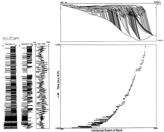
One disadvantage of the critical point method is that it complicates the program architecture necessary to store information about individual beds. We circumvent this by employing a real-valued array, Hcrit, which records the horizontal locations of the critical points, and a real-valued array Bed, which records the overburden and initial thickness at critical points within all the stratigraphic beds. An integer array Ibed contains pointers to the first and last location in Hcrit and Bed for the information about each bed. For long model runs a disadvantage of the critical point method is that, as the number of stillstands increases, the computation time increases nonlinearly. This is because both the number of beds and the number of critical points are roughly proportional to the number of stillstands. Nevertheless, we routinely process model runs of >300 stillstands (fig. 13) in a matter of hours on Sun workstations.
Figure 13--Graphic output for a longer model run extending over 337 stillstands over an interval of 5 m.y. and corresponding cross section (see fig. 4 for explanation). On the same time scale are plots of the sea-level curve and the sediment budget summary (see fig. 5 for explanation). For this model run we used the statistical sea-level curve, but all other model parameters are the same as those used in fig. 2.
A second important and novel feature of STRATA-VARIOUS is the sedimentary source model embodied in SOURCESINK. This model is physically appealing because it requires only a few parameters. Moreover, each of these parameters has a straightforward physical interpretation, such as alluvial valley dimension or erosion rate. Thus it is possible to deduce plausible physical estimates for model parameters for different river systems.
Note that this strategy is contrary to the experience of most sedimentologists and stratigraphers. Most are accustomed to gathering abundant data and then writing regression equations that express the existence of structure within the data. Unfortunately, the mathematics of structure within data does not necessarily reveal the physics of process. Nor does it reveal the importance of this particular process to the overall problem. Model building forces us to think about the physics of process, to choose one or more parameters that point in the right direction, and to test the sensitivity of the overall system to these parameters. Where sensitivity testing shows that a process or a parameter strongly influences overall model outcome, additional field data can be gathered in a format consistent with the construct of the model. Because each of the parameters controlling our sedimentary source model has a straightforward physical interpretation, as a first modeling step we can choose the parameters without having access to empirical information from a river system of interest and without making statistical fits to empirical information.
In this article we have presented results generated by STRATA-VARIOUS version 1.3; however, we expect to continue program development in response to future research interests. For example, one relatively straightforward modification is to add a greater variety of bed forms. These will include bottomset beds in addition to the wedge-shaped topset-foreset beds now available. We also could construct beds with geometries allowing us to model carbonate reef formation or turbidite deep-sea regimes.
At present, STRATA-VARIOUS version 1.3 does not include the erosion of previously deposited sediments. Erosion may be crucial for modeling various stratigraphic regimes; however, it also complicates computation in several ways. For example, at any stillstand erosion may remove beds that can then be removed from storage arrays, but it also adds critical points because the erosional surface cuts across previously deposited beds. Furthermore, erosion complicates the calculation of porosity changes resulting from compaction. At a particular time step the degree of compaction no longer depends solely on the weight of the overburden, because sediments "remember" whether they were compacted at previous times by overburden beds that have since been eroded away.
One of the initial objectives of our modeling effort was to investigate stratigraphic complexity resulting from a combination of short-period and long-period cycles. This requires that our models cover a thousand or more stillstands over periods of 20 m.y. or so. Although this is possible to do on a large computer with the present program, it is not yet convenient on computers such as our Sun workstations. One way to reduce storage and computing times on long model runs would be to define packages of beds with a single horizon defining the base of each package and another horizon defining the top. Each package would undergo compaction and subsidence as a unit, with properties depending on averages or combinations of properties of the beds within the package. This would be especially useful for groups of beds that had become fully compacted. Packaging would allow us to remove critical points in locations where they are closely spaced or where all lie on a surface of nearly constant slope. This would also increase efficiency because we would not need to calculate or store the properties of individual beds.
We consider STRATA-VARIOUS version 1.3 an operational problem-solving stratigraphic tool. We have designed this tool primarily to investigate the implications of orbital forcing of glacioeustasy. Our personal applications center around Cenozoic passive margins, but applications are straightforward to any time interval suspected of having a significant volume of ice on the continents. We see forward models as the logical extension of the thought experiments employed so fruitfully by physicists in the first half of the twentieth century as they struggled to develop the concepts of relativistic and quantum physics. Just as stratigraphers as observers learned long ago that they needed a field notebook to keep track of their observations, stratigraphers as thinkers will learn that they require computer-based forward models to keep track of their thoughts and their precise consequences.
Butcher, S. W., 1988, The MARGIN program-the fundamental design of a method for studying basin dynamics: M.Sc. thesis, Brown University, Providence, Rhode Island, 59 p.
Imbrie, J., 1985, A theoretical framework for the Pleistocene ice ages: Journal of the Geological Society, v. 142, p. 417-432
Kendall, C. G. St. C., Strobel, J., Harris, P. M., Moore, P., Cannon, R., Bezdek, J., and Biswas, G., 1989, Simulation of Capitan shelf margin (Late Permian, Guadalupian) of West Texas/New Mexico--a response to eustatic change and an example of the use Of SEDPACK (abs.): 28th International Geological Congress, Abstracts, v. 2, p. 174
Lawrence, D. T., Doyle, M., and Aigner, T., 1990, Stratigraphic simulation of sedimentary basins--concepts and calibrations: American Association of Petroleum Geologists, Bulletin, v. 74, p. 273-295
Matthews, R. K., and Frohlich, C., 1987, Forward modeling of bank-margin carbonate diagenesis: Geology, v. 15, p. 673-676
Matthews, R. K., and Frohlich, C., 1991, Orbital forcing of low frequency glacioeustasy: Journal of Geophysical Research, v. 96, p. 6,797-6,803
Matthews, R. K., and Poore, R. Z., 1980, Tertiary δ18O record and glacio-eustatic sea-level fluctuations: Geology, v. 8, p. 501-504
Prentice, M. L., and Matthews, R. K., 1988, Cenozoic ice-volume history--development of a composite oxygen isotope record: Geology, v. 16, p. 963-966
Tetzlaff, D. M., 1986, Computer simulation model of clastic sedimentary processes (abs.): American Association of Petroleum Geologists, Bulletin, v. 70, p. 655
Turcotte, D. L., and Schubert, G., 1982, Geodynamics--applications of continuum physics to geological problems: Wiley, New York, 450 p.
Kansas Geological Survey
Comments to webadmin@kgs.ku.edu
Web version April 23, 2010. Original publication date 1991.
URL=http://www.kgs.ku.edu/Publications/Bulletins/233/Frohlich/index.html