Kansas Geological Survey, Bulletin 194, pt. 1, originally published in 1969
U.S. Geological Survey, Lawrence, Kansas
Originally published in 1969 as part of "Short Papers on Research in 1968," Kansas Geological Survey Bulletin 194, part 1, p. 3-7. This is, in general, the original text as published. The information has not been updated.
The Kansas District of the Water Resources Division, U.S. Geological Survey, in cooperation with the State Geological Survey of Kansas, has been establishing a data-processing system, including storage and retrieval, for hydrologic data since 1963. The data bank developed contains thousands of well-inventory, water-quality, water-level, and lithologic-log records. Accuracy of data in the bank is assured through a system that begins with coded forms, includes computer programs that check for logic errors, and ends with manual proofing of computer output. Numerous computer programs that manipulate and analyze data from the bank have been written, and these programs have enhanced the interpretive capability of a hydrologist. Methods of examining data that were not practicable before the advent of the computer are now feasible. Use of the computer has encouraged development of new analytical techniques and the adaptation of methods from other scientific fields for the interpretation of hydrologic data. Utilizing a high-speed digital computer, the Kansas District can do specific tasks, achieving higher interpretive quality in less time and at a lower cost than was possible previously.
The Kansas District of the Water Resources Division, U.S. Geological Survey, in cooperation with the State Geological Survey of Kansas, has been developing techniques for handling hydrologic data by means of high-speed digital computers since 1963, in accord with guidelines established by the Water Resources Division, Washington, D.C. (Johnson, 1965; Lang and Irwin, 1965). The techniques of coding, storing, retrieving, and analyzing data are designed to facilitate the manipulation and synthesis of large quantities of basic data from a data bank. These data consist of tens of thousands of data sets (Table 1), a set being, for example, one chemical analysis of water or one well-inventory record. Many programs have been written for use with these data; some programs were developed for the IBM 7040 and GE 625 computers at the Computation Center, The University of Kansas, and are also available for use on the USGS's IBM 360-65 computer in Washington, D.C.
Handling water data manually is a time-consuming, impractical job when large-scale problems are considered, and large-scale problems are becoming more evident as population and industry increase. Many data-handling procedures used in the past, both for reports and in answering requests for information, require a multitude of repetitious operations. The availability of the digital computer makes possible the development of an automatic data-processing system as an obvious solution for increasing the efficiency of handling water data. The computer can do repetitive work efficiently, allowing the hydrologist to pursue solutions to problems for which time formerly was not available.
The development of a successful automatic data-processing system involves two major steps: (1) a method must be perfected for entering the basic records into a computer data bank; and (2) programs must be developed to instruct the computer to select specific data from the bank and rearrange or manipulate the data to obtain the desired print-out.
Table 1--Hydrologic data for Kansas (available, coded on forms, and in computer bank).
| Data category | Cards per data set |
Estimated total available sets |
Coded | Data bank | |
|---|---|---|---|---|---|
| Water quality | 2 | 20,000* | 15,000 | 15,000 | |
| Water level | 5 to 500 | 5,000 | 1,200 | 1,100 | |
| Well inventory | 2 | 60,000 | 8,000 | 8,000 | |
| Lithologic log | |||||
| Detailed | 3 to 20 | 15,000** | 500 | 500 | |
| Abbreviated | 1 to 3 | 7,000*** | 7,000 | ||
| * Includes 7,000 from ground-water sources, 5,000 from surface-water sources, and 3,000 from petroleum industry sources. ** Includes 10,000 from USGS-KGS cooperative program and 5,000 from drillers. *** Includes logs noted in column 3 plus logs from petroleum industry sources. |
|||||
The use of a computer allows the hydrologist to examine all available data, thereby reducing costs since chances for error are reduced to a minimum. The actual cost of an average project may not be reduced, but the data are examined more thoroughly in the same length of time. Also, once complete data banks are established and retrieval programs developed, requests for information can be answered reliably in a fraction of the time previously required.
One of the first steps in designing an effective system for using the digital computer in hydrology, or for any field requiring large amounts of basic data, is to prepare forms to facilitate coding and keypunching onto cards. Kansas District personnel have worked primarily with methods for coding of ground-water data. Presently, well-inventory, water-quality, water-level, and lithologic-log data are coded as collected. Much of the historical water-quality and water-level data have been coded and punched, but well-inventory and lithologic-log data are complete only for active projects.
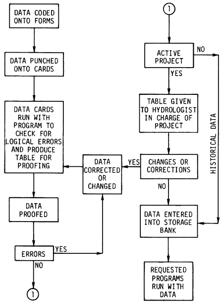
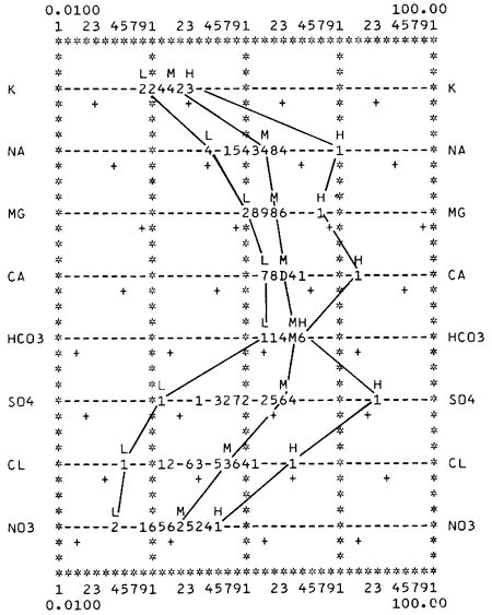
The transferring of data from various source documents to coding forms and then to computer cards and tape is the most critical step in the development of a high-quality storage and retrieval system. Data must be accurate, or the most sophisticated computer program can do nothing meaningful. The Kansas District employs a system of data-checking procedures that includes manual proofreading and computer programs that check for errors in logic (Fig. 1). Manual proofreading is a step that cannot be computerized, except in data-handling methods. However, simple logic checks, such as checking for letters in punch-card fields reserved for numbers or examining for illegal codes, are easily programmed for the computer. This type of program for checking data punched on cards not only provides a check on errors in coding and key punching but also lists the data in an easily proofread form. Thus, the data pass through a series of manual and computerized checks until errors are minimal. If data from an active project are involved, a final check is made by the project chief. Normally, this is the first time he sees the data after having delivered the coded forms to the computer applications section.
Figure 1--Flow chart of data-handling procedure for computer applications, Kansas District.
The major costs in establishing a data storage-and-retrieval system are in the preparation of the basic data; however, if programs are not available for the type of manipulation required, a significant cost may ensue in writing and testing programs. The writing and development of a simple program may take only a small number of hours to program and require but a few minutes on the computer, but complex and sophisticated programs can require many months to program and many hours of computer time to test. In both cases, the initial objectives for writing the program must be satisfied, i.e., the use of the program must be a money- and time-saving tool and the procedure must be worthwhile.
When the data have been punched correctly on cards and placed in a computer data bank, the data can be manipulated in many ways to reveal facets of the hydrology in a more comprehensive form. Much basic data is presented initially in tables for use in data interpretation and in published reports. Programs for producing tables of well-inventory, water-quality (Morgan et al., 1966), water-level, and lithologic-log data are designed to present the data in a form that the hydrologist has been accustomed to using. Data also can be sorted in various ways, such as by aquifer or by well depth, so that the tables may be arranged differently for different purposes. Programs for specialized or abbreviated tables usually are written as the need for them arises.
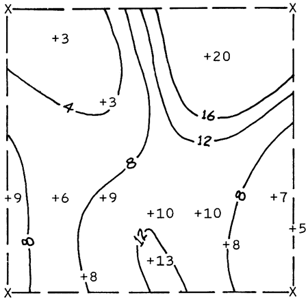
While the various types of tables of basic data are the fundamental methods of presenting data from computer programs, data presented in a diagrammatic format may yield much more information with a minimum of effort by the hydrologist. The several types of diagrammatic output employed include map and graph plots. Maps (Fig. 2), with specific parameters located at their relative positions in two-dimensional space, are commonly used tools in the interpretation and illustration of hydrologic phenomena. The programs available for plotting maps (Good, 1964) are designed to adjust the output to any specified map scale, to sort for a parameter within the data set or calculated from the data, and to sort for data from specified aquifers. The hydrologist can request a series of maps with the desired parameters and be assured that the data are located accurately and are represented completely. Such maps are used principally for interpretive purposes; however, the line printer produces maps that are accurate enough for publication.
Figure 2--Map showing saturated thickness (in feet) of Pleistocene aquifer in T. 16 S., R. 19 W., Rush County, Kansas. (Locations of data points designated by plus sign; corners of township defined by X's. Scale: 1:126720. Solid lines drawn manually.)
Program development for graphic output has been concentrated on presentation of water-quality data because of an emphasis on preparation of all available Kansas water-quality data for computer use and the adaptability of these data to graphic representation. The graphic methods (Angino and Morgan, 1966) first programmed were those most commonly used by hydrologists. Two of these programs present a single water analysis on one graph. The Stiff (Stiff, 1951) (Fig. 3) and the Collins (Collins, 1923) diagrams show selected constituents in milllequivalents per liter.
Figure 3--Stiff diagram of a water analysis from the Pleistocene and Dakota aquifers of Rush County, Kansas. (Scale of diagram is 10 milliequivalents per liter to the left and right of the vertical center zero line. Each dash equals 0.5 meq/L.)
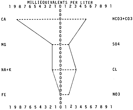
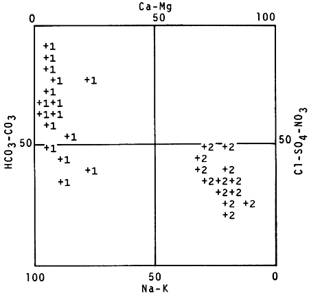
A group of water analyses can be represented on quadrilinear and trilinear diagrams (Piper, 1953) that show the relationship of the ions (Fig. 4). These diagrams aid in classification of water types, as well as in pointing out possible mixing of several water types. By use of another program, water can be categorized according to degrees of salinity hazard, denoting suitability for irrigation. The program uses a technique requiring that water conductivity be plotted against the sodium-adsorption ratio (Agriculture Handbook No. 60, 1954). The computer output for all these diagrams includes supplementary tables that identify the analyses used and the aquifer from which the water was obtained.
Figure 4--Quadrilinear Piper diagram of water quality data sorted by aquifer from Rush County, Kansas. (Pleistocene aquifer designated by numeral 2, Dakota Formation by numeral 1, locations of data points by plus sign. Constituent symbols and grid drawn manually.)
Methods of analysis or manipulation that are less commonly used because of excessive amounts of time involved in manual preparation of the data have been programmed to aid the hydrologist in expanding his interpretive capability. These methods normally involve a great amount of mathematical computation. An example of this type of program is one that calculates a number of additional parameters from basic water-quality data, sorts these data into groups by aquifer, and determines for each aquifer group the maximum, mean, minimum, and sample standard deviation for each parameter. Each chemical constituent is converted to milliequivalents per liter, where possible, and the basic statistics are calculated. Fifty ratios may be calculated for each analysis and the basic statistics determined for the aquifer groups. These ratios are used to determine origin of the water, to indicate mixing or contamination, and to define water types. A group of 100 analyses from 10 aquifers have over 10,000 values determined by the program; in many cases each value involves several computational steps.
A program involving a large amount of computation time is one that calculates drawdown at points within an infinite well field (Fader, 1967). This program uses the permeability, saturated thickness, and storage characteristics of the aquifer, the average pumpage per well, and the number of wells affecting drawdown to produce a table of drawdown values.
Another program was written to manipulate the water-quality data collected periodically at selected stations along a reach of a surface stream. This program will handle up to 50 stations and will calculate 23 parameters for each chemical constituent at each significant station for a given period of time. The results are sorted by station and parameter, placed in order by date, and put in a table format--each station having up to 24 tables. The amount of manual work necessary in the past to handle these data was prohibitive and often the results were inconclusive. Therefore, because time was not available, shortcut methods, such as educated guesses, dictated the resulting interpretation.
Many previously used methods of data manipulation and analysis for which programs are available have been expanded to include new techniques of analysis. This has been made possible by the hydrologist's realization that he now has time available for more thorough interpretation of the voluminous data. Also, new methods of looking at data are being developed and new programs are being written. For example, a program, which is a semilog plot of water-quality data (Fig. 5) designed for both surface- and ground-water data, can sort the data by date of collection, stream discharge or well depth, geologic source of ground water, and constituent value. These sorted data are tabulated along with values for the maximum, mean, minimum, and sample standard deviation. The constituents or parameters are plotted using a log10 scale. This plot emphasizes water groupings and anomalies, as well as the range of concentration of the parameters. Surface-water data also are plotted with respect to time, denoting seasonal changes that affect the water quality. The program as written can sort the data in thousands of possible ways, and the data arrangement and plot scale on the graph can be adjusted to an almost infinite number of combinations. This variety of options allows the user to try many patterns for the most convenient grouping.
Figure 5--Semilog plot of designated chemical constituents in water from the Ogallala Formation in Kearny County, Kansas. (L = low, M = mean, and H = high constituent values in meq/L. Numbers and letters signify analyses at a position on the dashed line. Milligrams per liter scale given by plus symbols. Solid lines drawn manually.)
Examples of other programs are as follows: one for the examination of water mixtures such as may be found in a study of water contamination, a well pumping from two aquifers, or a well inducing infiltration from a stream; another for estimating water-level fluctuations in a well by using the water levels of an adjacent surface stream; and another for estimating yearly recharge and discharge to a water-table aquifer.
Many programs that have been written for various fields of the social and physical sciences also can be applied to hydrologic work. The statistical routines written for medical research by the BIOMED group at the University of California (Los Angeles) (Dixon, 1965) are examples. One routine, the polynomial regression, is being used in evaluating water-quality data.
Samples of time required to run some of the hydrologic programs on the GE 625 computer are shown in Table 2. In all examples, the time used is insignificant with respect to the amount of work accomplished by use of the program.
Table 2--Time for running various water-data programs through the GE-625 computer.
| Programs | Data sets |
Output | Computer time, min. |
||
|---|---|---|---|---|---|
| Tables | Plots | ||||
| Data checking | |||||
| Well inventory and water quality |
176 | 1 | 1.85 | ||
| Water level | 10 | 10 | .20 | ||
| Tabulation | |||||
| Water quality | 114 | 1 | 1.21 | ||
| Water level | 10 | 10 | .31 | ||
| Diagrammatic | |||||
| Map plots | 176 | 1 | 9 | 1.45 | |
| Graph plots | |||||
| Stiff diagram | 114 | 47 | .36 | ||
| Collins diagram | 114 | 41 | .42 | ||
| Piper diagram | 114 | 2 | 7 | .47 | |
| Irrigation classification diagram | 43 | 2 | 2 | .32 | |
| Semilog diagram | 114 | 19 | 18 | 1.44 | |
| Other programs | |||||
| Ratio determination | 114 | 3 | 1.05 | ||
| Recharge calculation | 325 | 1 | .04 | ||
Evolution of computer applications in hydrology in Kansas has included design of coding schemes and forms, formulation of a system for checking data, development of computer programs for writing tables of data and plotting a variety of maps and graphs from these data, and adaptation of statistical program packages to these data. The purpose of the development of these applications has been to provide hydrologists with computer facilities for increasing their efficiency, to reduce costs, and to improve their professional capabilities.
Angino, E. E., and Morgan, C. O., 1966, Application of pattern analysis to the classification of oil-field brines; in, Computer Applications in the Earth Sciences--Colloquium on Classification Procedures, D. F. Merriam, ed.: Kansas Geol. Survey, Computer Contrib. 7, p. 53-56.
Collins, W. E., 1923, Graphic representation of analyses: Ind. and Eng. Chem., v. 15, 394 p.
Dixon, W. J., ed., 1965, BMD, Biomedical computer programs: Univ. California School of Medicine, Los Angeles, 620 p.
Fader, S. W., 1967, Notes on the shape of the truncated cone of depression in the vicinity of an infinite well field: Kansas Geol. Survey, Spec. Dist. Pub. 33, 11 p.
Good, D. I., 1964, Fortran Il trend-surface program for the IBM 1620: Kansas Geol. Survey, Spec. Distrib. Pub. 14, 54 p.
Johnson, A. I., 1965, Computer processing of hydrologic and geologic data: Ground Water, Jour. Tech. Div., Natl. Water Well Assoc., v. 3, no. 3, p. 15-23.
Lang, S. M., and Irwin, J. H., 1965, Punch card system for storage and retrieval of ground-water data: Internatl. Assoc. Sci. Hydrology, Quebec Meeting, Pub. no. 68, p. 800-805.
Morgan, C. O., Dingman, R. J. and McNellis, J. M., 1966, Digital computer methods for water-quality data: Ground Water, Jour. Tech. Div., Natl. Water Well Assoc., v. 4, no. 3, p. 35-42.
Piper, A. M., 1953, A graphic procedure in the geochemical interpretation of water analyses: U.S. Geol. Survey, Ground-Water Note 12, 14 p.
Stiff, H. A., 1951, The interpretation of chemical water analysis by means of patterns: Jour. Petroleum Tech., Tech. Note 84, 15 p.
U. S. Salinity Laboratory Staff, 1954, Diagnosis and improvement of saline and alkali soils: U. S. Dept. Agriculture, Agric. Handbk no. 60, 80 p.
Kansas Geological Survey, Short Papers on Research in 1968
Placed on web July 26, 2011; originally published in Feb. 1969.
Comments to webadmin@kgs.ku.edu
The URL for this page is http://www.kgs.ku.edu/Publications/Bulletins/194_1A/index.html