Kansas Geological Survey, Current Research in Earth Sciences, Bulletin 241, part 3
Prev Page--Introduction || Next Page--GPR Data and Interpretations at Study Sites
![]()
![]()
![]()
Kansas Geological Survey, Current Research in Earth Sciences, Bulletin 241, part 3
Prev Page--Introduction ||
Next Page--GPR Data and Interpretations at Study Sites
![]()
GPR acquisition, processing, and display are very similar to the methods used in seismic reflection. However, GPR has much higher resolution and is sensitive to changes in electromagnetic, rather than acoustic, properties. GPR reflections are caused by electromagnetic waves encountering media that have different electrical properties--namely, boundaries consisting of dielectric-constant contrasts. Reflection strength is approximately proportional to the difference of the dielectric constants at the boundary (Davis and Annan, 1989). Values for dielectric constants range from 1 for air, 4 to 8 for limestone, 5 to 13 for shale, 5 to 40 for clay, and 81 for water (Daniels, 1996; Davis and Annan, 1989; Schon, 1996). Dielectric constant values affect the velocity of electromagnetic waves through a material. One-way velocities for the following materials are 0.3 m (1 ft)/nanosecond (ns) for air, 0.11-0.15 m (0.36-0.49 ft)/ns for limestone, 0.08-0.13 m (0.26-0.43 ft)/ns for shale, 0.05-0.13 m (0.16-0.43 ft)/ns for clay, and 0.03 m (0.09 ft)/ns for water. Antenna frequencies typically range from 10 to 1,000 MHz. Vertical resolution varies from 1 to 1.5 m (3.3-4.9 ft) for low-frequency antennas (10-100 MHz) to 0.02 to 0.3 m (0.06-0.98 ft) for higher-frequency antennas (500-1,000 MHz) for most materials (Davis and Annan, 1989). These reported velocities were used as a basis for elevation corrections and interpretation in this study and were verified by comparison of reflection times with unit thicknesses on the outcrop.
GPR data are typically shown as common offset profiles with trace-amplitude variations representing differences in reflectivity. The vertical scale of a profile shows two-way travel-time, usually in nanoseconds (ns = 1 x 10⁻⁹ s), and the lateral scale is distance (trace spacing x number of traces) along the profile.
Two study sites were chosen, based on the quality of exposure, ease of access, availability of geologic data from previous studies, and relevance of the facies and stratal geometries to reservoirs in Kansas. Site preparation included clearing the antenna path of obstructions, flagging the stations, collecting relative elevation information, and creating photomosaics of the outcrops for comparison with GPR data. The removal of material such as small rocks and grass from the antenna pathway enhanced antenna coupling with the ground and reduced spurious diffractions. It also allowed relatively consistent lateral antenna movement, ensuring even trace spacing. In order to retain the same antenna pathway for each of the profiles collected and to allow for the comparison of GPR data with the outcrop, stations were flagged at 1.5- or 3.1-m (4.9- or 10.2-ft) intervals. The antenna pathways were located approximately 1 m (3.3 ft) behind the outcrop face to minimize the possibility of interference from out-of-plane reflections from the contact between rock and air. The collection of relative elevation information allowed the GPR data to be corrected for elevation differences. These corrections aided interpretation of reflections and correlation with the appropriate horizons on the outcrop. Elevations were obtained using a level and rod and are accurate to within 3 cm (1.2 in). The photomosaics were gathered in increments of either 7.6 or 15.2 m (24.9 or 49.8 ft), depending on the overall size of the outcrop at each site.
The equipment used for the study was a GSSI SIR System-8 GPR unit with a 500-MHz antenna. Record lengths of 20 to 80 ns were collected at a rate of 12.8 scans/second as the antenna was pulled along the pathway. For long profiles, greater than 30 m (98 ft) in length, the equipment was placed within a large-wheeled garden cart to facilitate continuous profiling. A short marker-pulse was recorded at each station, every 1.5 or 3.1 m (4.9 or 10.2 ft), and a double pulse was recorded at every fifth station, every 7.6 or 15.2 m (24.9 or 49.9 ft), in order to allow GPR data to be correlated with the outcrop. The tape unit recorded coherent, cable-induced system noise beginning at approximately 40 ns on each trace. This system noise masked some reflection information below this level, greatly reducing the signal-to-noise ratio of longer scans. System noise is readily identified because it always appears at the same times across the entire GPR record and has relatively consistent amplitude. Reflections differ in that they almost always have some variability in return times and change in amplitudes due to minor changes in velocities and depth to reflectors across an outcrop.
It was not possible to obtain velocity information from common-depth-point (CDP) gathers in this study because a monostatic antenna was used (e.g., the source and receiver were the same antenna). Instead, velocity information was obtained by comparing reflection travel times with interpreted unit thickness measured from outcrop. Use of a bistatic antenna would allow CDP-velocity information to be gathered because the source and receiver antennas could be separated and data could be gathered at a variety of offsets. The GPR data for this study were collected in a continuous manner, which resulted in rapid data collection at the cost of lateral variability between traces and no vertical stacking. Collection of the data in a stepped manner would have allowed for even trace spacing as well as the vertical stacking of traces. Vertical stacking can increase signal-to-noise ratios of data and allow deeper reflectors to be imaged. Even spacings and vertical stacking of traces were not possible due to equipment limitations.
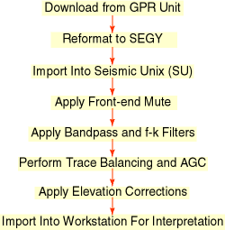
The GPR data were converted from RADAN format into 4-byte SEGY format for digital-signal processing with the program Seismic UNIX (SU). The data were time- and distance-scaled by a factor of 1 x 10⁶ for viewing and processing purposes. Data processing did not vary much between the data from the two sites; a generalized processing flow chart is shown in fig. 1.
Fig. 1--Generalized GPR-data processing flow-chart for this study. Front-end mutes removed the high-amplitude reflection from the air-ground interface, allowing trace balancing to enhance low-amplitude reflection information. Frequency-wave number (f-k) filtering removed most of the system noise recorded below 40 ns. Low-frequency noise was removed or reduced by bandpass filters. Automatic gain controls (AGC) were used to allow low-amplitude events to become more visible and aid interpretation. Static shifts were applied to individual traces to account for elevation differences during data collection.
Prev Page--Introduction || Next Page--GPR Data and Interpretations at Study Sites
Kansas Geological Survey
Web version September 15 1998
http://www.kgs.ku.edu/Current/1998/martinez/martinez3.html
Comments to webadmin@kgs.ku.edu