Kansas Geological Survey, Open-file Report 2000-43
Part of the Upper Arkansas River Corridor Study
KGS Open File Report 2000-43
June 2000
A Report to the Kansas Water Office, Contract No. 00-113
A Kansas Water Plan Project
Problem
Objectives and Scope of Work
Previous Studies
Location and Geohydrologic Setting
Bedrock
Pliocene and Undifferentiated Pleistocene Deposits
Arkansas River Alluvial Valley
Procedures
Discussion
Appreciation is expressed to local, federal and other state agencies and institutions for assistance in conducting the Upper Arkansas River Corridor (UARC) study. The study is being conducted in cooperation with the Kansas Water Office; Division of Water Resources, Kansas Department of Agriculture; Pesticide Program, Kansas Department of Agriculture; Southwest Kansas Groundwater Management District No. 3; Kansas Department of Health and Environment; and Southwest Kansas Local Environmental Planning Group. The UARC study is partially funded by the State Water Plan through the Kansas Water Office.
Other members of the Geohydrology section provided useful input. Melany Miller assisted in the production of the report. Mark Schoneweis provided assistance with graphics. Thanks to Susan Stover and Eric Hargett for thorough reviews and comments that helped to improve the report.
This report presents lithologic characterization of the unconsolidated Tertiary and Quaternary deposits that compose the aquifer system underlying and surrounding the Arkansas River in southwest Kansas, particularly along the Arkansas River corridor west of the Crooked Creek-Fowler fault. It includes a brief review of literature concerning the geology and hydrology of the study area, and describes geologic cross sections developed for the study area.
The cross sections represent the most detailed characterization of the lithology in the Upper Arkansas River corridor to date. The sections typically are in agreement with information from previous publications. However, cross sections in the previous literature lacked lithologic detail and were typically based on data from test holes spaced many miles apart. The geologic sections in this report fill in gaps and add lithologic detail. They help to ascertain the location and continuity of individual lithologic units, both coarse-grained and fine-grained, and thus their potential influence on ground water and contaminant movement.
A procedure was developed to electronically represent, manage, and display lithologic data as cross sections with accompanying color gradation. The cross sections help to characterize the shallow alluvial aquifer, the deeper High Plains aquifer, and a relatively impermeable layer that commonly is present between the two aquifers. The alluvial aquifer comprises a fairly continuous permeable unit of sands and gravels, especially south of the Arkansas River. The thickness of the permeable material varies considerably and exceeds 50 feet in places. North of the Arkansas River the alluvial valley is quite narrow in stretches and the alluvial aquifer typically is thinner and less continuous. The deeper High Plains aquifer varies widely in type of material, thickness, and layer continuity, and has more clay, silt, and cemented units than the alluvial aquifer. The relatively impermeable layer between the aquifers is discontinuous and highly variable in thickness and materials composition. It is generally made up of clay interbedded with lenses of silt, caliche or (cemented) sand. Geologic sections suggest that greater hydraulic connection between the shallow and deep aquifers occurs south of the Arkansas River.
The Arkansas River in southeastern Colorado and westernmost Kansas is one of the most saline rivers in the United States. Consumption of water by evapotranspiration in Colorado has substantially decreased the flow and greatly increased the salinity of the river water entering Kansas. The evapotranspiration includes consumptive losses of water from fields, irrigation canals and ditches, and reservoirs. In addition to salinity, the concentration of many other dissolved constituents in the river water is high.
Ground-water levels have declined in the High Plains aquifer in southwest Kansas from decreased recharge from the river and consumptive pumping from the aquifer. As a result, some or all of the Arkansas River flow entering Kansas from Colorado is lost in the river stretch from the state line to Dodge City. Some of this loss is due to infiltration and consumptive use of water diverted from the river for irrigation and also to phreatophyte transpiration and river evaporation. Saline water from the river and fields irrigated with river water is infiltrating to and contaminating the ground water in both the alluvial and High Plains aquifers in the upper Arkansas River corridor. Ground-water declines in the High Plains aquifer have also decreased the amount of fresh subsurface flow to the alluvium that can dilute salinity and other constituent concentrations. Another ground-water quality problem in the upper Arkansas River corridor is increasing nitrate concentrations in many well waters. The ground waters which have been and could become contaminated by salinity and nitrate include sole sources for several towns and cities, including Syracuse, Lakin, Garden City, Cimarron, and Dodge City.
The distribution of salinity and the mechanisms for entrance to and movement of the saline water within the aquifer system have not been well known. An assessment of the source, migration, and present and possible future extent of the ground water contamination is critical for developing plans for minimizing or mitigating water-quality problems in the aquifers. The Upper Arkansas River Corridor (UARC) Study was developed to provide information that will improve understanding of the river and ground-water salinity in the corridor to enable agencies, municipalities, farmers, and industries in the area to better manage water resources to minimize or mitigate water-quality problems.
Layers of low permeability clays and silty clays typically underlie the Arkansas River alluvium. This low-permeability material restricts the infiltration of the saline river water to the deeper ground water. As a result, perched saline water exists in some areas above the main body of the High Plains aquifer. Clay layers also occur within the main aquifer and further retard the downward movement of saline water. The sand and gravel units comprising the alluvial and High Plains aquifers vary substantially in hydraulic conductivity and thickness. The distribution and character of the low and high permeability layers in the aquifer system (both the alluvial and High Plains aquifers in most of the study area) have not been well known. Understanding of the distribution of the different lithologic units is necessary for conceptual and quantitative models of the intrusion of the saline river water in the areas of the river valley and ditch irrigation, and the migration of the saline water within the High Plains aquifer.
Description of components of the objectives and scope of work for the overall project have been listed by Whittemore et al. (1996). This report addresses objectives related to the intrusion of the saline water into the alluvial and High Plains aquifers and migration of the intruded water. It describes the lithology of unconsolidated sediment deposits in the five-county area (Figure 1). It includes a brief review of previous literature on geology and hydrology, and presents and discusses geologic cross sections produced for the Arkansas River corridor and surrounding area. This report supercedes the previous project reports on lithologic characterization.
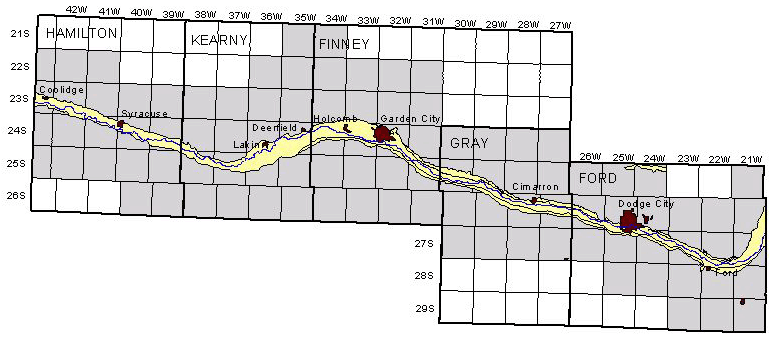
Figure 1--Location of the area of the Upper Arkansas River Corridor Study within the 5-county region. The study area is shaded.
Many studies have dealt with the geology and water resources of southwestern Kansas. Historical data for this report were obtained from the following publications: Lobmeyer and Sauer (1974) [Hamilton County]; McLaughlin (1943) [Hamilton and Kearny counties]; Gutentag et al. (1972a) [Kearny County]; Dunlap et al. (1985) [Kearny and Finney counties]; Meyer et al. (1969, 1970), Gutentag et al. (1972b), and Johnson and Arbogast (1993a, b) [Finney County]; Latta (1944) [Finney and Gray counties]; McGovern and Long (1974) [Gray County]; Waite (1942) and Spinazola and Dealy (1983) [Ford County]; Gutentag et al. (1981) [southwest Kansas]; and O'Connor and McClain (1982), Stullken et al. (1985), and Watts and Stullken (1985) [western Kansas]. Most of the information in the following sections reviewing the geology and hydrology of the study area was obtained from these publications. Many of these publications include generalized geologic cross sections, and some contain maps showing surficial and bedrock geology. The cross sections in the previous reports generally do not contain information on the lithology of the unconsolidated Tertiary and Quaternary deposits.
The project study area covers approximately 3,560 mi2 along the Arkansas River corridor from the Colorado state line to the Ford-Edwards county line in southwestern Kansas. It includes parts of Hamilton, Kearny, Finney, Gray, and Ford counties (Figure 1). The climate is semiarid, characterized by abundant sunshine, low humidity, and brisk wind movement. Mean annual precipitation ranges from less than 17 inches in the west to about 22 inches in the east.
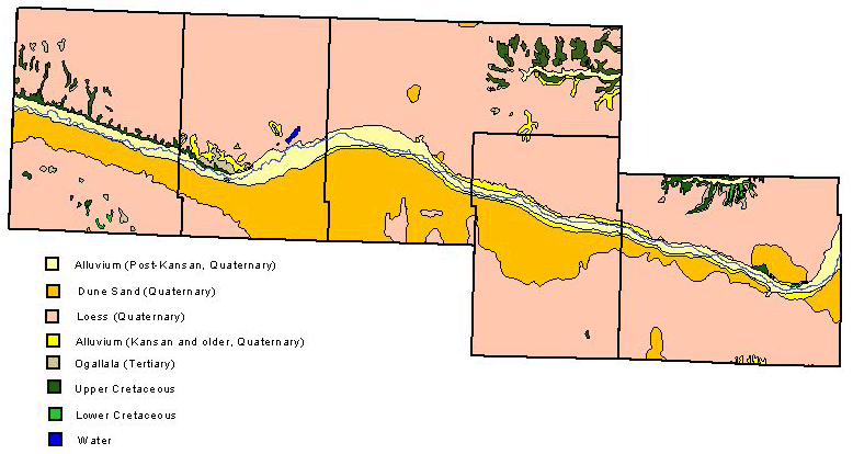
Southwestern Kansas lies in the High Plains region of the Great Plains physiographic province. The land surface in the study area generally varies from a flat upland covered with loess in the north to rolling sand dunes in the south. Loess and dune sand lie above the water table and do not supply water to wells. In most of the study area, the Arkansas River and its flood plain separate the uplands from the sand dunes (Figure 2). Bluffs or steep slopes commonly border the river valley on the north, while gentler sand hills border the valley on the south.
Figure 2--Surface geology of the Upper Arkansas River Corridor study area.
Tertiary and Quaternary deposits underlie most of the study area and range in thickness up to more than 500 feet. The saturated part of the Ogallala Formation of Pliocene age, the undifferentiated Pleistocene deposits, and the Quaternary alluvium in the Arkansas River corridor form the aquifer system in the study area. The Pliocene and undifferentiated Pleistocene deposits are hydraulically connected and lithologically similar, and are considered as one aquifer, the High Plains aquifer. In this report the High Plains aquifer is differentiated from the shallower Arkansas River alluvial aquifer. Although both aquifers are hydraulically connected to some extent, the distinction is made on the basis of differences in water levels due to a relatively impermeable zone between them. Also, the permeability is greater in the Arkansas River alluvium. The Arkansas River meanders through the study area and interacts hydraulically with the aquifer system. The surface of the Cretaceous bedrock defines the lower limit of the aquifer system. In parts of the study area, the Dakota aquifer may be considered as part of the aquifer system, but it will not be discussed in this report.
Consolidated rocks of Cretaceous age, which underlie the unconsolidated Tertiary and Quaternary deposits, are referred to as bedrock in this report. As a rule, undifferentiated Lower Cretaceous rocks form the bedrock surface in the southern part of the study area, and Upper Cretaceous rocks in the north. Upper Cretaceous rocks, which may include Graneros Shale, Greenhorn Limestone, Carlile Shale, and Niobrara Chalk, subcrop in normal stratigraphic sequence as the elevation of the bedrock surface rises to the north. The dip of the Cretaceous formations is northeastward. Upper Cretaceous rocks crop out in areas where streams have eroded the Tertiary and Quaternary deposits, particularly north of the Arkansas River (Figure 2). The Dakota Formation (Lower Cretaceous) crops out in isolated areas.
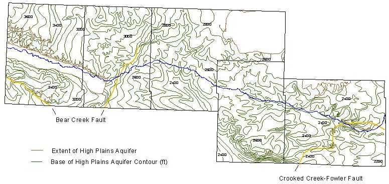
The configuration of the bedrock surface, shown in Figure 3, indicates an east- to southeast-trending drainage system that has been altered by faulting and subsidence associated with dissolution of Permian evaporites. The major structural features on the bedrock surface are the Bear Creek fault in Hamilton and Kearny counties and the Crooked Creek-Fowler fault in Ford County. These faults, which are result of dissolution of salt evaporites and subsidence during late Tertiary or early Quaternary time, have a vertical displacement of as much as 250 feet. The area of subsidence in the study area is bounded on the west by the Bear Creek fault and on the east by the Crooked Creek-Fowler fault. The faults are partially defined on the present land surface by a line of sinkholes and filled sinks, suggesting that dissolution of the evaporites is continuing (O'Connor and McClain, 1982). Between the Bear Creek and Crooked Creek-Fowler faults, the irregular bedrock surface slopes at about 13.5 feet per mile. The gradient increases near the Crooked Creek-Fowler fault.
Figure 3--Configuration of the base of the High Plains aquifer in the Upper Arkansas River Corridor study area (after USGS, 1985).
The sandstones of the Dakota aquifer (Lower Cretaceous) may be a source of water in some locations (see Macfarlane et al., 1989). Upper Cretaceous rocks are relatively impermeable and yield little or no water to wells. Some solution channels are present in the Niobrara Chalk, but they are not believed to constitute a continuous aquifer. Table 1 provides a generalized description of the geologic formations in the study area and their water-bearing properties.
Table 1--Generalized section of geologic formations and their water-bearing properties (from Gutentag et al., 1981). The classification and nomenclature of the stratigraphic units used in this report are those of the Kansas Geological Survey and differ somewhat from those of the U.S. Geological Survey
| System | Series | Stratigraphic unit |
Thickness, Feet |
Physical character | Water supply |
|---|---|---|---|---|---|
| Quaternary | Pleistocene | Alluvium | 0-80 | Stream-laid deposits ranging from silt and clay to sand and gravel that occur along principal stream valleys. | Yields to wells range from 500 to more than 1,000 gal/min in the Arkansas River valley; 50 to 500 gal/min in the Pawnee River valley; and 50 to 1,000 gal/min in the Cimarron River valley. |
| Dune sand | 0-75 | Fine to medium quartzose sand with small amounts of clay, silt, and coarse sand formed into mounds and ridges by the wind. | Lies above the water table and does not yield water to wells. The sand has a high infiltration rate and is important as area of ground- water recharge. | ||
| Loess | 0-45 | Silt with subordinate amounts of very fine sand and clay deposited as windblown dust. | Lies above the water table and does not yield water to wells. Serves as minor area of ground-water recharge. | ||
| Undifferentiated deposits | 0-550 | Sand, gravel, silt, clay, and caliche overlie Ogallala Formation when both formations are present;composite of stream-laid and windblown deposits. | The sand and gravel of the undifferentiated Pleistocene deposits and the Ogallala Formation are the | ||
| Tertiary | Pliocene | Ogallala Formation | 0-500 | Poorly sorted clay, silt, sand, and gravel generally calcareous; when cemented by calcium carbonate, Forms caliche layers or mortar beds. | Principal water-bearing deposits in the area. Yields range from 100 to 3,100 gal/min. |
| Cretaceous | Upper Cretaceous | Niobrara Chalk | 0-250 | Upper unit (Smoky Hill Chalk Member)--yellow to orange-yellow chalk and light- to dark-gray beds of chalky shale. Lower unit (Fort Hays Limestone Member)--consists of a white to yellow massive chalky limestone: contains thin beds of dark-gray chalky shale. | Generally not considered an aquifer. Initially (1968-72), yielded 500 to 2,500 gal/min to wells in northern Finney and eastern Kearny Counties where the Fort Hays Limestone Member has been honeycombed by fractures and solution openings. Because of increased irrigation development, yields have been reduced by 100 to as much as 2,000 gal/min. |
| Carlile Shale | 0-330 | Upper unit consists of a dark-gray to blue-black noncalcareous to slightly calcareous shale that locally is interbedded with calcareous silty very fine-grained sandstone. Lower part consists of very calcareous dark-gray shale and thin gray interbedded limestone layers. | Sandstone in upper part may yield 5 to 10 gal/min to wells. | ||
| Greenhorn Limestone | 0-200 | Chalky light yellow-brown shale with thin-bedded limestone. Dark-gray calcareous shale and light-gray thin-bedded limestone; contains layers of bentonite. | Not known to yield water to wells in southwestern Kansas. | ||
| Graneros Shale | 0-130 | Dark-gray calcareous shale interbedded with black calcareous shale; contains thin beds of bentonite. Also contains thin-bedded gray limestone and fine-grained silty sandstone layers. | Not known to yield water to wells in southwestern Kansas. | ||
| Lower Cretaceous | Undifferentiated rocks | 0-450 | Upper unit (Dakota Formation)--brown to gray fine- to medium-grained sandstone; interbedded with gray sandy shale and varicolored shale; contains lignite lenses (0-160 feet). Middle unit (Kiowa Formation)--dark-gray to black shale; interbedded with light yellow-brown and gray sandstone (0-150 feet). Lower unit (Cheyenne Sandstone)--gray and brown very fine-to medium-grained sandstone; interbedded with dark-gray shale (0-125 feet). | The sandstone units commonly yield from 50 to 500 gal/min to wells. Yields of more than 1,000 gal/min are reported in a few areas. Water may be more mineralized in the lower unit than in the upper unit. | |
| Jurassic | Upper Jurassic | Undifferentiated rocks | 0-350 | Dark-gray shale; interbedded with grayish-green and bluish-green calcareous shale. Contains very fine- to medium-grained silty sandstone and some thin limestone beds at the base. | In Morton and Stanton Counties, sandstone beds are yielding in combination with the overlying Lower Cretaceous units. In the northernmost counties where the aquifer is deepest, the water may be mineralized. |
| Permian | Upper Permian | Big Basin Formation | 0-160 | Brick-red to maroon siltstone and shale; contains very fine-grained sandstone. | Where not highly mineralized, may yield small quantities of usable water for domestic and stock purposes. |
| Day Creek Dolomite | 0-80 | White to pink anhydrite and gypsum; contains interbedded dark-red shale. | Solution cavities have yielded large quantities (300 to 1,000 gal/min) of high sulfate water to wells in Morton County. | ||
| Whitehorse Formation | 100-350 | Red to maroon fine-grained silty sandstone, siltstone, and shale. | Fresh to highly mineralized water. Not known to yield significant amounts of water to wells in southwestern Kansas. | ||
| Lower Permian | Dog Creek Formation | 15-60 | Maroon silty shale, siltstone, very fine sandstone, and thin layers of dolomite and gypsum. | Not known to yield significant amounts of water to wells in southwestern Kansas. Water probably highly mineralized. | |
| Blaine Formation | 20-150 | Generally consists of four gypsum and anhydrite beds separated by red shale; contains bedded halite at some sites. | Not known to yield significant amounts of water to wells in southwestern Kansas. Water probably highly mineralized. |
Thick, layered unconsolidated sediments of Tertiary and Quaternary age underlie most of the study area. The principal sources of water are sand and gravel layers in Pliocene (Ogallala Formation) and undifferentiated Pleistocene deposits. The unconsolidated Pliocene and Pleistocene deposits are hydraulically connected and lithologically similar, and are considered as one aquifer, the High Plains aquifer. The Quaternary alluvium in the Arkansas River valley is also a source of water and will be discussed in the following section. The Arkansas River, the Quaternary alluvial aquifer, and the underlying High Plains aquifer are hydraulically connected.
The High Plains aquifer consists of a heterogeneous assortment of alluvial sediments. Individual beds of silt, clay, sand, gravel, and caliche generally are not continuous and within very short distances may grade laterally or vertically into material of different composition. The largest water yields are obtained from the coarser materials, generally in the lower part of the aquifer. Where the aquifer has been divided at aquifer test sites into the Pliocene Ogallala Formation and the undifferentiated Pleistocene deposits, the sand and gravel beds of the Ogallala contain a greater amount of interbedded and mixed silt, clay, and caliche than do those of Pleistocene age (Meyer et al., 1970).
The Ogallala Formation was deposited by east to southeast flowing streams. The source material was erosional debris from the Rocky Mountains, and exposed sedimentary rocks of southeastern Colorado and western Kansas. The pre-Ogallala surface was a Cretaceous southeastward-sloping erosional base, which was gradually buried by Ogallala sediments, forming an alluvial plain. The sediment deposition by braided streams created a discontinuous, heterogeneous assortment of alluvial sediments. The Ogallala Formation consists primarily of silt, sand, gravel, and clay. The sediments may be loosely consolidated or tightly cemented by calcium carbonate to form a very compact "mortar bed" that resembles concrete. Caliche is common and occurs as cementing material, pipy concretions, nodules, or irregular beds. In some places, the Ogallala is capped by a hard limestone bed, often referred to as the "algal limestone."
The undifferentiated Pleistocene deposits are the result of filling in of valley cuts in the Ogallala Formation. A heterogeneous mixture of coarse-grained channel sediment and fine-grained stream or lake sediment was deposited by braided streams. These deposits consist primarily of unconsolidated sand and gravel, interbedded with clay, silt, and local deposits of volcanic ash. The coarse-grained deposits commonly are not cemented with caliche, as they are in the Ogallala. Sand is generally the most abundant material. Similar to the Ogallala, the Pleistocene deposits generally are poorly sorted, and individual layers are discontinuous.
Because the aquifer consists of alternating lenses of fine- and coarse-grained sediments, ground-water movement may be retarded vertically and laterally. Further, the water-yielding capacity varies widely and water may be unconfined or semiconfined. Ground-water flow is mainly eastward in the study area. The aquifer system is recharged by infiltration of precipitation and irrigation water, by seepage of water from the Arkansas River and irrigation canals, and by underflow from adjacent areas. Discharge from the aquifer is by underflow eastward, by transpiration and evaporation in areas of shallow water table, and by wells. Since the 1970's, baseflow to the river and ground-water evapotranspiration have been practically nonexistent (Dunlap et al., 1985). Today the discharge is primarily by wells.
The thickness of the unconsolidated deposits varies greatly due mostly to the uneven bedrock surface. The greatest sediment thicknesses are found between the Bear Creek and Crooked Creek-Fowler faults (Figure 3). Thicknesses may change by as much as 250 feet across the fault zones. The thickness of the Pliocene and Pleistocene sediments increases from north to south, with the greatest thicknesses, more than 500 feet, in parts of southern Kearny, Finney, and Gray counties. Areas of greatest thickness overlie ancient stream channels carved into the bedrock surface.
West of the Bear Creek fault, the Arkansas River alluvium rests on Cretaceous bedrock, and the High Plains aquifer is not present. Water may be obtained from the Arkansas River alluvium (however its quality may be poor) or from underlying sandstones in the Dakota aquifer. The thickness of Pliocene and Pleistocene deposits elsewhere in Hamilton County is extremely variable. The greatest sediment thicknesses of over 200 feet are found in the northeast part of the county and in the extreme southwest region south of the Bear Creek fault. In other parts of Hamilton County, little water is available from the unconsolidated sediments.
The thickness of Tertiary and Quaternary deposits in Kearny County ranges from a few feet to about 500 feet. From west to east across the Bear Creek fault zone there is a saturated thickness increase of more than 200 feet. The southeast part of the county has the greatest saturated thickness. Although the lithology of the deposits differs from one area to another, Gutentag et al. (1972a) found a general relationship between saturated thickness and well yield.
In Finney County there is a general increase in saturated thickness from north to south. The unconsolidated Tertiary and Quaternary sediments range in thickness from a few feet in the northeast to more than 500 feet in the southwest.
Dunlap et al. (1985) separated an upper and lower aquifer in Kearny and Finney counties with a confining layer for modeling purposes. The lower aquifer consisted of undifferentiated Pliocene or Miocene and Pleistocene deposits. The confining zone consisted of fine-grained Lower Pleistocene deposits. The upper layer was composed of coarse materials of Pleistocene age. The model also included the Arkansas River valley aquifer composed of Pleistocene and Holocene sediments. The confining zone ranged from near zero to about 200 feet thick. The authors noted that individual clay and silt lenses were difficult to correlate from one location to another.
In Gray County, sediment thicknesses greater than 500 feet occur in the southwestern part of the county. Minimal thicknesses occur in an area of southeastern Gray County due to a bedrock high.
The thickness of unconsolidated sediments in Ford County generally is less than about 200 feet, but may exceed 500 feet on the downthrown side of the Crooked Creek-Fowler fault (Spinazola and Dealy, 1983) where buried sinkholes or depressions in the bedrock surface occur. The deposits are much thinner east of the fault.
It is important to recognize the difficulty in characterizing the aquifer system because of its heterogeneity. Nearly all previous reports emphasize that individual beds and lenses are not continuous over wide areas. As Meyer et al. (1970) reported, "...the individual beds pinch out or grade, almost imperceptibly, both laterally and vertically, into finer or coarser material of another bed or lense." Because of the heterogeneity, most of the reports recommend test drilling for locating a large-capacity well.
The Arkansas River alluvial sediments are the most permeable water-bearing deposits in the study area. The alluvial material underlying the Arkansas River valley consists of coarse-grained deposits of Pleistocene age overlain by fine-grained deposits of Holocene age. The material is poorly sorted and may grade into material of different composition within short distances both laterally and vertically. Clay is generally found at or near the base of the alluvium. The alluvial and terrace deposits typically extend beyond the valley beneath the dune sand south of the river.
West of the former town of Hartland in Kearny County (just west of the Bear Creek fault) the alluvium overlies Cretaceous bedrock. East of Hartland the alluvium is underlain by undifferentiated Pliocene and Pleistocene deposits. The former town of Hartland is located where the course of the Arkansas River changes from a southeast to a northeast direction (see Figures 2 and 3). The Arkansas River valley ranges in width from 2 to 3 miles in Hamilton County, and is less than 1 mile at its narrowest near Hartland. East of Hartland the valley broadens and attains a maximum width of about 5 miles near Lakin (Figures 1 and 2).
In the western part of the study area the thickness of the alluvium ranges from about 10 feet southwest of Hartland to about 100 feet beneath dune sand a few miles south of the river near Coolidge (McLaughlin, 1943). Generally, the thickness in Hamilton County is between 50 and 60 feet and in Kearny County is between 40 and 50 feet.
In Finney County the width of the Arkansas River alluvium ranges from 1 mile in the east to 3.5 miles west of Garden City, and averages about 2 miles. The average thickness of the alluvium in Finney County is about 40 feet (Meyer et al., 1970). In Gray County the alluvial valley is relatively narrow, and has a consistent width of about 2.5 miles. The thickness varies considerably both along and across the valley in Finney and Gray counties.
The width of the alluvial valley in Ford County ranges from about 2 miles along the western border to about 4 miles across the eastern border. The valley widens east of the Crooked Creek-Fowler fault, where the alluvium rests unconformably on Cretaceous bedrock. Thickness of the alluvium ranges from about 15 feet in the eastern part of the county to about 40 feet in the central and western parts, and may be 50 feet or more in places (Waite, 1942).
Geologic data used in producing cross sections were obtained from lithologic logs of water wells (WWC-5 forms filed by well drillers since 1975), wells and test holes published in previous reports of the U.S. Geological Survey and Kansas Geological Survey, and monitoring wells and test holes drilled for the UARC study. Cross sections are presented in Plates 1- 3; lithologic logs are available from the authors. The goal was to develop procedures that would allow electronic storage, processing, and display of the lithologic data. This method could allow easier printing of copies as needed and updating based on new lithologic data.
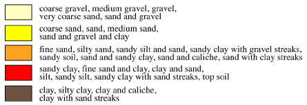
The first step taken for electronic handling of data and production of displays was the simplification of the wide variety of lithologic descriptions into general categories. Each described material from the lithologic logs was assigned a numerical geologic code from 1 to 5, based on relative permeability (see Young et al., 1997). The lithologic logs were then transformed into numerical logs based on the geologic codes. The materials were then assigned one of five colors (light to dark) based on relative permeability. The range of colors corresponding to the different (permeability) materials is shown in Figure 4 and on each of the cross sections.
Figure 4--Material identification color codes.
The colors representing the numerical logs were entered into a Microsoft Excel spreadsheet. Each column in the spreadsheet represents either a borehole or space between the boreholes as appropriate for hardcopy production. Each spreadsheet row represents a uniform depth interval in the borehole. An interval of one foot was used for this study. Thus, geologic intervals of more than one foot occupy multiple adjoining rows (or cells) in the column for that borehole. For example, five feet of clay is represented by the dark brown color in five adjoining cells in the appropriate column. Once a cross section was completed, the Excel file was imported as a postscript file into Adobe Illustrator for final editing.
A primary source of uncertainty is the location of a well or test hole. Locations listed on WWC-5 sheets and test hole logs are sometimes in question. Further, elevations are normally not listed on WWC-5 forms, so an incorrect location can result in the wrong estimated elevation. A substantial amount of effort went into ensuring that locations (and therefore elevations) were as accurate as possible. For example, on WWC-5 forms, legal locations were compared with distance and direction from nearest town or city. Also county rural phone books were consulted for landowner/tenant information and compared with owner of the well listed on the WWC-5 sheet.
Elevations were estimated from 7.5 minute topographic maps with scale a of 1:24000 and contour intervals of 5 or 10 feet. Estimated elevations in the alluvial valley, which is relatively flat, are usually within 5 feet and probably always within 10 feet of the actual elevation (assuming accurate locations), but the uncertainty increases greatly on or near terraces or bluffs, and in dune sand. Fortunately, the focus is on the alluvial valley, and most wells used in the cross sections are located in the valley.
Published logs of test holes were normally used where available. There is typically a higher level of confidence as to the elevation, location, and accuracy of the lithologic descriptions on these logs. Additionally, virtually every WWC-5 form was examined in the townships studied. Generally only wells that went to bedrock were included in sections. It became apparent that the quality and consistency of the information on the WWC-5 forms varied depending on the driller or drilling company. Logs by Henkle, Minter-Wilson, and Clarke were generally consistent, and where available were often favored over some of the others, based on the character of the lithologic reporting.
An accurate depth to bedrock was not always easy to determine from WWC-5 forms. Logs of test holes have the advantage that the geologic formation is normally listed. For example, some Cretaceous (bedrock) materials may actually appear as a clay or clay-shale. Therefore, what appears near the bottom of a WWC-5 log as a hard clay may actually be Cretaceous bedrock. If enough nearby information was available to suggest with confidence that the clay was actually Cretaceous material, then the column was truncated at the top of the clay. Thus, the bottom of the columns in the sections provides an approximation of the bedrock surface underlying the wells, but is subject to uncertainties.
Geologic cross sections characterizing the lithology along the Upper Arkansas River corridor are presented in Plates 1, 2 and 3. The corresponding lithologic logs (copies of WWC-5 forms and test hole logs) are available from the authors. Locations of the wells used for the cross sections are shown in Figures 5 and 6 and listed in Tables 2, 3 and 4. The geologic sections in this report supercede those in previous project reports.
Figure 5--Locations of wells and test holes used in west-east aluvial valley sections.
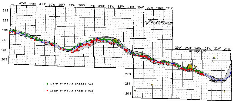
Figure 6--Locations of wells and test holes used in north-south sections.
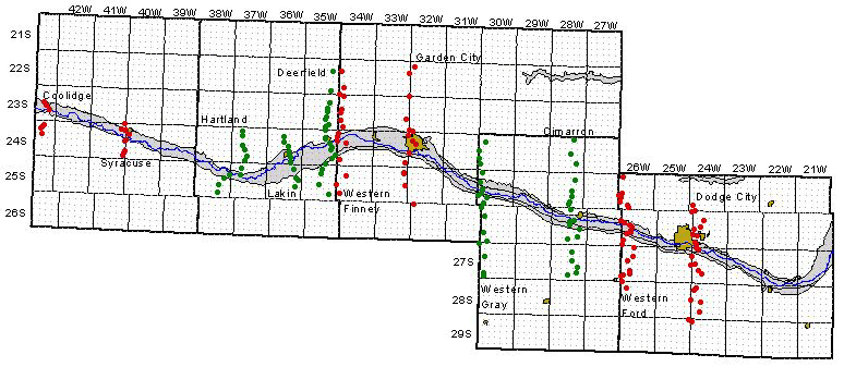
Table 2--Locations of wells and test holes used in north of the Arkansas River section (Plate 1).
| Hamilton County | Finney County | Ford County | ||
|---|---|---|---|---|
| 23S 43W 21 DAB | 24S 34W 07 BBB | 26S 26W 17 DDD | ||
| 23S 43W 22 BCC | 24S 34W 03 DDC | 26S 26W 16 CCD | ||
| 23S 43W 23 ACC | 24S 34W 11 AC | 26S 26W 22 CAD | ||
| 23S 43W 24 AC | 24S 34W 12 B | 26S 26W 27 ABA | ||
| 23S 43W 24 DDB | 24S 33W 06 CC | 26S 26W 26 BAB | ||
| 23S 42W 27 DDB | 24S 33W 08 BBD | 26S 25W 29 CCC | ||
| 23S 42W 35 AAA | 24S 33W 09 BCB | 26S 25W 28 CDD | ||
| 23S 41W 32 CCB | 24S 33W 16 BBB | 26S 25W 28 DDC | ||
| 24S 41W 05 BB | 24S 33W 10 BAA | 26S 25W 34 BBC | ||
| 24S 41W 04 DCB | 24S 33W 11 BAB | 26S 25W 35 ABB | ||
| 24S 41W 03 CDB | 24S 33W 12 CCA | 26S 24W 31 ADD | ||
| 24S 41W 11 BD | 24S 32W 07 DCC | 27S 24W 06 AAA | ||
| 24S 41W 11 ABA | 24S 32W 07 DAB | 27S 24W 04 BC | ||
| 24S 40W 07 D | 24S 32W 17 BAA | 27S 24W 04 BDC | ||
| 24S 40W 08 CCC | 24S 32W 21 BBB | 27S 24W 04 CAD | ||
| 24S 40W 17 C | 24S 32W 22 BAA | 27S 24W 03 AC | ||
| 24S 40W 16 CBC | 24S 32W 23 CCC | 27S 24W 02 CCB | ||
| 24S 40W 15 CBB | 24S 32W 26 BAB | 27S 24W 12 B | ||
| 24S 40W 15 DDA | 24S 32W 25 DDD | 27S 23W 07 CBA | ||
| 24S 40W 23 ABB | 25S 31W 13 CD | |||
| 24S 39W 27 B | ||||
| 24S 39W 25 DBD |
| Kearny County | Gray County | |
|---|---|---|
| 25S 38W 12 A | 25S 30W 20 BBC | |
| 25S 37W 08 DDC | 25S 30W 22 DC | |
| 25S 37W 08 DDD | 25S 30W 22 D | |
| 25S 37W 09 DDD | 25S 30W 24 BDD | |
| 25S 37W 10 CDC | 25S 30W 25 BAA | |
| 25S 37W 11 CC | 25S 29W 28 BDA | |
| 25S 37W 11 CCA | 25S 29W 28 ACD | |
| 25S 37W 11 DDC | 25S 29W 28 DDA | |
| 25S 36W 06 CAC | 26S 29W 02 ABB | |
| 24S 36W 31 DDC | 26S 29W 01 BD | |
| 24S 36W 33 BAB | 26S 28W 12 ADD | |
| 24S 36W 26 C | 26S 27W 07 BBC | |
| 24S 36W 26 BCB | 26S 27W 08 DBB | |
| 24S 36W 23 CCC | 26S 27W 09 DBC | |
| 24S 35W 17 A | 26S 27W 09 DCB | |
| 24S 35W 15 BAC | 26S 27W 10 DDD | |
| 24S 35W 11 CBB |
Table 3--Locations of wells and test holes used in south of the Arkansas River section (Plate 2).
| Kearny County | Gray County | Ford County | ||
|---|---|---|---|---|
| 25S 38W 11 CB | 25S 30W 19 DDD | 26S 26W 19 AA | ||
| 25S 37W 18 BBB | 25S 30W 27 BC | 26S 26W 20 ACA | ||
| 25S 37W 14 ACC | 25S 30W 26 A | 26S 26W 20 D | ||
| 25S 37W 24 CBB | 25S 30W 25 C | 26S 26W 27 BBB | ||
| 25S 36W 18 D | 25S 30W 25 D | 26S 26W 36 BDB | ||
| 25S 36W 17 ACB | 25S 29W 30 C | 26S 26W 36 ADD | ||
| 25S 36W 09 CBB | 25S 29W 30 D | 26S 25W 31 AB | ||
| 25S 36W 16 ABC | 25S 29W 29 C | 26S 25W 32 BBB | ||
| 25S 36W 04 DAA | 25S 29W 29 D | 26S 25W 32 CC | ||
| 25S 36W 03 BAD | 25S 29W 28 C | 27S 25W 05 A | ||
| 24S 36W 35 C | 25S 29W 33 AA | 27S 25W 04 BCD | ||
| 24S 36W 35 DDA | 26S 29W 03 B | 27S 25W 03 BAD | ||
| 24S 35W 30 CCB | 26S 29W 03 A | 26S 25W 34 DDD | ||
| 24S 35W 29 C | 26S 29W 02 DBC | 26S 25W 35 CDD | ||
| 24S 35W 29 A | 26S 28W 07 CAC | 26S 25W 36 BDB | ||
| 24S 35W 28 ABB | 26S 28W 07 ADB | 27S 25W 01 AAA | ||
| 24S 35W 27 C | 26S 28W 10 CCC | 27S 24W 05 BCD | ||
| 24S 35W 27 D | 26S 28W 10 DDD | 27S 24W 05 BDD | ||
| 24S 35W 23B | 26S 28W 14 ACA | 27S 24W 04 CBC | ||
| 24S 35W 14 A | 26S 27W 18 BCC | 27S 24W 04 DA | ||
| 24S 35W 24 BCB | 26S 27W 16 B | 27S 24W 03 CAB | ||
| 24S 35W 13 CCD | 26S 27W 15 DCC | 27S 24W 10 ABB | ||
| 24S 35W 13 AAA | 27S 24W 10 AAA | |||
| 27S 24W 11 BBD | ||||
| 27S 24W 12 CC | ||||
| 27S 24W 13 BAD | ||||
| 27S 24W 13 AAD | ||||
| 27S 23W 18 BDC | ||||
| 27S 23W 18 DBB | ||||
| 27S 23W 17 CCC |
| Hamilton County | Finney County | |
|---|---|---|
| 23S 43W 28 DC | 24S 34W 07 CCC | |
| 23S 43W 25 BBB | 24S 34W 17 ABD | |
| 23S 43W 36 AAA | 24S 34W 08 AAB | |
| 24S 41W 10 DD | 24S 34W 09 BDC | |
| 24S 40W 19 BBB | 24S 34W 10 C | |
| 24S 40W 18 CCA | 24S 34W 14 B | |
| 24S 39W 30 ADA | 24S 34W 13 AAC | |
| 24S 39W 27 DDA | 24S 33W 22 A | |
| 24S 39W 26 CDD | 24S 33W 23 A | |
| 24S 39W 36 CBB | 24S 32W 19 CAB | |
| 24S 39W 36 C | 24S 32W 26 C | |
| 25S 31W 05 C | ||
| 25S 31W 08 A | ||
| 25S 31W 09 B | ||
| 25S 31W 09 C | ||
| 25S 31W 09 DBC |
Table 4--Locations of wells and test holes used in north-south sections (Plate 3).
| Coolidge | Deerfield | Garden City | ||
|---|---|---|---|---|
| 23S 43W 14 CC | 22S 35W 14 AAA | 22S 32W 06 DD | ||
| 23S 43W 23 ACC | 22S 35W 35 ADB | 22S 33W 13 AAA | ||
| 23S 43W 25 BBB | 23S 35W 11 ACD | 23S 32W 06 BBB | ||
| 24S 43W 02 CAC | 23S 35W 14 BDC | 23S 33W 24 DC | ||
| 24S 43W 02 CCC | 23S 35W 14 CDC | 23S 32W 31 C | ||
| 24S 43W 10 A | 23S 35W 23 CCB | 23S 32W 31 DDD | ||
| 24S 43W 14 BBC | 23S 35W 27 AAD | 24S 32W 06 CBA | ||
| 23S 35W 35 ABB | 24S 32W 07 DA | |||
| Syracuse | 23S 35W 34 DAA | 24S 32W 17 BAA | ||
| 23S 41W 36 DDD | 24S 35W 02 BBB | 24S 32W 19 CAB | ||
| 24S 41W 01 CDD | 24S 35W 11 BC | 24S 33W 36 A | ||
| 24S 41W 12 AAA | 24S 35W 11CBB | 25S 33W 01 DC | ||
| 24S 40W 07 BBD | 24S 35W 14 A | 25S 33W 12 AB | ||
| 24S 40W 07 D | 24S 35W 13 CCD | 25S 33W 24 AA | ||
| 24S 40W 18 CCA | 24S 35W 24 BCB | 26S 32W 06 AB | ||
| 24S 40W 19 BBB | 24S 35W 25 A | |||
| 24S 40W 30 CBA | 24S 35W 25 C | Western Gray County | ||
| 24S 40W 30 CCC | 24S 35W 35 C | 24S 30W 08 B | ||
| 24S 41W 36 ADB | 25S 35W 03 D | 24S 30W 18 CAC | ||
| 25S 35W 10 AC | 24S 30W 30 BAB | |||
| Hartland | 25S 35W 22 BCA | 24S 30W 31 ABB | ||
| 24S 37W 04 CBC | 25S 35W 26 DDD | 25S 30W 06 ADD | ||
| 24S 37W 08 ADD | 25S 30W 18 ABB | |||
| 24S 37W 21 BBB | Western Finney County | 25S 30W 20 BBC | ||
| 24S 37W 21 CD | 22S 34W 18 ABB | 25S 30W 19 DDD | ||
| 24S 37W 28 DDD | 22S 34W 30 DDA | 25S 30W 30 BDB | ||
| 24S 37W 33 CAD | 22S 34W 31 CCD | 25S 30W 29 DAC | ||
| 25S 37W 05 DDD | 23S 34W 06 AAD | 25S 30W 32 CAC | ||
| 25S 37W 08 DDC | 23S 34W 18 ACD | 26S 30W 06 B | ||
| 25S 37W 18 BBB | 23S 34W 19 ABB | 26S 30W 07 DAB | ||
| 25S 38W 13 CBC | 23S 34W 30 AC | 26S 30W 30 A | ||
| 25S 38W 23 C | 23S 34W 32 BCC | 26S 30W 32 C | ||
| 25S 38W 35 BBB | 24S 34W 06 CAB | 27S 30W 06 BBB | ||
| 24S 34W 07 BBB | 27S 30W 17 BCB | |||
| Lakin | 24S 34W 07 CCC | 27S 30W 31 AAA | ||
| 24S 36W 10 BCC | 24S 34W 17 ABD | 27S 30W 31 DAB | ||
| 24S 36W 15 BBC | 24S 34W 30 DCC | |||
| 24S 36W 15 DDC | 25S 34W 08 D | |||
| 24S 36W 23 CCC | 25S 34W 19 B | |||
| 24S 36W 26 BCB | 25S 34W 30 D | |||
| 24S 36W 26 C | ||||
| 24S 36W 35 C | ||||
| 25S 36W 02 DDA | ||||
| 25S 36W 13 B | ||||
| 25S 36W 13 D | ||||
| 25S 36W 24 C |
| Cimarron | Western Ford County | Dodge City | ||
|---|---|---|---|---|
| 24S 28W 02 BD | 25S 26W 06 ADD | 25S 24W 30 DDD | ||
| 24S 28W 15 DDD | 25S 26W 19 A | 25S 24W 32 CCD | ||
| 24S 28W 26 DAA | 25S 26W 19 C | 26S 24W 06 BBB | ||
| 25S 28W 11 A | 25S 26W 30 ABB | 26S 24W 09 BCC | ||
| 25S 28W 23 BAC | 25S 26W 30 CDA | 26S 24W 17 ACC | ||
| 25S 28W 26 BBA | 25S 26W 32 A | 26S 24W 18 CDA | ||
| 25S 28W 27 DDD | 25S 26W 32 DAD | 26S 24W 19 C | ||
| 25S 28W 34 ACD | 26S 26W 07 CBC | 26S 24W 20 CCC | ||
| 26S 28W 03 BAD | 26S 26W 18 ABB | 26S 24W 31 ABD | ||
| 26S 28W 10 DDD | 26S 26W 17 BDD | 26S 24W 31 ADD | ||
| 26S 28W 15 BAC | 26S 26W 17 DDA | 27S 24W 06 AAA | ||
| 26S 28W 15 C | 26S 26W 17 DDD | 27S 24W 05 BCD | ||
| 26S 28W 23 ADA | 26S 26W 20 ACA | 27S 24W 07 CBA | ||
| 26S 28W 26 DBD | 26S 26W 20 D | 27S 24W 18 DCA | ||
| 26S 28W 34 BBB | 26S 26W 20 CCC | 27S 24W 19 BBB | ||
| 27S 28W 10 ACA | 26S 26W 31 BAA | 27S 24W 20 CDD | ||
| 27S 28W 15 D | 26S 26W 31 C | 27S 24W 29 AD | ||
| 27S 28W 23 DCA | 27S 26W 04 B | 28S 24W 05 CC | ||
| 27S 28W 26 DCB | 27S 26W 09 C | 28S 24W 07 A | ||
| 27S 28W 34 BBD | 27S 26W 17 CBA | 28S 24W 18 C | ||
| 27S 26W 29 A | 28S 24W 20 AAC | |||
| 27S 26W 29 D | 28S 24W 29 DC | |||
| 27S 26W 30 DCC | 29S 25W 01 AAA | |||
| 27S 26W 31 BB | 29S 24W 06 CAA | |||
| 28S 26W 06 BAA | ||||
| 28S 26W 08 BB |
The cross sections represent the most detailed characterization of the lithology in the Upper Arkansas River corridor to date. The sections generally are in agreement with information from previous publications. However, cross sections in the previous literature lacked lithologic detail and were typically based on data from test holes spaced many miles apart. The geologic sections in this report fill in gaps and add lithologic detail. They help to ascertain the location and continuity of individual lithologic units, both coarse-grained and fine-grained, and thus their potential influence on ground water and contaminant movement.
In recognition of the uncertainties discussed above, it should be noted that actual elevations and lithology may vary from those portrayed in the sections depending on the accuracy of the data reporting and materials identification. The sections are based on lithologic well logs that are subjective, and differ in quality depending on the individual driller or site geologist.
Two west-east geologic cross sections along the Arkansas River corridor were constructed, one north and one south of the Arkansas River. The North of the Arkansas River section is presented in Plate 1 and the South of the Arkansas River section is presented in Plate 2. The horizontal distance scales represent approximate west-to-east miles. Locations of wells and test holes used in the sections are listed in Tables 2 and 3 and mapped in Figure 5. Figures 7 and 8 are page-sized versions of Plates 1 and 2 that provide fuller, more generalized cross sections than the larger plates. The page-sized sections include the same data, but with equal spacing between the wells. In other words they are not scaled for horizontal distance as they are in the Plates 1 and 2. Figures 7 and 8 help to show some of the apparent continuity in lithologic units, as well as changes in bedrock elevation, that may be lost visually at the larger scale because of large spaces between some of the wells. Essentially all wells included in the west-east sections are located in the Arkansas River alluvial valley. The land surface along the Arkansas River valley slopes smoothly from west to east with a regional gradient of about 8 feet per mile.
Figure 7--Page-size version of Plate 1, Geologic Cross Section North of the Arkansas River, not scaled for horizontal distance. [An Acrobat PDF version of this figure is available.]
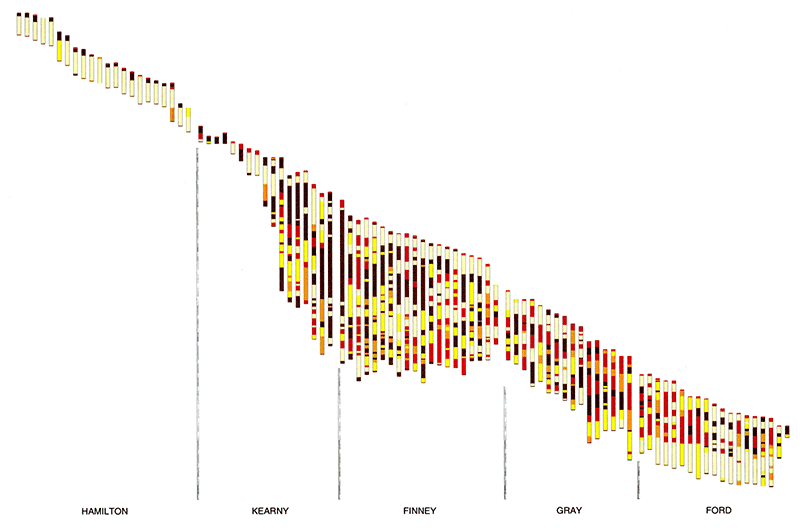
Figure 8--Page-size version of Plate 2, Geologic Cross Section South of the Arkansas River, not scaled for horizontal distance. [An Acrobat PDF version of this figure is available.]
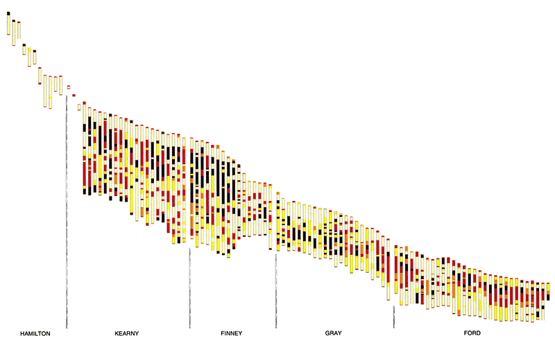
One of the most evident initial observations from the west-east sections is the continuity of the Arkansas River alluvial aquifer, especially south of the Arkansas River. Though its thickness varies considerably, its composition is relatively homogeneous through most of its extent. The alluvium is composed mainly of coarse sands and gravels capped with recent fine-grained flood-plain deposits. The exceptions to this are just west of the Bear Creek fault in western to central Kearny County, where bedrock outcrops occur, and similarly at the east end of the sections, near the Crooked Creek-Fowler fault.
The alluvial aquifer is thicker and more continuous south of the river. Actually, the maximum thickness of the Arkansas River alluvium in some areas may occur south of the river valley below the dune sand, as it does near Coolidge. South of the river the alluvium beneath the valley is thickest in parts of Hamilton County, in west-central Gray County, and west of Dodge City in western Ford County. In these latter two areas, it is difficult to distinguish the alluvial aquifer from the deeper High Plains aquifer. The coarse-grained alluvial deposits south of the river thin somewhat in the vicinities of Garden City and Dodge City.
The alluvium is thinner in general north of the river. Coarse-grained materials appear nearly absent where the river is close to the valley wall north of the river in eastern Kearny and western Finney counties, and in eastern Gray County. Of course, the closer an actual well is to the extent of the alluvium, the lower the chance of encountering thick coarse-grained alluvial deposits.
The abrupt change in the bedrock surface representing the Bear Creek fault in Kearny County is strikingly apparent in the west-east sections. The Crooked Creek-Fowler fault is also obvious at the far east end of the sections, although it is represented by only two wells in the north section and one well in the south section. Further east, Cretaceous outcrops occur north of the river valley. It is known that subsidence has occurred between the Bear Creek and Crooked Creek-Fowler faults.
The total sequence of unconsolidated sediments is obviously thickest in most of Kearny and Finney counties, and uniformly thinner east of approximately Garden City. This may be indicative that most subsidence occurred in this area, between western Kearny County (the Bear Creek fault) and eastern Finney County. The rather abrupt increase in the bedrock surface elevation from west to east in eastern Finney County is suggestive of faulting. The multitude of depressions or sinkholes on the land surface is further suggestive of a fault zone. These observations, plus a comparison of bedrock data points collected during this work with the existing base of High Plains aquifer map, suggest that remapping of the bedrock surface, including faults, is warranted.
While the heterogeneity of the High Plains aquifer is evident at a glance, a closer look reveals that the conceptual model of an upper and lower aquifer separated by a relatively impermeable layer holds true, particularly south of the Arkansas River. The relatively impermeable layer, which may consist of clay, silt, caliche and cemented sand in varying amounts, appears thinnest south of the river in eastern Finney County, western Gray County, and just west of Dodge City in western Ford County. The deep aquifer directly above the bedrock appears fairly clean and permeable--thick sand and gravel layers are present, but they may be interspersed with clay lenses and cemented zones--throughout the most of the southern section. It appears that very few fine-grained deposits are present in the deeper aquifer in Ford County.
Fine-grained sediments are more common north of the river than south of the river. Because of the abundance of fine-grained material a continuous "deep" aquifer is not nearly as evident north of the river as south of the river. In most of Kearny and Finney counties, substantial sand and gravel layers occur, but they are interspersed with many silts and clays. In eastern Kearny and western Finney counties, fine-grained deposits appear to predominate almost the entire thickness north of the river; only a few beds of coarse-grained sediments occur near the base of the Ogallala in that area.
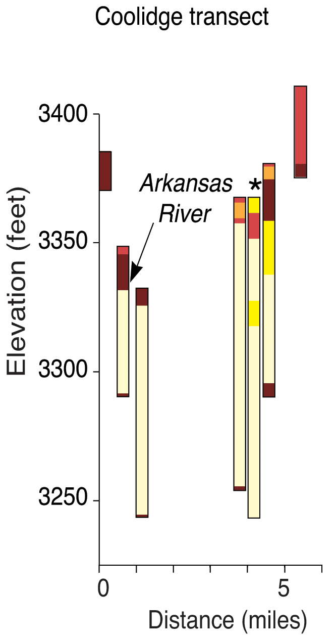
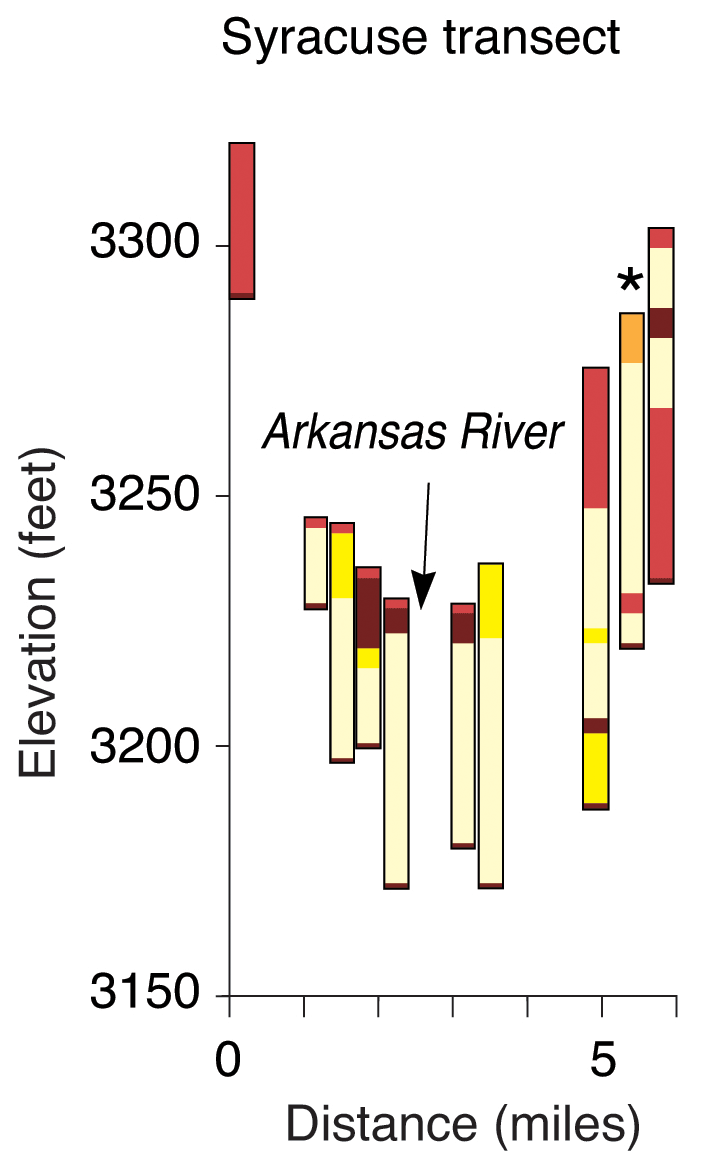
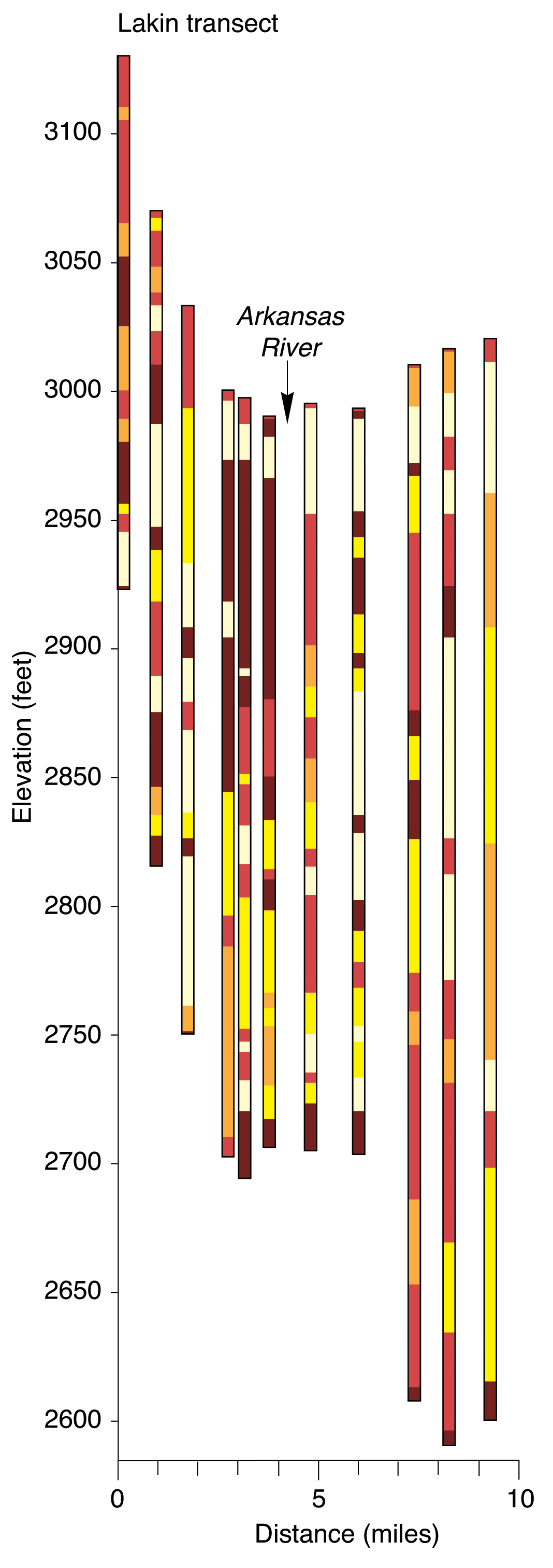
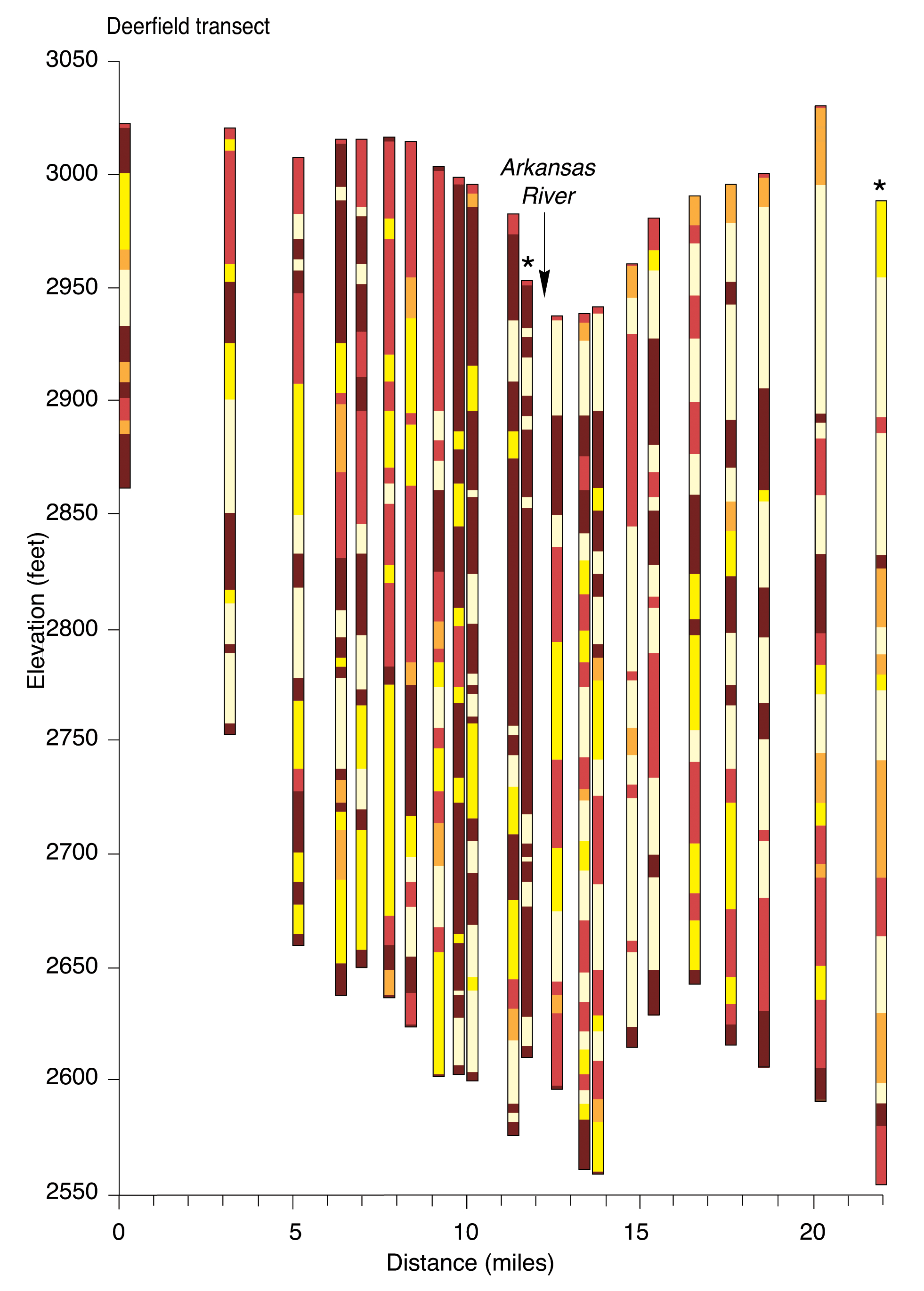
Plate 3 includes the following north-south cross sections:
The north-south sections all transect the Arkansas River. Locations of wells and test holes used in the sections are listed in Table 4 and shown in Figure 6.
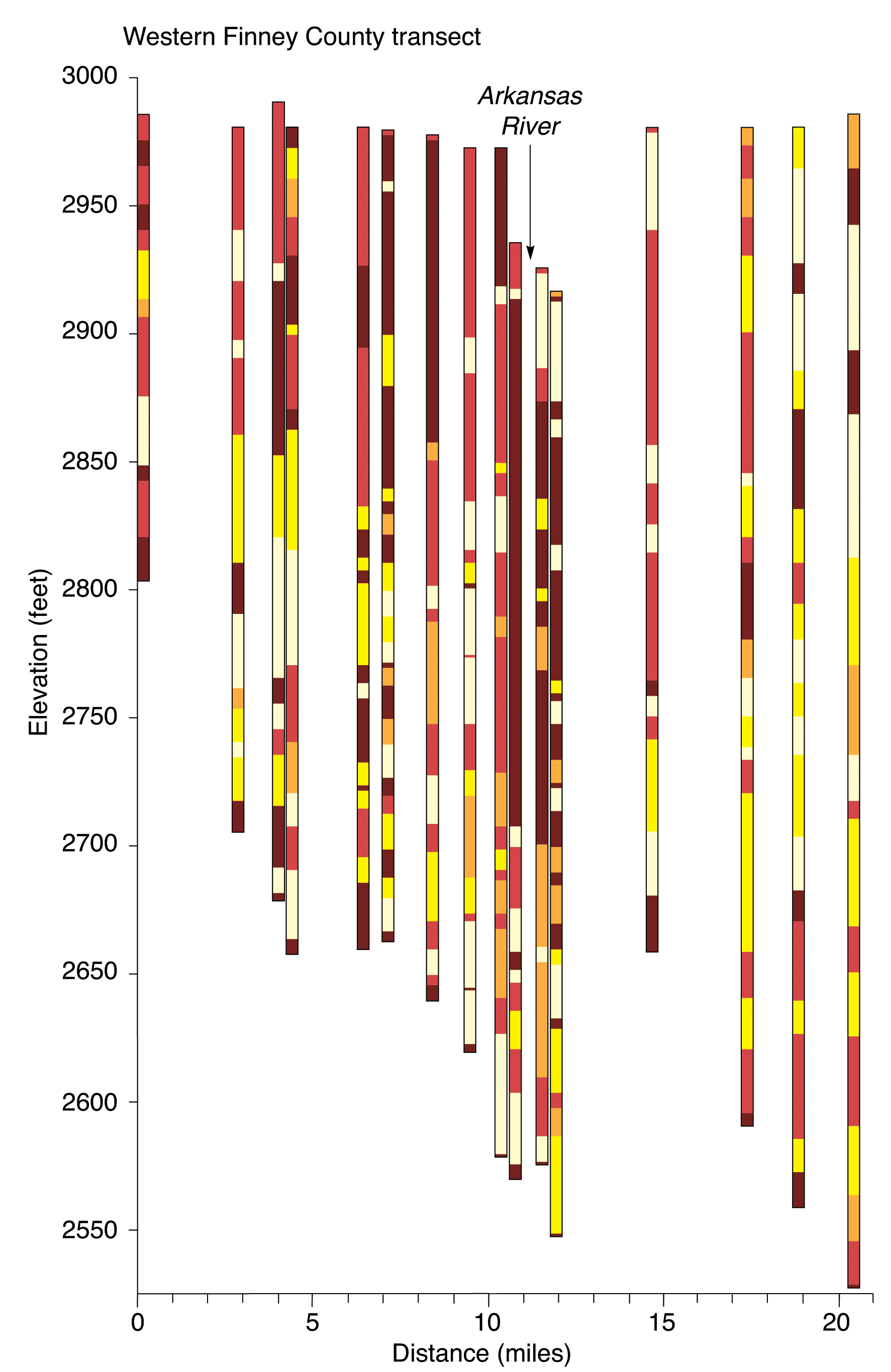
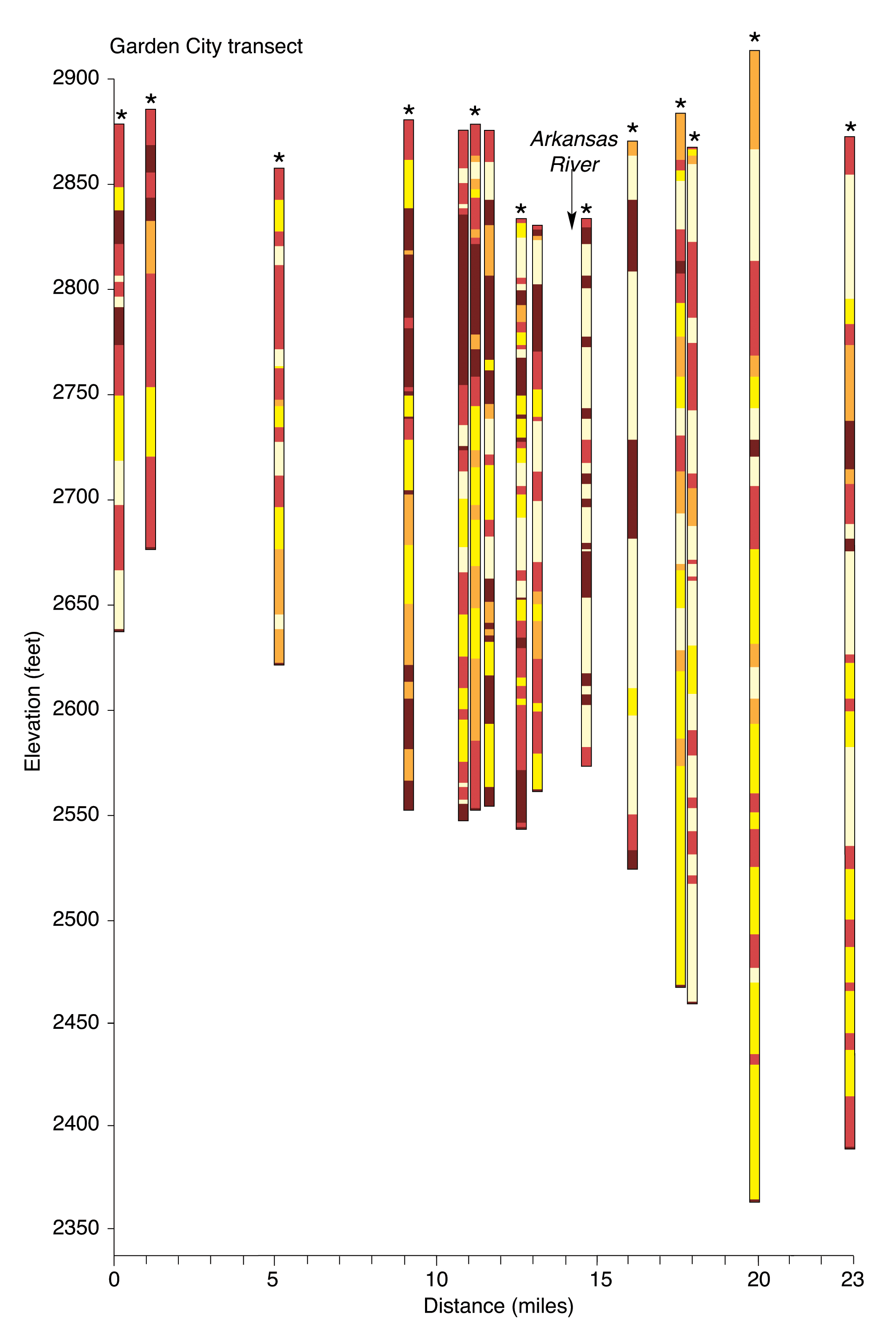
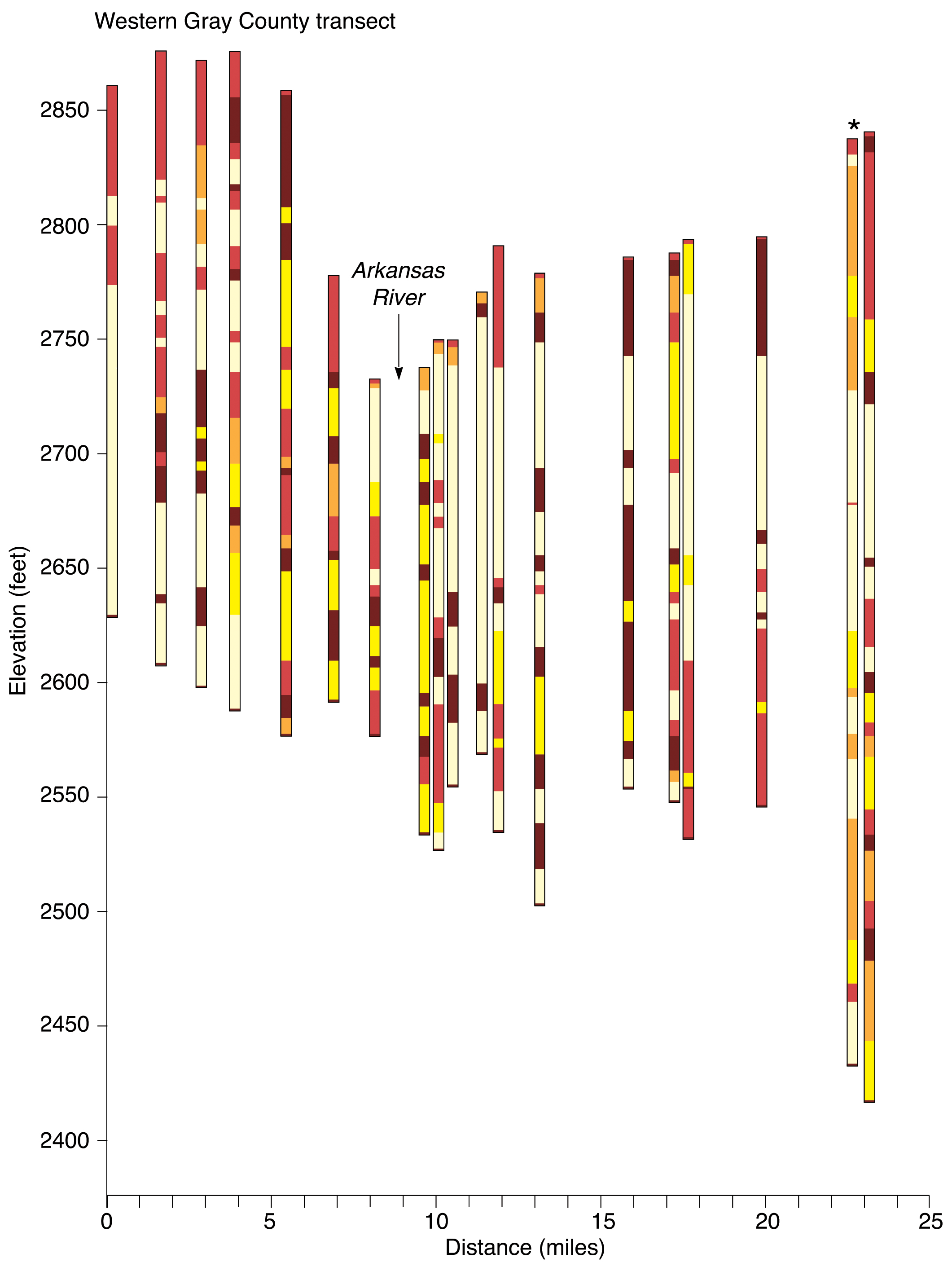
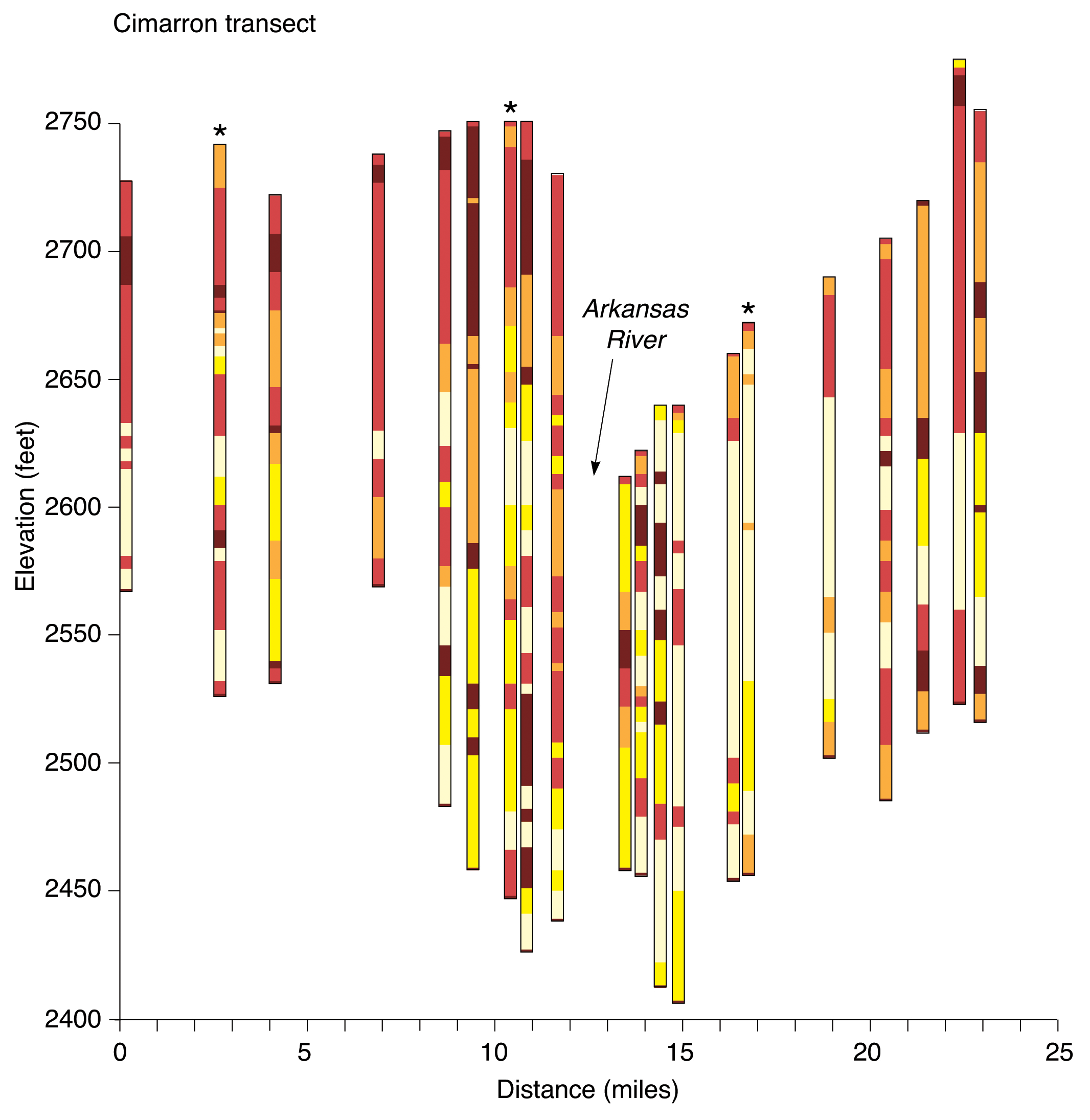
The topographies of both the land surface and the bedrock surface are much more irregular in the north-south sections compared with the west-east sections. This is primarily because the north-south sections transect ancient and present-day drainage systems that have eroded the surfaces. The land surface topography is further characterized by steep slopes or bluffs to the north of the Arkansas River valley, and gentler slopes of sand hills to the south. The alluvium in nearly all areas is composed of permeable sand and gravel, as was seen in the west-east sections. A general observation from the north-south sections is that more fine-grained deposits occur north of the river, and more coarse-grained sediments to the south. Also, the bedrock surface elevation typically drops and the thickness of unconsolidated deposits increases to the south beyond the Arkansas River valley.
The alluvium in the Coolidge, Syracuse and Hartland sections is underlain by Cretaceous bedrock. Since bedrock crops out north of the river, essentially no ground water is available from unconsolidated deposits north of the river valley in these areas. Near Coolidge the alluvium is thick below and south of the Arkansas River. In fact, the alluvium attains its greatest thickness in the Coolidge section--more than 100 feet thick--below the sand dunes a few miles south of the river. At Syracuse, the permeable alluvium is approximately 50 feet thick below the river valley.
Few well logs are available in the Arkansas River alluvium near Hartland. The few that are available show very thin and mostly fine-grained sediments. Once again, bedrock underlies these alluvial sediments and crops out in places. A relatively thick coarse-grained deposit--certainly of alluvial origin--occurs a few miles south of the river.
East of the Bear Creek fault, beginning in the Lakin section, the Arkansas River alluvium is underlain by a heterogeneous assortment of sediments that compose the High Plains aquifer. The alluvium near Lakin is approximately 40 feet thick, and is thicker south than north of the Arkansas River. Directly underlying the alluvium, particularly north of the river, is a thick relatively impermeable layer of silt and clay. There appears to be better hydraulic connection between the alluvial and High Plains aquifer south of river where coarse-grained deposits are more common. The total thickness of unconsolidated deposits is roughly 300 feet below river valley. The deposits thicken south of valley, as the elevation of the bedrock surface drops. The bedrock surface elevation increases rather sharply to the north, as the Bear Creek fault is approached.
The Deerfield and Western Finney County sections are similar, in proximity and in content. In both of these sections, the thickness of the alluvium approaches 50 feet south of river, and the total thickness of the unconsolidated deposits is greater than 350 feet below the valley. Relatively impermeable materials are present directly below the alluvium. These fine-grained sediments predominate nearly the entire thickness for a few miles north of river. Deeper permeable sand and gravel layers are interspersed with silt and clay layers beneath the alluvium south of the river. Similar sequences occur both north and south farther away from the river valley, however more coarse-grained materials are present south of the river. Thicknesses increase beyond a bedrock ridge approximately 4 to 5 miles south of the river. The bedrock ridge is most prominent in the Western Finney County section.
In the Garden City section, the thickness of the unconsolidated sediments increases from north to south. The thickness is about 300 feet below the Arkansas River valley. The alluvium is relatively thin near Garden City, but it appears to be well connected to permeable deposits of the High Plains aquifer south of the river, where thick coarse-grained deposits and relatively few silts and clays occur. The impermeable layer below the alluvium is thinner than in sections to the west; it is thicker north than south of the river. Some sand and gravel layers in the intermediate High Plains aquifer, while thicker in the south, appear to continue to the north beneath the Arkansas River valley.
The permeable alluvial deposits are relatively thick--exceeding 50 feet--both north and south of the river in the Western Gray County section. The relatively impermeable layer that typically underlies the alluvium is thin and discontinuous. The hydraulic connection between the alluvial and High Plains aquifers appears good to the south, where thick sand and gravel deposits occur. The thickest sequences of coarse sediments appear to occur at intermediate depths in the aquifer. The total thickness of unconsolidated deposits decreases to about 200 feet below the river valley, with greater thicknesses south of the river. The thickest deposits occur far south of the river. Ridges and valleys are evident on the bedrock surface.
The Arkansas River valley is narrow near Cimarron, and the alluvial deposits do not appear to be as clean and coarse-grained as is typical in other areas. The low-permeability layer appears thin and discontinuous, and the hydraulic connection between the upper and lower aquifers appears fairly good, particularly south of the river. Thick sand and gravel layers are present south of the river, which is common. Here again, the bedrock surface is undulating, a remnant of ancient stream channels eroded into the surface. A bedrock ridge occurs below and just south of the river, and depth to bedrock below the valley is less than 200 feet. A bedrock valley filled with coarse-grained sediments occurs just south of the ridge. Further south, the bedrock surface elevation increases as a bedrock outcrop is approached.
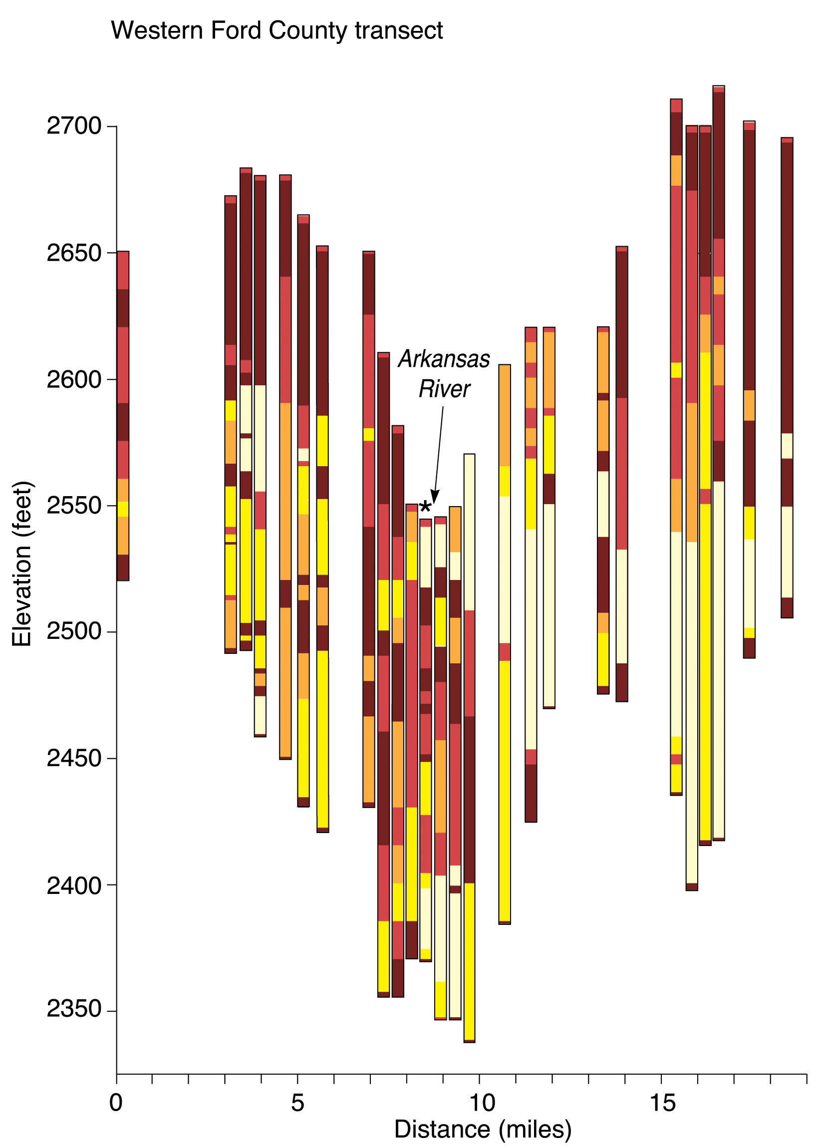
The Western Ford County section reflects the conceptual model of permeable alluvial and High Plains aquifers separated by a relatively impermeable layer of fine-grained material. The total thickness of unconsolidated deposits below the river valley is about 200 feet, which includes about 50 feet of basal sands and gravels filling a bedrock channel below the relatively thick impermeable layer. The alluvium is thin beneath the valley, but appears to thicken and connect with the High Plains aquifer to the south. Thick coarse-grained deposits are common south of the river, generally near the base of the High Plains aquifer, while fine-grained sediments appear to predominate just north of the river. A prominent bedrock ridge occurs approximately 5 miles south of the Arkansas River.
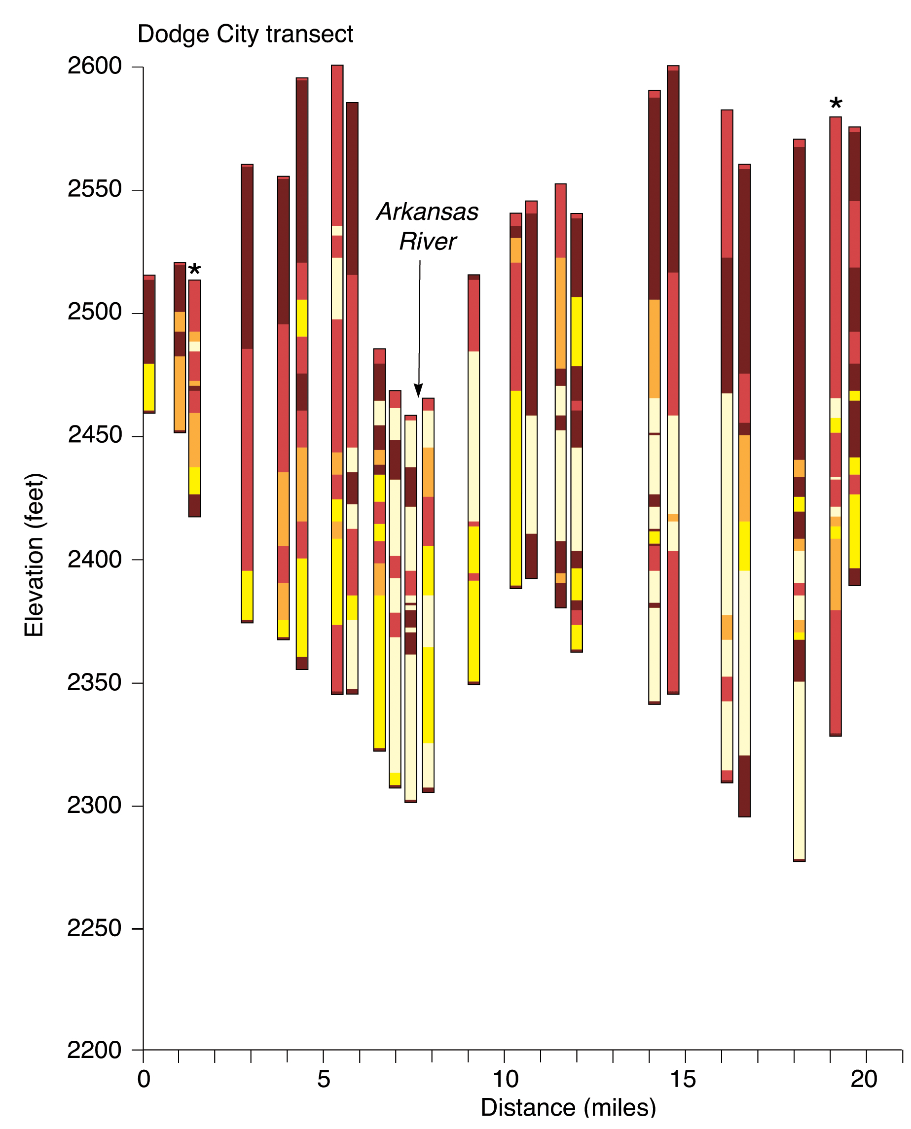
The total thickness of unconsolidated deposits below the river valley is only about 150 feet in the Dodge City section. The low-permeability layer underlying the alluvium is relatively thin. It appears that good hydraulic connection between the upper and lower aquifers occurs south of the river. Thick layers of sands and gravels appear continuous south of the river valley. Fine-grained sediments are more common to the north. Coarse-grained deposits are common at or near the base of the High Plains aquifer, especially south of the river. Similar to the Western Ford County section, basal sands and gravels fill a bedrock valley below the present Arkansas River valley. A prominent bedrock ridge is present a few miles south of the river. The bedrock surface rises abruptly at the southern extent of the section, as the Crooked Creek-Fowler fault is approached.
While the overall heterogeneity is evident in the north-south sections, some generalizations can be made. Fine-grained sediments tend to separate the shallow and deep aquifers north of the Arkansas River. Better hydraulic connection between the alluvial and High Plains aquifers is apparent south of the river. In many of the sections, clays appear very thin or completely absent a few miles south of the river, offering little or no separation between the shallow and deep aquifers. The thickest and generally the most permeable unconsolidated deposits occur south of the Arkansas River.
Dunlap, L. E., Lindgren, R. J., and Sauer, C. G., 1985. Geohydrology and model analysis of stream-aquifer system along the Arkansas River in Kearny and Finney Counties, southwestern Kansas: U.S. Geological Survey, Water-Supply Paper 2253, 52 p. [available online]
Gutentag, E. D., Lobmeyer, D. H., and McGovern, H. E., 1972a. Ground water in Kearny County, southwestern Kansas: U.S. Geological Survey, Hydrologic Investigations Atlas HA-416. [available online]
Gutentag, E. D., Lobmeyer, D. H., McGovern, H. E., and Long, W. A., 1972b. Ground water in Finney County, southwestern Kansas: U.S. Geological Survey, Hydrologic Investigations Atlas HA-442. [available online]
Gutentag, E. D., Lobmeyer, D. H., and Slagle, S. E., 1981. Geohydrology of southwestern Kansas: Kansas Geological Survey, Irrigation Series 7, 117 p. [available online]
Johnson, W. C., and Arbogast, A. F., 1993a. Geologic map of Finney County, Kansas (northern part): Kansas Geological Survey, Map Series M-28A. [available online]
Johnson, W. C., and Arbogast, A. F., 1993b. Geologic map of Finney County, Kansas (southern part): Kansas Geological Survey, Map Series M-28B. [available online]
Latta, B. F., 1944. Geology and ground-water resources of Finney and Gray counties, Kansas: Kansas Geological Survey, Bulletin 55, 272 p. [available online]
Lobmeyer, D. H., and Sauer, C. G., 1974. Water resources of Hamilton County, southwestern Kansas: U.S. Geological Survey, Hydrologic Investigations Atlas HA-516. [available online]
McGovern, H. E., and Long, W.A., 1974. Ground water in Gray County, southwestern Kansas: U.S. Geological Survey, Hydrologic Investigations Atlas HA-517. [available online]
McLaughlin, T. G., 1943. Geology and ground-water resources of Hamilton and Kearny counties, Kansas: Kansas Geological Survey, Bulletin 49, 220 p. [available online]
Meyer, W. R., Gutentag, E. D., and Lobmeyer, D. H., 1969. Finney County basic data: U.S. Geological Survey, Open-File Report, March 1969. [available online]
Meyer, W. R., Gutentag, E. D., and Lobmeyer, D. H., 1970. Geohydrology of Finney County, southwestern Kansas: U.S. Geological Survey, Water-Supply Paper 1891, 117 p. [available online]
O'Connor, H. G. and McClain, T. J., 1982. Ogallala aquifer study in Kansas--geohydrology: Kansas Water Office/Kansas Geological Survey 1982, 99 p.
Spinazola, J. M., and Dealy, M. T., 1983. Hydrology of the Ogallala aquifer in Ford County, southwestern Kansas: U.S. Geological Survey, Water-Resources Investigations Report 83-4226, 58 p. [available online]
Stullken, L. E., Watts, K. R., and Lindgren, R. J., 1985. Geohydrology of the High Plains aquifer, western Kansas: U. S. Geological Survey, Water-Resources Investigations Report 85-4198, 86 p. [available online]
Waite, H. A., 1942. Geology and ground-water resources of Ford County, Kansas: Kansas Geological Survey, Bulletin 43, 250 p. [available online]
Watts, K. R. and Stullken, L. E., 1985. Generalized configuration of the base of the High Plains aquifer in Kansas: U.S. Geological Survey, Open-File Report 81-344. [available online]
Whittemore, D. O., Tsou, M., and Grauer, J., 1996. Upper Arkansas River Corridor study: inventory of available data and development of conceptual models: Kansas Geological Survey, Open-File Report 96-19, 83 p.
Young, D., Grauer, J., and Whittemore, D., 1997. Upper Arkansas River Corridor Study: progress on lithologic characterization of unconsolidated deposits in the study area with emphasis on Kearny and Finney counties: Kansas Geological Survey, Open-File Report 97-43.
Kansas Geological Survey
Placed online December 18, 2007
Comments to webadmin@kgs.ku.edu
The URL for this page is http://www.kgs.ku.edu/Hydro/UARC/aquifers.html