Kansas Geological Survey, Open-file Report 2004-44
Part of the Direct Push Methods for Hydrostratigraphic Characterization Project
by
John M. Healey and Stephen M. Sellwood
Kansas Geological Survey
KGS Open File Report 2004-44
September 2004
A new exploratory tool for hydrogeological investigations of unconsolidated aquifers has been developed at the Kansas Geological Survey (KGS). The tool concept couples two invasive direct-push techniques into a single insertion-withdrawal operation by means of a dual rod arrangement. The Hydrostratigraphic Profiling Equipment (HyPT) combines the direct-push procedures of electrical conductivity profiling with temporary well installations. The Electrical Conductivity (EC) profile is first completed through the entire stratigraphic section (insertion). After the EC equipment is removed, a short well screen is placed into the formation for hydraulic testing. The screen can be repositioned numerous times within the aquifer, thereby developing a hydraulic conductivity profile of the formation (withdrawal). The configuration of the equipment and its one-borehole operation enables investigators to acquire detailed information concerning formation lithology and hydraulic conductivity. The evaluation and assessment of the equipment and the procedures consisted of ten profiling cycles conducted in a surface grid pattern at GEMS (KGS research site). The assemblage of equipment shows great potential as an investigation tool and with further development and testing may be used as a research tool for investigating ground-water chemistry. This profiling system was designed and engineered using equipment which is readily available and requires a minimal amount of modification. All modifications were completed at the KGS.
Small diameter wells are often used to characterize water chemistry, as well as to test for aquifer hydraulic parameters. Direct-push electrical conductivity profiles can be used to assess subsurface geologic conditions. A new and innovative exploratory tool has been developed at the Kansas Geological Survey (KGS) combining both tools into one device. "The Kansas Geological Survey Hydrostratigraphic Profiling Equipment (KGS HyPT)" is utilized for the characterization of subsurface hydrological and geological conditions within an unconsolidated alluvial aquifer. This tool arrangement is a product of advances made in direct push technology for site investigations. Direct-push technology is based on a principle of push and/or percussion drilling methods of driving various pieces of equipment and sensors into the substrata. This evolving technology led to the development of a variety of tools for site characterization as well as techniques and protocols for the installation of small temporary monitoring wells. Since the KGS HyPT is based on direct-push technology, its use is restricted to subsurface investigation of unconsolidated sediments.
At the KGS, subsurface investigations often begin with the completion of an Electrical Conductivity (EC) profile. The EC profile can be completed rapidly and is useful for defining the lithological variations within the substrata. A more complete description of this technique is given by Geoprobe Systems (1998). Stratigraphic thicknesses and gross lithologies shown on an EC profile provide information used for monitoring well installations. It is valuable in determining well specifications such as well-screen length, total depth of well, and grout intervals. The KGS approach joins the two stages of investigation and merges them into one expedient procedure. The HyPT tool combines the electrical conductivity profiling for lithological interpretation with temporary well installation for aquifer slug tests. Therefore, the equipment provides lithological and hydrological information in a single borehole.
The KGS HyPT was tested at the Geohydrologic Experimental and Monitoring Site (GEMS), a research site that lies within the floodplain of the Kansas River north of Lawrence, Kansas. The method used for this study is briefly described below. A complete description of the method, the field test, and the results are published in Sellwood et al., 2004, and Sellwood, 2001. The purpose of this paper is to describe the development of the equipment (KGS HyPT).
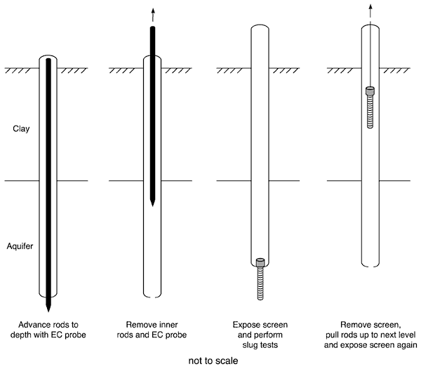
This method couples a dual rod approach for performing slug tests in direct push (DP) equipment with high-resolution EC logging. A schematic depicting the procedure is provided in Figure 1. Nested DP rods with an EC probe at the lower end of the inner rod string are first driven through the intervals of interest. The inner rods and the EC probe are then removed, leaving the outer rod string through which slug tests can be performed. After test intervals have been identified, based on the EC log or other considerations, the rods are retracted to the lowest interval to be tested. A screen is dropped to the bottom of the open rod string and held fixed while being exposed to the formation. The interval is developed and a series of slug tests is performed. The process is repeated at progressively shallower intervals to obtain a record of hydraulic conductivity (K) versus depth. Numerous profiles at a given site can be readily performed in this manner to determine the spatial variability of EC and K.
Figure 1. Diagram showing the hydrostratigraphic profiling procedure. (from Sellwood et al., 2004)
A series of profiles was performed at GEMS on a surface grid, resulting in a detailed depiction of the three-dimensional distribution of EC and K. Good agreement was found between K estimates obtained from this approach and those obtained using other methods (Sellwood et al, 2004). The results of the field evaluation indicate that direct push hydrostratigraphic profiling is a promising method for obtaining detailed information about spatial variations in subsurface properties without the need for permanent wells.
The equipment necessary to assemble the KGS HyPT can be divided into three categories based on the degree of modification. The categories are: off-the-shelf, modified off-the-shelf, and fabricated.
The KGS HyPT was designed and structured around readily available off the shelf components. The bulk of this category consists of drive rods and other associated equipment made available through Geoprobe Systems of Salina, Kansas. The major components include a set of inner 1-inch (outside dimension) O.D. and outer 2.125-inch O.D. rods. These rods are nested and driven simultaneously; therefore, it is imperative that the inner and outer rods are the same length. Only four-foot rods were used. Other smaller components of the KGS HyPT are 2.125-inch rod cutting shoe and 0.313-inch extension rods. Both the cutting shoe and the extension rods are available from Geoprobe Systems. Components of Geoprobe equipment were selected by choosing those requiring only slight modifications. The specific needs of the project were also a primary consideration. Several original pieces were designed and fabricated at the KGS. An off-the-shelf equipment list along with a brief description is provided below. Part numbers in the list refer to Geoprobe Systems, 1998. This project required 19 four-foot rod sections for a total (dual) rod string length of 76 feet.
| Off-the-Shelf Equipment Parts List: | ||
| Rods: | ||
| 19--1-inch O.D. x 4 ft. Part Number AT1048 | ||
| 19--2.125-inch O.D. x 4 ft. Part Number AT2148 | ||
| DT21 Cutting Shoe--Part Number DT4030 | ||
| Extension Rods: | ||
| 19--4 ft. Part Number AT671 with ends | ||
| Drive Cap for 2.125-inch rods--Part Number 8397 | ||
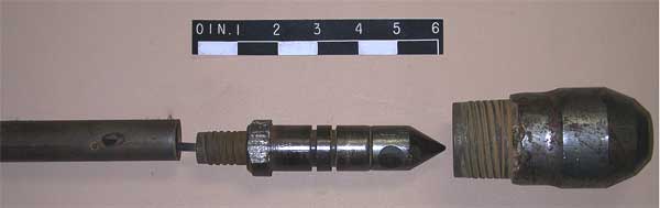
Two stock components of the system were available, although slight modifications were necessary. For this project, the Geoprobe Systems dipole electrical conductivity probe SC 300 was used. The dipole EC probe had an appropriate external dimension that allowed it to pass through the 2.125-inch cutting shoe of the outer rods. However, the probe's length was too short so an adaptor was required. For the adapter, we used a solid drive tip (Part No. DT4070). Coupling the dipole EC probe and the solid drive tip required several machining modifications. First, the dipole EC probe cable was cut midway between the probe tip and the connector. The dipole 1-inch rod thread end was machined to a 0.625-inch diameter and re-threaded with 0.625-inch X 28 NF threads.
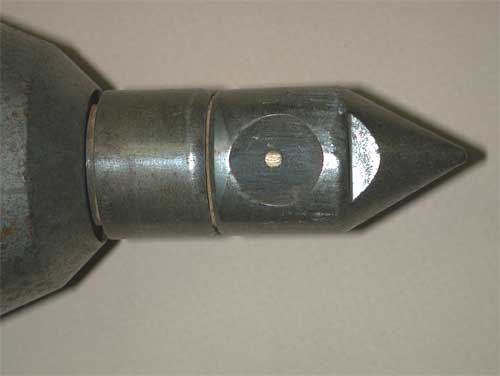
The next step required boring a hole through the solid drive point to accommodate the leads of the dipole, followed by removing the tapered point of the solid drive point and threading this end with internal threads: 0.625-inch X 28 NF (see Figure 2). The two components were assembled and test fitted into the 2.125-inch drive shoe. The landing shoulder of the solid drive tip did not allow the dipole probe to protrude far enough beyond the drive shoe so the shoulder was reduced by machining. This step also set the lower o-ring groove in the proper position as illustrated in figure 3, part a. The shoulder of the solid drive point is necessary to keep the nested rods together during field operation, therefore machining was kept to a minimum. The final assembly of the two parts was completed using a sealant and thread compound (see Figure 3, part b).
Figure 2. (a) Photo of the Geoprobe components prior to machining. (b) Scale diagram illustrates the coupling of the SC 300 dipole electrical conductivity probe to 1-inch solid drive point.
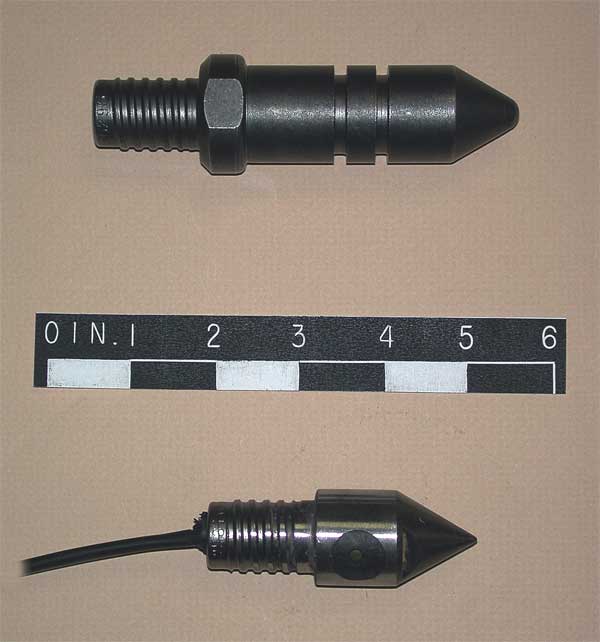
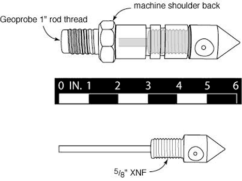
Figure 3. Electrical Conductivity Dipole Assembly. (a) EC probe seated in cutting shoe. (b) Exploded view (left to right): 1-inch inner drive rod, EC dipole probe coupled to modified 1-inch solid drive tip and outer 2.125-inch outer rod cutting shoe.
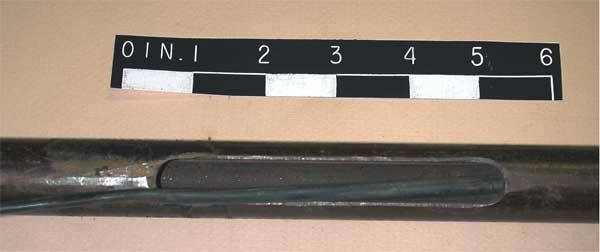
The first 1-inch rod connected to the probe and solid drive tip assembly required minor modification. A weep hole was drilled into the first 1-inch rod near the probe end to allow for drainage during disassembly. A large slot was milled up the rod to allow the EC cable to exit the 1-inch rods and track upwards in the annular space of the nested rods (Figure 4).
| Modified Off the Shelf Equipment Parts List: | ||
| Conductivity Dipole Probe--Part Number SC300 | ||
| DT21 Solid Drive Tip--Part Number DT4070 | ||
Figure 4. Photo of 1-inch rod with machined slot to accommodate EC cable (Seis cord). Marks Products Seis Cord--100 ft. of two conductor electrical cable
Two drive caps were necessary to use the KGS HyPT. Drive caps were manufactured from solid round steel. A slotted drive cap was fabricated to drive the 2.125-inch rods and the smaller inner rods at the same time (Figure 5). The inner dimensions of the cap were designed to slide over the threads of the 2.125-inch outer rods and then rest on the rod shoulder for solid driving. In addition, this large drive cap was bored to accept the drive cap of the inner set of 1-inch rods.
Figure 5. (a) Photo of fabricated drive caps. (b) Scale diagram of fabricated drive caps.
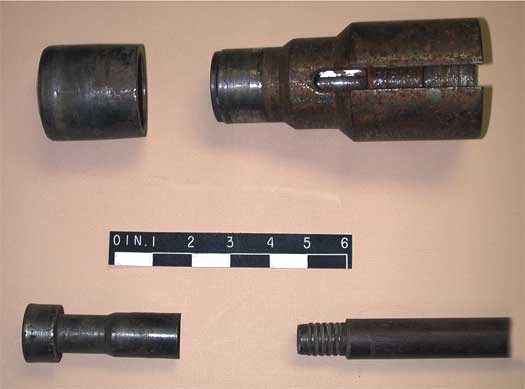
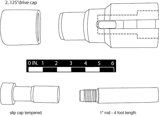
The slot in the large drive cap allowed the EC cord to exit from the annular space between the two sets of rods to be connected to the EC collection equipment. Surface hardening was completed over the entire surface of the cap; however, this treatment was inferior. Therefore, the top of this fabricated part was machined to accommodate a 2.125-inch standard drive cap (Part No. 8397) to reduce the risk of damage to the hammer of the probe, 2.125-inch rod joints, or the fabricated 2.125-inch slotted drive cap.
The smaller drive cap was designed to slide over the threads and rest on the shoulder of the inner 1-inch rods. The top of the cap fit inside the large drive cap so that both rod sets were simultaneously advanced. The profile relief was machined into the smaller cap to keep the EC wire from being severed during hammering and driving. This part was also heat-treated to extend its life and protect other components.
As mentioned earlier, the SC300 probe wires were cut midway between its connector and the probe tip. Several different types of probe conductor wire were tested with this equipment. A two-conductor seismic cable proved to be the most durable.
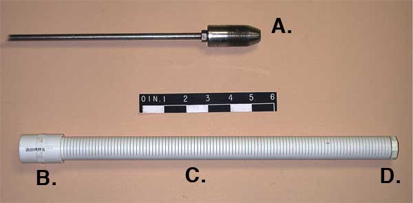
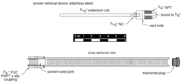
Hydraulic conductivity profiling of unconsolidated formation with the KGS HyPT required the repetitive removal of the screen. For this procedure, the KGS developed the screen retrieval system. It is simplistic in design and very easy to fabricate. As shown in the following diagram (Figure 6), component A is a tapered tool attached to 0.313-inch extension rods. This is the most important feature of the retrieval system. This component is constructed from 1-inch stainless steel round stock. The machined threads are the same as the screen, i.e. 0.75-inch NPT. Approximately 3 inches in length, the tool is tapered so it follows into the threaded portion of the screen as it is lowered into the 2.125-inch outer string of rods. Clockwise rotation of the tool from the surface screws it into the top of the screen. When resistance to rotation is met, the tool is securely attached to the screen and is hoisted to the surface for cleaning or replacement. This procedure is termed "fishing the screen." This extraction tool is vented to the specifications in the following diagram. This venting of the screen drains water as it is hoisted to the surface and minimizes formation heave.
Figure 6. (a) Photograph showing screen retrieval tool and screen components. Parts consist of: A. 3/4-inch MNPT x 5/16-inch NC attached to rod screen retrieval tool; B. solvent weld 1-inch PVC coupling x 3/4-inch FNPT; C. 1-inch diameter PVC screen--14 inches in length x 10 slots; D. 1-inch PVC screen plug. (b) Cross section of screen retrieval tool and screen components.
The KGS Hydrostratigraphic Profiling Tool (KGS HyPT) was developed in conjunction with a method for using the equipment. The equipment and the method were tested during a field study at the GEMS research site. The results of the field study indicated that the equipment could be reliably used to obtain detailed information about the electrical and hydraulic conductivity of an unconsolidated aquifer (Sellwood et al., 2004, and Sellwood, 2001). Good agreement was found between electrical conductivity and hydraulic conductivity values obtained with the KGS HyPT and with other conventional methods used at the research site.
Geoprobe Systems. 1998. Tools and Equipment Catalog. Salina, Kansas.
Sellwood, S.M. 2001. A direct-push method of hydrostratigraphic characterization. M.S. thesis, Department of Geology, University of Kansas, Lawrence.
Sellwood, S.M., J.M. Healey, S. Birk, and J.J. Butler Jr. 2005. Direct-push hydrostratigraphic Profiling: Coupling Electrical Logging and Slug Tests: Ground Water, v. 43, no. 1, 19-29. [PDF online]
Kansas Geological Survey, Geohydrology
Placed online Jan. 9, 2006
Comments to webadmin@kgs.ku.edu
The URL for this page is http://www.kgs.ku.edu/Hydro/Publications/2004/OFR04_44/index.html