| Original published in W.W. Hambleton, ed., 1959, Symposium on Geophysics in Kansas: Kansas Geological Survey, Bulletin 137, pp. 181-197 | ||
Engineering Geology Branch, U.S. Bureau of Reclamation
The complete article is available as an Acrobat PDF file.
Results of geophysical investigations by the United States Bureau of Reclamation in Kansas over a period of 16 years are summarized. Refraction seismograph and electrical-resistivity methods were used to study possible damsites and to determine quantity of materials available for construction purposes. Reconnaissance refraction surveys to determine bedrock depth at Elkader, Elkader Alternate, and Pyramid damsites on Smoky Hill River in Gove and Logan Counties indicated, based on bedrock depth only, that Elkader was the most desirable site because bedrock was at minimum depth. Resistivity investigations at the Herndon and Ludell quarry sites in Rawlins County were made to locate zones of opaline-cemented material in the Ogallala formation for use as riprap. Because these zones had a higher resistivity than surrounding material, it was possible to supplement drill-hole information for yardage computations. Similar investigations were made at a quarry in Ness County near Cedar Bluff damsite. Estimates of available material were in close agreement with independent estimates made by engineers. Seismic refraction studies at Cedar Bluff damsite on Smoky Hill River in Trego County located and traced a known buried stream channel and showed that it did not have an outlet along the toe of the dam and thus could not provide a leakage path for water in the reservoir. A similar investigation at the site of Kirwin Dam in Phillips County on North Fork Solomon River was used to outline and trace the course of two buried channels that cut the axis of the proposed dam. Reconnaissance refraction seismograph studies were made at the site of the proposed Glen Elder Dam on North Fork Solomon River in Mitchell County to supply subsurface information for selection of the best site. Depth determinations were in close agreement with drill-hole depths used as control points.
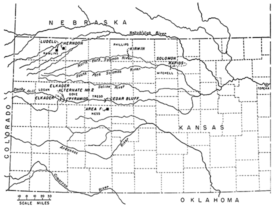
During the last 16 years geophysical investigations were made at six different projects of the United States Bureau of Reclamation in Kansas (Fig. 1). For each project these investigations solved, or helped to solve, problems confronting Bureau geologists and engineers in the examination and selection of damsites or in other phases of their work.
Figure 1--Location map of Kansas showing sites of United States Bureau of Reclamation geophysical investigations.
Geophysical field studies at reclamation projects are of a type that may be classified as shallow geophysical prospecting. For example, the objective of a survey may be to find the depth to bed rock at a dam site or the yardage of gravel in a deposit. This is in contrast to the usual (deep) geophysical prospecting for oil-bearing structures, which has been carried on so successfully in Kansas since about 1927.
The examples that follow show how needed subsurface information was obtained at sites of Bureau engineering structures by geophysical means. Because few examples of such work have been published, these may be useful to others engaged in the planning and construction of major engineering projects such as dams, canal systems, and highways.
The first geophysical work of the Bureau of Reclamation in Kansas was done by John Baird, Staff Geophysicist, in November 1941. He made reconnaissance seismic surveys of three alternate damsites on Smoky Hill River, in Gove and Logan Counties, in the western part of the state.
The first site investigated was at the town of Elkader on U.S. Highway 83 and was known as the Elkader Damsite. The second site, a few miles down stream to the east, was called the Elkader Alternate No. 2 Damsite. The third site, 7 1/2 miles down stream from Elkader, was named the Pyramids Damsite. These sites are shown in Figure 1.
The three sites are in an area typical of the uplands of western Kansas. Smoky Hill River, which has its origin in eastern Colorado and flows eastward into Kansas, has cut a valley more than a mile wide through Tertiary cover down to the Niobrara chalk formation, of Cretaceous age.
The overburden ranges from sandy loam at higher altitudes, along the proposed axes of the dams, to sand and gravel in the river bottoms. The stream itself is wide and slow moving, an indication of old age and channel aggradation. The bed of the river ranges from 150 to 200 feet in width. The Niobrara formation, which is the bedrock at the sites studied, consists of massive chalk and alternating shaly chalk beds.The objective of the geophysical investigation was to obtain a detailed bedrock profile on the axes at the three damsites. These profiles would provide a basis of comparison so that the most favorable site could be selected. The seismic refraction method was used to determine depths to bedrock at points on the proposed dam axis.
Elkader Damsite--The bedrock depth at this site as determined by the seismic refraction method is shown on the profile in Figure 2A. From the profile, surface elevations and bedrock depths may be determined for points along the proposed axis.
Figure 2--Profiles showing depth to bedrock as determined by seismic refraction method at proposed damsites. A, Elkader Dam axis. B, Elkader Alternate No. 2 Dam axis. C, Pyramids Dam axis.
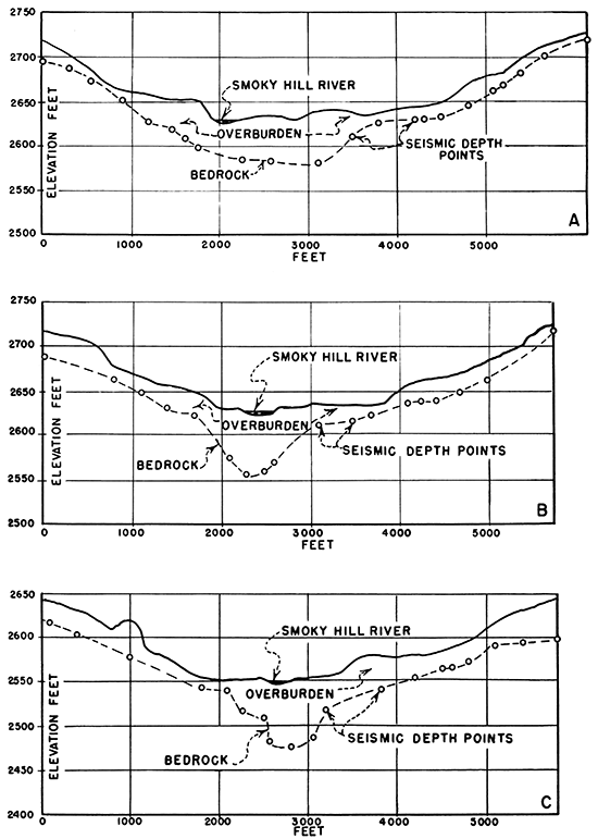
The depth points plotted along the bedrock line were geophysically determined, as noted, and the "rock line" was drawn between them. The profile shows that bedrock near the abutments was covered by a relatively thin overburden, which became thicker in the river valley bottom. The maximum depth of 60 feet was measured at a point 3,100 feet from the left abutment, or on the left side of the river looking down stream. Along the profile across the valley the depth ranged from 35 to 60 feet.
Elkader Alternate No. 2 Damsite--The bedrock profile along the proposed axis at this site is shown in Figure 2B. The overburden thickness is somewhat greater than at the Elkader site and ranges from 57 to 70 feet. Comparison of Figures 2A and 2B shows that conditions at the abutments of the two damsites are very similar.
Pyramids Damsite--The geophysical results at this site are shown in Figure 2C, which brings out that the average depth to bedrock is considerably greater than at the Elkader site. The maximum depth found was 72 feet, but the overburden on the abutments at the Pyramids site is 10 feet thicker than at the Elkader sites. This feature is the most important difference between the sites.
Differences in the depth to bedrock as derived from the seismic geophysical survey are the only basis for comparison of the three sites. The Elkader site would be the most desirable, because bedrock was at minimum depth. The seismic determinations of bedrock depth were of a reconnaissance character as no drilling had been done at any of the sites.
The second geophysical investigation by the Bureau of Reclamation in Kansas was under the direction of the writer, in May and June 1948. It consisted of electrical-resistivity field measurements at the Herndon and the Ludell rock quarries in Rawlins County, in the northwest part of the state. These quarries are named for the towns of Herndon and Ludell respectively, near which they are located, as shown in Figure 1.
The plains area, including western Kansas, generally is lacking in adequate supplies of hard rock for construction and other uses. Silicified zones and lenses in the Ogallala formation, of Pliocene age, are, however, one source of hard rock in the region (Frye and Swineford, 1946). The Ogallala lies at the surface over much of the area and consists mainly of calcareous grit, sandy clay, and sand; there is a basal conglomerate in many places. Zones of sandstone and conglomerate silicified with opaline cement, which are called quartzite, occur mainly near the base of the formation in certain localities.
These bodies of quartzite range from a few feet to 1,000 feet or more in extent and from 1 foot to 15 feet in thickness. Their variability and lenticular shape make them difficult to outline by drilling.
The geophysical field work at these quarry areas, along with drilling, was done to locate an adequate supply of rock, suitable for riprap, for the Bonny Dam at Hale, Colorado, and other major dams in the general area. At the time this work was done (June 1948) it had not been determined from what source the riprap for the Bonny Dam could be obtained most economically. Bonny Dam, one of the major dams of the Missouri River Basin Project, is about 125 miles west of Ludell.
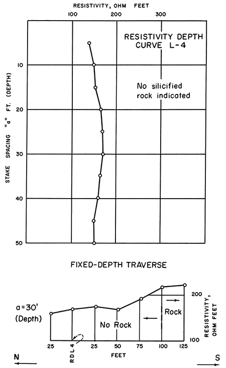
The electrical-resistivity method, using a Wenner configuration, was employed to locate and outline bodies of silicified rock. The basis for its use in this investigation is that the quartzite has a resistivity 3 to 5 times greater than the material above or below it. Figures 3 and 4 illustrate this point.
Figure 3--Resistivity depth curve L-7 and graph of fixed-depth traverse at Ludell quarry area, Rawlins County, Kansas.
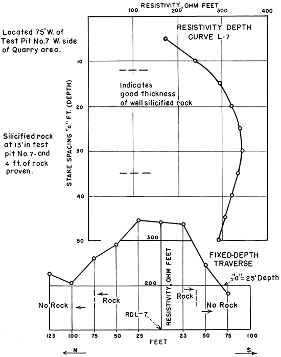
Figure 4--Resistivity depth curve L-4 and graph of fixed-depth traverse at Ludell quarry area, Rawlins County, Kansas.
Specifically, the objectives of the geophysical work were:
Herndon Quarry--In 14 days of field work, 29 resistivity depth measurements and 2,200 feet of fixed-depth resistivity traverse were completed. One unit of resistivity field equipment was used for the entire time and a second unit for about 50 percent of the time. The resistivity operations were coordinated with the drilling and reduced the number of necessary drill holes.
At the end of the 2-week period noted, it was estimated that 197,000 cubic yards of silicified rock could be obtained at the Herndon deposit. This estimate was based on field observation of outcrops, information from more than 40 core-drill holes and 36 jackhammer holes, as well as the resistivity measurements.
This yardage of rock was overlain by a maximum of 30 feet of overburden; rock under more than 30 feet of overburden was not included in yardage computations. Seemingly, about 3 yards of overlying material would have to be removed for each yard of riprap obtained.
A revised figure on the yardage of rock at the Herndon site was made after an additional week of field investigation from June 6 to 11. It was then estimated that only 195,300 cubic yards of riprap rock had been developed. This slight decrease in yardage was due to the fact that, upon further investigation, the amount of rock in one part of the quarry did not come up to expectations. The revised figure was in close agreement with the amount calculated independently by the Bureau of Reclamation Materials Engineer concerned with the investigation.
The quartzite at the Herndon Quarry is somewhat variable as to fineness of grain and degree of silicification and hardness. In some places it is found in layers 1 foot or more in thickness, which are separated by a few inches to 2 feet of unconsolidated sandy material. In other places a solid core of silicified rock 9 feet in length was obtained, and no sandy zones are present.
Ludell Quarry--The Ludell rock deposit is located about 10 miles west of Herndon. In 3 days of field work, 9 resistivity depth measurements and about 825 feet of fixed-depth traverse were completed. This work supplied information on the silicified rock layer that tied in with information from trenching and test pits.
The resistivity work indicated that a somewhat greater area was underlain by rock that could be quarried than had been estimated previously. Prior to this investigation about 39,000 yards of silicified rock had been outlined at the Ludell Quarry. The quartzite is of better quality and more nearly uniform than that at Herndon.
Part of one day was spent examining an outcrop that represented the most westerly exposure of the Ludell rock deposit, and one resistivity depth measurement was made. It was found that the silicified rock extended less than 75 feet back from the exposed face. The locality at the western edge of the deposit was therefore eliminated from further consideration.
At the Herndon Quarry, estimates showed nearly 200,000 cubic yards of silicified quartzite rock in place. At the Ludell Quarry about 39,000 yards of similar rock was available and geophysical work indicated even more yardage was present there.
Resistivity depth measurements and fixed-depth resistivity traverses eliminated the necessity for drilling some holes, strengthened and supplemented the drill information, and speeded the investigation, resulting in a decrease in overall cost.
Field resistivity measurements reported above, and earlier field work on a quartzite deposit near Akron, Colorado, suggest that the resistivity of the quartzite is directly proportional to its soundness; the higher the measured resistivity the harder and more silicified the rock.
Field investigations by the electrical resistivity method were made at "Quarry Area F", 17 miles south of Ellis, Kansas. This quarry area is in Ness County about 15 miles southeast of the Cedar Bluff damsite, as shown in Figure 1. The purpose of the geophysical work at the Area F Quarry was to supplement earlier core drilling so that the yardage of silicified rock in the deposit could be more accurately estimated. The field equipment and procedures used at the Herndon and Ludell rock deposits, previously described, were employed at the Area F Quarry. The problem was similar in both places.
The resistivity field work was planned in consultation with the engineers of the Cedar Bluff Dam who were concerned with the quarry investigations. Two sets of resistivity apparatus were used, each of which was operated by a crew of four men. Two of these men had worked on earlier quarry investigations, hence very little time was required to establish efficient field operations.
Resistivity work began July 7, 1948, and was completed July 15, 1948. In seven working days 30 resistivity depth measurements and 1,600 feet of fixed-depth traverse were completed. This exploration supplemented 42 core holes in the quarry area, which was about 3,800 feet long by 750 feet wide.
Resistivity depth determinations were first made at certain drill holes and also near outcrops to establish the values of resistivity of the overburden and of the quartzite as criteria for interpreting subsequent measurements. On July 15, the writer estimated that 189,000 cubic yards of silicified rock was available at the Area F Quarry. At the request of the Project Construction Engineer this estimate was made independently and without knowledge of other calculations of the amount of rock in the quarry. It proved to be in close agreement with estimates prepared in the Project Office.
The Area F deposit was favorable for quarry operations. The quartzite was at or near the surface; the average thickness of overburden was approximately 5 feet. In the estimate of yardage the only rock included was that which extended back from the outcrop to a point where there was a maximum of 15 feet of overburden.
Resistivity measurements supplied the information necessary for a revised estimate of the yardage of rock in the quarry area at less cost and in less time than would have been required to perform additional core drilling for this purpose.
The Cedar Bluff Dam on Smoky Hill River is located approximately 18 miles southwest of Ellis, Kansas, in Trego County. This dam was the first major feature of the Missouri River Basin Project to be completed by the Bureau of Reclamation in Kansas.
Smoky Hill River, which flows eastward, has cut to a depth of about 300 feet at the damsite. The exposed section consists of surface alluvium, dune sand, and terrace deposits of Quaternary age. Below these deposits are 'flat-lying Ogallala limestone and sandstone of Tertiary age. Cretaceous Fort Hays chalk and Carlisle shale underlie the Ogallala formation. The shale is the bedrock at the damsite, where the river valley is about 6 miles wide.
Core drilling at the damsite developed evidence of a so-called preglacial buried channel. This channel was about 1,000 feet wide and 60 feet deep where it crossed the proposed axis of the dam on the left abutment side. Bedrock in the channel was approximately 110 feet from the surface. These features are shown in Figure 5.
Figure 5--Map showing location of buried channel and section through buried channel at Cedar Bluff Dam site, Trego County, Kansas.
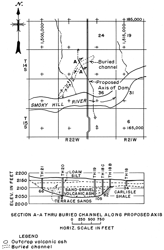
Examination of drill logs and the results of pumping tests indicated that the channel was filled with pervious material containing volcanic ash, sand and gravel, and some clay. It was realized that the buried channel, after crossing the axis from the west (or upstream direction) might turn south and follow along the downstream toe of the proposed dam, thus creating an undesirable condition.
The purpose of the investigation was to trace by seismic refraction method the course of the ancient buried channel. Seismic field work at the Cedar Bluff Dam site began September 15 and ended October 6, 1948. During this period of 13 days a total of 20 seismic "spreads" or exploration lines and about 90 bedrock depth measurements were completed. An area approximately 3,500 feet long by 2,500 feet wide was covered in sufficient detail that the bedrock and the buried channel could be shown by subsurface contours.
The depth to bedrock as determined from existing core holes was used as control for the interpretation of the seismic measurements. Where seismic depth points were near these drill holes, it was found that, in almost all cases, the calculated seismic depth to the shale checked the depth obtained from drilling within about 5 percent.
As the investigation progressed, it became apparent that the old channel was simply an erosional feature on the bedrock, or buried drainage. Its course was southwestward to the point where it crossed the dam axis and drained into the reservoir area behind the dam. The seismic studies indicated definitely that the buried channel did not have an outlet near the downstream toe of the dam.
The seismic investigations were carried out by a crew of 7 men. The elevations and locations of the geophones, or seismic wave receivers, and the "shot points" where explosive charges were detonated, were established by an instrument man and a rodman. The seismic instruments and field truck were operated by R. H. Kuemmich, Electronics Technician with the Engineering Laboratories Division, Office of the Assistant Commissioner and Chief Engineer, Denver, Colorado, and three helpers supplied by the Project. The operation was supervised by the writer, who studied the seismic records and made the depth calculations. It was estimated that a seismic depth point cost approximately $30.
The results of the exploration were assembled on a map showing the shale bedrock surface of the area at a 10-foot contour interval. This map is comparable to a topographic map in the degree of detail shown. This comparison suggests that, with some drill-hole control, the seismic refraction method can provide information on the configuration of bedrock at damsites. Thus, the proposed axes of dams can be located in relation to bedrock topography in much the same manner as they are fitted to surface topography.
The course of the buried channel that cut across the proposed axis of the Cedar Bluff Dam, on the left abutment, was mapped by the seismic-refraction method. By seismic studies it was found that this channel would not provide a leakage path for water in the reservoir and that it did not have an outlet along the toe of the dam. Exploration was completed in 13 days at less cost and more quickly than would have been possible by drilling. About 90 bedrock depth points were measured at an estimated cost of $30 per point.
A seismic field investigation by the refraction method was made at the site of the Kirwin Dam, in Phillips County, Kansas. This dam is on North Fork Solomon River near the town of Kirwin (Fig. 1).
Two buried channels in bedrock were discovered during the initial drilling at the site. One channel was on the left abutment and the other on the right abutment of the proposed dam.
The bedrock at the abutments of the dam is the Fort Hays chalk member of the Niobrara formation. Bedrock in the valley section of the dam is the Carlisle shale, which lies below the Fort Hays chalk. Both of these formations are of Cretaceous age. The overburden in the area consists of reworked chalk covered by a thin layer of silt, sand, and loess.
The purpose of the seismic investigations was to outline and trace the courses of these buried channels for the guidance of pre-construction drilling. Field operations were carried out by Robert D. Casey, Geophysicist with the Bureau of Reclamation at that time, and the writer with the assistance of personnel assigned by the Project Office. Mr. Hugo Hernandez, geologist from Venezuela, who was an official visitor at the Bureau, participated in the work. Seismic field operations were carried out during a 4-week period in January and February 1952.
The work was done in the same general manner as in the other seismic investigations described. The first seismic lines were at and near drill holes so that a correlation could be established between the seismically determined depth to bedrock and the depth found by the drill.
The seismic records obtained at the Kirwin Dam site were of good quality; i.e., the seismic energy from the shot came in strongly at each geophone and produced a record that was easy to analyze. There was good contrast between the seismic velocity in the weathered overburden and in the firm chalk or shale bedrock. Specifically, the wave velocity in the overburden, or loess layer, was about 1,000 feet per second. The velocity in the second layer, consisting of sandy material and reworked chalk, was approximately 2,000 feet per second. The third layer, made up of Fort Hays chalk or Carlisle shale, had a velocity of approximately 7,000 feet per second.
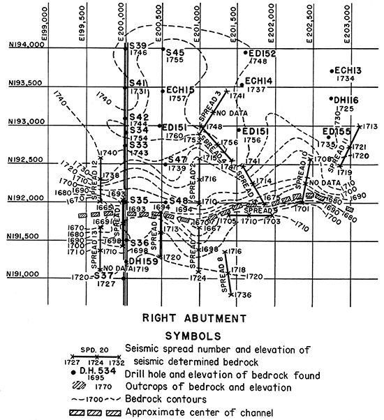
The buried bedrock channel that cut the proposed dam axis on the right abutment side was mapped in detail through 36 seismic depth points and several drill holes. Bedrock contours were carried east of the dam axis for a distance of 3,500 feet. A study of the surface geology, in an area beyond that surveyed with the seismograph, indicates that the downstream course of the channel leads back into the present river bed. These features are shown in Figure 6, which reveals also that the width of the channel on bedrock ranges from 150 to 500 feet.
Figure 6--Map showing bedrock contours as determined by seismic refraction method at Kirwin Dam site, Phillips County, Kansas.
The buried bedrock channel cutting through the left abutment of the Kirwin Dam was traced through 84 seismic depth points and drilling, for about 3,000 feet. The bottom of the channel was on the Carlisle shale.
The investigation at the Kirwin Dam was similar to that at the Cedar Bluff Dam in that buried channels that cut across the axis of the proposed dams were traced and mapped. These examples demonstrate that where such buried channels are known at one or more points, because of drilling, they can be followed and outlined geophysically more quickly and at less expense than by drilling alone.
Upon the completion of the seismic work at the Kirwin Dam site, a brief reconnaissance seismic investigation was undertaken to supply subsurface information for selection of the best axis for the proposed Glen Elder Dam at the Solomon Rapids site on North Fork Solomon River about 6 miles downstream from the town of Glen Elder, in Mitchell County, Kansas (Fig. 1).
The Solomon Rapids site is about 60 miles downstream from Kirwin, and because conditions are very similar at these two places, they will not be discussed further.
The field work was performed by Geophysicist Robert D. Casey and Geologist Cleland N. Conwell, who were attached to the Geophysics Section of the Bureau of Reclamation. They were assisted by Project personnel. The investigation required only 7 days, from February 13 through February 20, 1952.
The subsurface profile on top of the bedrock, presumably Carlisle shale, was determined for (1) an east-west line along Highway 24, 1f2 mile north of Solomon Rapids Post Office, and (2) the east-west section-line road 1 mile north of Highway 24. Both of these lines were approximately 2 miles long. They were selected because they were accessible and would cross two of several considered dam axes.
Preliminary drilling provided control for the seismic depth determinations. The first shot point of the first spread was located near a drill hole. The depth to bedrock as determined seismically was 26 feet; the drill-hole log indicated a depth of 25 feet. At a second control point, the seismic depth determination was 69 feet as compared with a drill depth of 64 feet. Comparisons at other control points also indicated good correlation between seismic and drill depths to bedrock.
As a result of the seismic work, in which 15 spreads were completed and which supplied 48 depth determinations, the following interpretation of subsurface conditions was made:
These findings influenced and provided a starting point for subsequent exploration in the area.
The examples discussed cover studies made in Kansas. They are typical examples of some of the ways in which geophysical methods are used by the Bureau of Reclamation in engineering geologic investigations.
Frye, J. C., and Swineford, Ada (1946) Silicified rock in the Ogallala formation: Kansas Geol. Survey Bull. 64, pt. 2, p. 33-76. [available online]
Kansas Geological Survey
Comments to webadmin@kgs.ku.edu
Web version Dec. 1, 2013. Original publication date 1959.
URL=http://www.kgs.ku.edu/Publications/Bulletins/137/Wantland/index.html