|
|
|
|
Photos from June 2003 |
|
|
|||
| Click on a photo to view larger version | |||
|---|---|---|---|
 |
 |
 |
 |
 |
 |
 |
 |
 |
 |
||
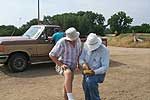
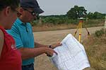
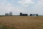
| To establish an absolute location for the seismic grid that will be deployed twelve times over the next six years and to try to make contact with several of the key farmers and operators, a group from the KGS spent a half day at the field site on June 18, 2003. The group included: Brett Bennett, David Laflen, Jamie Lambrecht, Rick Miller, and Theresa Rademacker. The primary objective of this trip was to establish an absolute location for the injector well and to try to avoid the roads and major obstacles with geophone stations.
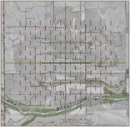
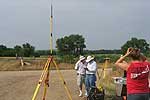
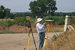
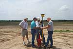
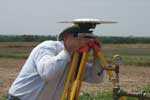
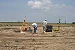
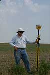
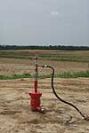
The high resolution Trimble DGPS (differential global position system) owned by the KGS was set up at the intersection of the county roads in the southeast corner of the receiver grid (Figure 1). The system includes a base (4800) and rover (4700) that are radio linked together (Figure 2930). When an appropriate number of satellites are available the system can measure x, y, and z to sub-inch accuracy. Once the systems have been linked and sufficient satellite coverage established, the hand-held computer provides real-time readouts and logs all pertinent information (Figure 2927). Pre-survey layouts of the grid were updated and a new grid calculated that better fit the terrain and cultural features (Figure 2935). Analog maps were used to keep track of affected landowners and farmers and to provide an overview of general station locations. Once all the obstacles were identified and receivers were optimally placed within the study area, the system was recalibrated and a new grid was calculated (Figure 2931). By moving the rover around the study area, obstacles were located that could interfere with line deployments (Figure 2936). A semi-permanent marker was installed at the base of the CO2 injector (Figure 2940). On June 18 the CO2 injector well pictured here was injecting fresh water at a sustained pressure of 500 lbs. With the help of Kevin from Muffin Drilling a marker location was established that will be our primary absolute reference and will be undisturbed for the duration of the project (Figure 2942). To establish the location of this permanent base, the base GPS unit was set up over the marker, located less than a foot from the base of the CO2 injection well (Figure 2946). The base and rover units were set up at the injector well site, satellite contact established, and x, y, z measured to an accuracy of less than an inch (Figure 2647). When the center of the entire seismic grid was located at the CO2 injector well, one of the five receiver lines went directly through the center of the tank battery and pump shed (Figure 2949). The grid center was moved about 30 ft north to avoid the tanks. Farmers and landowners that have been contacted to date have been extremely helpful and more than willing to work with us however they could. On-site discussions with Don Mai, Wayne Funk, and Roy Rein were very promising and their agreement to cooperate with us is and will be critical to the success of this project. Figure 1. Base map of site with roads. The red dots are sources, the green dots are P-wave receivers, and the yellow are S-wave receivers. The larger green dots are where both P- and S-wave receivers overlap. The GPS base station is near the intersection of the yellow lines. A larger version of this figure is available.
|
|||
|
Kansas Geological Survey, 4-D Seismic Monitoring of CO2 Injection Project Placed online June 30, 2003 Comments to webadmin@kgs.ku.edu The URL is HTTP://www.kgs.ku.edu/Geophysics/4Dseismic/Photos/jun03.html |