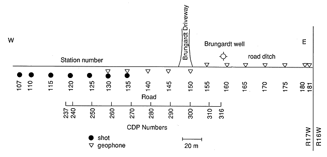
Kansas Geological Survey, Open-File Rept. 90-27
Annual Report, FY89--Appendix C
Use "Back" on your browser to return to the page you were viewing.
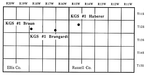
One channel sandstone has already been mapped using available well logs in western Russell and eastern Ellis counties.. Three test holes drilled by the KGS served as control points to test the accuracy of the seismic methods used in this study. Synthetic seismograms were used to tie the well-log information to the seismic sections and to aid in the interpretation of the reflecting events.
Four lines were shot at locations that had different near-surface conditions and were at different levels within the stratigraphic column. Interpretation of each of the lines compared to to the test-hole data and evaluation of data quality formed the basis for evaluating the feasibility of using seismic reflection methods for providing reliable information on the subsurface sedimentary architecture and the geometry of the sandstone lenses.
Figure C.1. Location of the study area and testholes drilled by the Kansas Geological Survey.
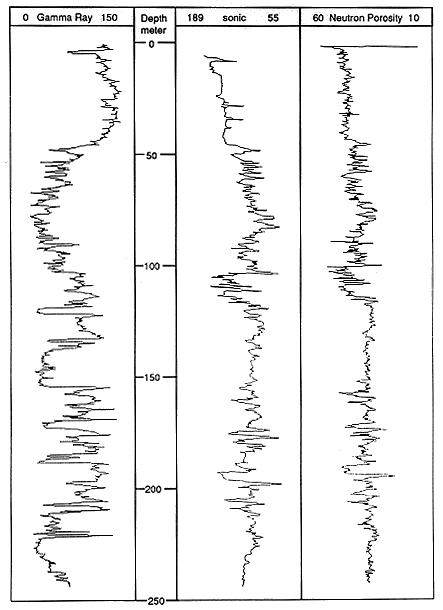
The Permian Stone Corral Formation is the lowest stratigraphic unit of interest in this study (Figure C.2). Depth to the Stone Corral Formation is approximately 675 ft. and 1270 ft. at the Haberer and Brungardt test holes, respectively. The thickness of the Stone Corral Formation is approximately 40 ft. throughout the area. In the subsurface, the Stone Corral Formation consists largely of white to light-gray crystalline anhydrite, commonly referred to as the Cimarron anhydrite. The wide distribution, distinctive lithology, and relatively young age of the Stone Corral Formation have made it a key marker bed in western Kansas. In addition to being easily recognizable on well logs, the Stone Corral Formation produces strong reflections on seismograms (Merriam, 1955).
Figure C.2. Generalized stratigraphy in the study area.
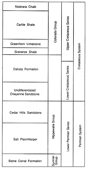
The Harper-Salt Plain Formations and the Cedar Hills Sandstone (Permian) of the Nippewalla Group are generally recognized as the only Paleozoic formations above the Stone Corral in the study area. The Harper-Salt Plain Formations are composed chiefly of red silty shale (Zeller, 1968) and the combined thickness is approximately 300 ft. thick in the study area. Above the Salt Plain is the Cedar Hills Sandstone near the top of the Permian. Red silty to sandy shales and siltstones, and sandstone are the principal lithologies represented in the Cedar Sandstone. The thickness of the Cedar Hills ranges from zero in the eastern part of the study area to more than 150 ft. in the western part due to pre-Cretaceous erosion of the Permian in the study area.
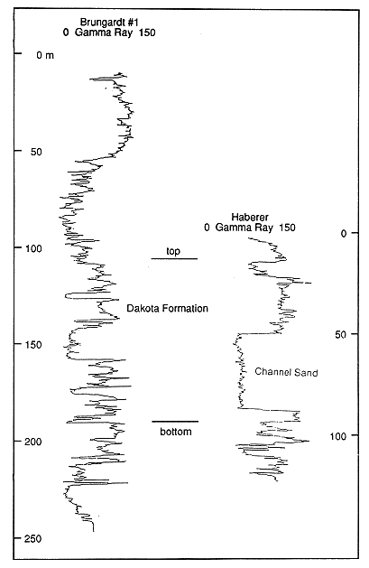
Above the Cretaceous-Permian unconformity, the undifferentiated Kiowa-Cheyenne and Dakota Formation are present in the study area. The lower part of the Dakota Formation is characterized by floodplain overbank deposits of mottled light-gray and red kaolinitic clay and thick, multi-storied lenses of channel sandstone. One such channel has been mapped in western Russell and eastern Ellis counties (Figure C.3). The channel sand is 135 ft. thick and lies at a depth of 168 ft. in the #1 Haberer (Figure C.4). It is absent in the Brungardt well but there are several thin sands (3 to 10 ft. thick) at the same stratigraphic position. A sand body 53 ft. thick is present at a stratigraphic position higher than the channel sand. The total thickness of the Dakota Formation is 277 ft. in both wells.
Figure C.3. Isopach map of the channel sandstone at the base of the Dakota Formation.
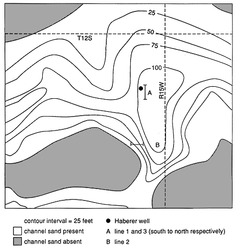
Figure C.4. Correlation of the two test wells.
The Graneros Shale conformably overlies the Dakota Formation and records the eastward transgression of the shallow Western Interior Sea during the Greenhorn cyclothem. The predominant lithology of the Graneros is noncalcareous silty shale (Hattin, 1965). In the Haberer well the Graneros Shale is 20 ft. thick and is overlain by 10 ft. of Pleistocene alluvium. In the Brungardt well, the Graneros is 38 ft. thick.
The Greenhorn Limestone consists of thin-bedded chalky limestone and calcareous shale Greenhorn sediments are not penetrated by the #1 Haberer, which is located just below the Greenhorn Limestone outcrop. In the #1 Brungardt, this formation is 90 ft thick.
The Carlile Shale overlies the Greenhorn Limestone and is subdivided into two members. The KGS #1 Brungardt penetrated approximately 200 ft of this formation (19-215 ft). The Blue Hill Shale Member is the uppermost member of the Carlile Shale below the surface and consists of clayey, noncalcareous shale. The underlying Fairport Chalk Member is a chalky shale that contains stringers of limestone (Merriam, 1963). Above the Carlile Shale there are approximately 19 ft. of Quaternary unconsolidated terrace deposits at this site.
Structure
The Central Kansas uplift is the most prominent structural feature in the study area. It is a northwest-trending structural high that separates the Hugoton embayment to the west from the Salina and Sedgwick basins to the east (Merriam, 1963). A regional structure map contoured on the top of the Stone Corral Formation shows the pre-Desmoinian, post-Mississippian structure as a broad, northwest-sloping surface with no regional arching (Merriam, 1963). The structural dip of the Stone Corral Formation in the vicinity of the Haberer well is less than 5 ft./mile. The Stone Corral Formation can be considered a flat lying datum on the scale of this study.
Spatial or lateral resolution refers to how close two reflecting events can be situated horizontally, yet be recognized as two separate points rather than one (Yilmaz, 1987). The limit of spatial resolution is determined by the width of the first Fresnel zone. A decrease in wavelength or the related increase in frequency will decrease the radius of the Fresnel zone and increase the spatial resolution of the data.
Obtaining high resolution data from the shallow subsurface was the goal of this study. Source, receivers, and line parameters were all chosen to increase the frequency of the data recorded. The data recorded had dominant frequencies ranging from 95 Hz to 200 Hz. With an average formation velocity of 8250 ft/s, the vertical resolution ranged from 21.8 to 10.2 ft. Resolution of the data to these limits depended heavily on the amount of noise present on the seismic record. The spatial resolution ranged from 56 to 82 ft at a depth of 165 ft and from 162 to 234 ft. at a depth of 1270 ft. These are the depths from the top of the channel sand in the Haberer well and the top of the Stone Corral Formation at the Brundgardt well, respectively.
Figure C.5. To operate, two graduate students stand on the base plate and fire the rifle.
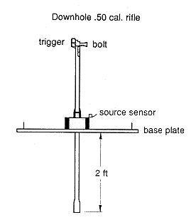
A downhole .50 caliber rifle (Figure C.5) was used as an energy source to collect low-cost shallow seismic reflection data. The downhole rifle was used because it has a higher frequency source pulse and an increased signal-to-noise ratio compared to the silenced surface .50 caliber rifle used in previous work (Steeples et al., 1987). One 750-grain bullet was fired at each shot location. A hole approximately 3 ft deep was drilled at each shot location previous to using the downhole rifle. A Giddings auger towed by a field vehicle was used to drill shot holes. It worked well when shot holes were located on roads or in level fields. Shot holes were also drilled using power auger manufactured by Pro-TechTM mounted on a Yamaha all-terrain vehicle.
The seismic recording truck is equipped with an Input/Output DHR 2400 seismograph. It is a 24-channel fixed-gain system with an 11-bit analog-to-digital (A/D) converter plus 1 sign bit. Modules having switch selectable 55-110-220 Hz and 110-220-340 Hz low-cut filters were used in the DHR 2400 during recording. The filters have 24-dB/octave rolloff below their corner frequencies. The 220-Hz low-cut filter reduces the amplitude of 110-Hz energy by 24 dB and 55-Hz energy by 48 dB before A/D conversion. Lowcut filters were used before A/D conversion to cut down the magnitude of low-frequency components. This allowed a significant number of bits to be filled with high-frequency signal (Knapp and Steeples, 1986). High-cut filters were used to reduce the amplitude of unwanted high-frequency noise and to prevent aliasing of high frequencies. The seismograph has 3000-Hz (-60 dB point) anti-alias filters that are always in use. Analog gains were used to amplify the seismic signal close to but not greater than the maximum voltage accepted by the A/D converter.
Receiver groups were composed of two series-connected 100-Hz geophones on line 1 and three series-connected 40-Hz geophones on lines 2, 3, and 4. High-frequency geophones acted as an additional low-cut filter because they had a -6-dB/octave response to frequencies below their resonant frequency (Knapp and Steeples, 1986). The series-connected geophones were planted in short arrays either in line, to help cancel the air-coupled wave generated by the source, or perpendicular to the line, to cancel wind noise. Aside from cancelling horizontally traveling noise, series-connected geophones added vertically arriving signals in phase.
Walkaway Noise Test
Acquisition parameters chosen for a shallow seismic survey control the quality, resolution, and ability to record reflections from a particular horizon. The optimum window technique has been used successfully to record shallow reflectors from bedrock using common offset techniques (Hunter et. al., 1984). At the KGS, similar techniques combined with common depth point (CDP) acquisition and processing have provided a technique to gather reflection information for a variety of shallow engineering, structural, groundwater, and environmental projects (Steeples and Miller, 1988; Myers et al., 1987; Treadway et al., 1987). Before going in the field, simple modeling of the expected target is used to help select acquisition parameters. Once in the field, a walkaway test is used to check and improve the selection of parameters (Knapp and Steeples, 1986).
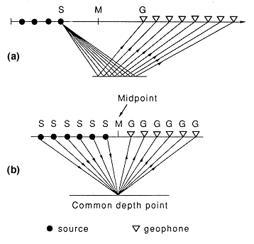
Walkaway noise tests were used to determine acquisition parameters at each of the sites in this study. The procedure was as follows: Forty-eight or more closely spaced receiver locations were laid out with the geophones in each group planted next to each other (bunched). The source was placed at one receiver location spacing from the end of the line then moved away from the line. Shots were taken at increased intervals, providing a continuous record of seismic response at changing source-receiver offsets. Filter and gain settings were adjusted with each shot. Field plots of each of the seismic records were then analyzed to determine receiver spacing, shot spacing, source to near receiver offset, maximum receiver offset, high-cut and low-cut filters, notch filter, gains, and sample interval for each of the four lines collected for this study . All the lines were shot using end-on spread geometry (Figure C.6).
Figure C.6. (a) All the data was shot using end-on geometry. (b) Data was then sorted into CDP gathers during processing.
Topography
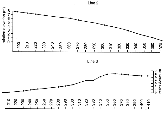
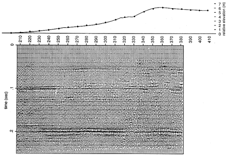
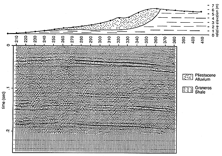
During data acquisition, it is necessary to accurately describe the line geometry and any deviations from that geometry. Any changes in the position of the receiver or of the shot locations from the normal geometry can be accounted for during processing. One important change along the line that needs to be described is elevation. An elevation change at the surface might be interpreted as dip on the reflector if it was erroneously assumed that the surface was flat. A hand-level and stadia rod were used to measure relative elevation changes every fifth station along line 2 and line 3 (Figure C.7). Line 1 and Line 4 were relatively flat and elevations were not measured.
Figure C.7. Relative elevation on lines 2 and 3.
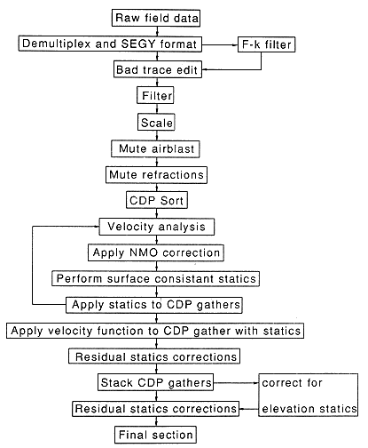
The goals of processing were to improve the signal-to-noise (S/N) ratio of the data and to display the data as stacked CDP seismic sections convenient for geologic interpretation. The amount of signal recorded in the field cannot be increased by data processing. Processing is used to remove, or at least suppress, noise. In this way, the S/N ratio can be increased and reflections can be more easily identified. The general processing flow used is shown on Table C.1. For a general explanation of these processes, see Yilmaz (1987). Static corrections and F-K filtering are discussed further.
Table C.1. General processing flow.
Static Corrections
If the near-surface material on each line has a constant seismic velocity, then the calculation of the elevation static correction is trivial. All that is required is to simply add or subtract the amount of time required for the seismic energy to travel the vertical distance between a reference elevation and the elevation measured (Dobrin, 1976). Velocity variations in the near surface, however, vary laterally along the lines, with depth, and with elevation. These variations make static corrections for elevation difficult. Minor variations in travel times associated with minor depth changes of the near surface and with small elevation differences can be accounted for using AUTS, an automatic statics process available in SPEX, which computes a series of surface-consistent statics. This process cannot correct for changes in elevation across the whole line. At this point the data can be interpreted so long as the change in elevation is taken into account (Figure C.8). For this study a correction for topography was not necessary to interpret the data. However, the Stone Corral Formation was be used to make elevation corrections by picking a reference time closest to a control point. The amount of time shift necessary to move the Stone Corral reflection to the reference time was measured off the final stacked section. The time shifts were applied using the Statics Application card (STAT) available in SPEX. After the shift was applied, residual statics were applied to correct for minor errors in the time shift calculation (Figure C.9).
Figure C.8. Reflectors dip to the north due to the change in topography. A larger version of this figure is available.
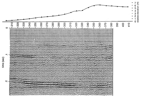
Figure C.9. Elevation static corrections are applied that flatten the Stone Corral reflection at 2 seconds. A larger version of this figure is available.
F-K Filtering
One of the problems with shallow reflection seismology is coherent linear noise (air-coupled waves, ground roll, refractions, and direct arrivals), which obscures reflection information arriving at the same time. Frequency filtering can be used to suppress noise when the noise and signal have different frequencies. The noise and signal, however, often have similar frequencies and cannot be discriminated by frequency filtering. This is when F-K filtering is extremely useful.
Dipping events in the time-space (t-x) plane can be separated by their dips in the frequency-wavenumber (f-k) plane. In f-k space, the coherent linear noise can be isolated from reflection energy and then eliminated (Yilmaz, 1987). A two-dimensional Fourier transform is used to transform the data from (t-x) space to (f-k) space (Figure C.10). Conventional implementation of the Fourier transform can lead to wraparound noise. Extension of the data beyond the ranges of the spatial and temporal axes, by padding with zeros, can help to avoid this problem. Increasing the size of the array increases the time and cost of the operation (Yilmaz, 1987).
Figure C.10. F-K filter was applied twice. Once to remove linear noise at 1250 m/s and then to remove noise at 1350 m/s.
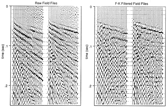
To help eliminate the coherent linear noise seen on line 1 an f-k filtering program was used. The f-k filter was designed to remove energy with a particular velocity. Linear moveout was applied to the data in t-x space at the velocity to be removed. After the data was transformed into f-k space, the unwanted linear noise was aligned vertically along the frequency axis with a wavenumber of zero. The wraparound also lined up on the axis, eliminating the need for excessive padding with zeros. A fan cut filter, centered at a wavenumber of 0, was then applied. The input into the program was the file name, trace spacing and the width of the fan filter. The velocity to be removed was the center of the fan chosen. Because the tapering was very smooth, a wide fan was used. A test of the filter on field files from line 2 shows that it removed linear noise (Figure C.11). One important advantage of using linear moveout before applying the two-dimensional Fourier transformation and extremely gentle tapering is that artifacts that might be misinterpreted as true reflections were not created.
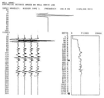
The synthetic seismograms used in this study were created using the Snark module in TERRALOG (Doveton and Cable, 1986). Figure C.11 shows the output of the TERRALOG program. Synthetic seismic traces were calculated using a 100-Hz Ricker wavelet and the sonic log from the Brungardt test hole. The amplitude values created from the program were saved in a disk file using the file command in TERRALOG. Then, using the program TERRATOKGS.PR the synthetic traces were converted to SPEX format. This allowed the synthetic traces to be scaled and plotted using the SPEX package.
Figure C.11. Terralog output using the sonic log from the Brungardt well and a 100 Hz Ricker wavelet.
Each type of log was plotted against the sonic log to determine whether there were any relationships (Figure C.12). The plot of the neutron porosity values against the sonic values shows a well-defined linear relationship. The gamma ray and litho-density values do not show a direct relationship to sonic values. When the velocity log and the neutron porosity log are plotted together, the correlation between the porosity values and the sonic values is obvious (Figure C.13). The neutron porosity tool measures the amount of hydrogen in a formation. Water, whether in the pore space, bound in clays, or in a crystalline structure such as gypsum, is the primary source of hydrogen being measured. The relationship between the sonic log and porosity log indicates that, as water content increases, velocity decreases. The shales in the interval of interest are only moderately compacted, as seen by their high water content. Although the neutron porosity (NPOR) log showed the greatest correlation with the sonic log (DT), both the gamma ray (GR) and litho-density (DEN) logs were used to predict sonic values in the Haberer well. Other researchers in Kansas have noted the relationship between neutron porosity values and sonic values and used this information to make pseudo-sonic logs from neutron porosity logs when sonic logs were not available (Ready, 1985; Seeber, 1985). The predictive value of the neutron porosity log is fortunate because neutron porosity logs are commonly run in Kansas wells. In this case the neutron porosity log alone was sufficient to make a pseudo-sonic log but all the information was used because it was readily available.
Figure C.12. The neutron porosity log shows a linear trend with the sonic log.
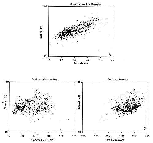
Figure C.13. Comparison of sonic log and neutron porosity log, Brungardt #1 well. The sonic log and neutron porosity logs show stong correlation.
The following equation was solved for coefficients A, B, C, and D using linear regression on the logs from the #1 Brungardt:
DT = A + (B x GR) + (C x DEN) + (D x NPOR).
The regression was made using values from a depth of 150 to 800 ft . The values for coefficients are given in table below.
Table C.2. Regression coefficients.
| Depth Interval | A | B | C | D |
|---|---|---|---|---|
| 150-800 ft | 77.183 | 0.029 | -7.425 | 1.689 |
| 350-650 ft | 69.167 | -0.045 | -4.304 | 1.859 |
A comparison of the synthetic seismic trace made from the sonic log and one made from a pseudo-sonic log using the coefficients found using a linear regression equation shows good correlation (Figure C.14). The interval used to calculate the coefficients included the Greenhorn Limestone, which consists mostly of limestone and chalky shale (Merriam, 1963). The Haberer well, where the pseudo-sonic log is needed, does not go through the Greenhorn Limestone. It begins in Pleistocene alluvium just above the Graneros Shale. The Graneros Shale, the Dakota Formation, and the Kiowa Shale are the only units logged in the Haberer well. A second set of coefficients was calculated using the interval from 350 to 650 ft in the Brungardt well, which correlates to the interval penetrated by the Haberer well. The synthetic seismic traces made from the Haberer well logs uses the second set of coefficients in Table C.2.
Figure C.14. Comparison of synthetic seismograms made from the sonic log in the Brungardt well and pseudo-sonic logs calculated from other well logs. A) pseudo-sonic calculated from density and neutron porosity logs. B) sonic logs. C) pseudo-sonic calculated from gamma-ray, density, and neutron porosity logs.
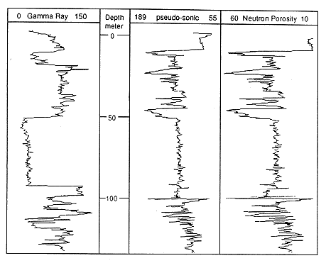
The pseudo-sonic log calculated for the Haberer well is shown in Figure C.15, together with the gamma ray log and the neutron porosity log. The strong influence of the neutron porosity log in creating the pseudo-sonic log is obvious. The target sandstone at the base of the Dakota Formation was friable and porous. The normal increase in velocity expected in going from shale to sandstone was evidently enhanced by the high water content and porosity of the shales.
Figure C.15. Comparison of pseudo-sonic log and neutron porosity log, Haberer Well. The pseudo-sonic log predicts acoustic impedence contrasts at the top and bottom of the channel sand.
The frequency of the first-order Ricker wavelet used in making the synthetic seismic trace varies depending on the dominant frequency of the reflecting events on the each of the seismic sections. A 95-Hz wavelet was used for line 1. Line 3 had much higher frequencies and a 200-Hz wavelet was used to make the synthetic seismogram. Line 4 had reflection information right at 100-Hz within the interval that was logged. A 100-Hz wavelet was used for the synthetic seismogram on line 4.
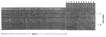
Walkaway 1 was shot next to the site of the Haberer well (Figure C.4). In this test the geophones were planted in the ditch next to the road and the shot holes were drilled on the road. The Graneros Shale was at the surface in the ditch. Open, 110-Hz, 220-Hz, and 340-Hz low-cut filters were tested (Figures C.16 and C.17). Source-receiver offsets were tested from 4 ft to 388 ft. The data show reflection information exceeding 170-Hz above 0.150 sec (Figure C.17). Reflections above 130-Hz were recorded from the Stone Corral Formation at a depth of approximately 710 ft. The results of this first test indicate that the channel sand could be visible with reflection seismology at this site.
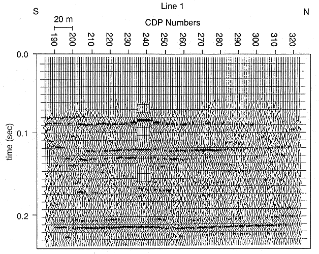
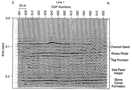
Line 1 was shot 330 ft south of walkaway 1 in the Saline River Valley on August 24, 1988. Pleistocene terrace deposits are at the surface where this test was conducted. The site was chosen because it was relatively flat and elevation measurements were not needed. The receiver spacing was 8.2 ft and the offset from the source to the nearest receiver was 49.5 ft. The offset from the source to the far receiver was 235 ft. Two 100-Hz geophones were spaced inline 1.5 ft apart to help cancel the air-coupled wave from the source. The offset window is shown in Figure C.17. Starting at the south end of the line, shot holes were drilled in the ditch adjacent to the road. Shot holes drilled from the middle of the line to the north end of the line had to be drilled in the road because the truck could not drive any further in the ditch.
The frequency of the data was lower than anticipated. The reflection at 0.12 sec is only 90-Hz (Figure C.18). On the walkaway shot a week earlier, reflections with frequencies of 170-Hz were seen at times greater than 0.12 sec. Also, the data quality was worse on the north end of the line. The drop in data quality coincided with a change in the position of the source from in the ditch to on the road.
Figure C.16. Walkaway tests next to the Haberer well. A larger version of this figure is available.
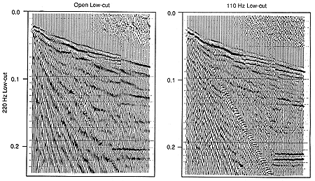
Figure C.17. High-frequency reflections are identifiable on the walkway shot with 340 Hz low-cut filters. A larger version of this figure is available.
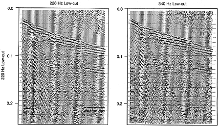
Figure C.18. Reflections on line 1 have dominant frequencies between 90 and 100 Hz.
The reflector at 0.12 sec is interpreted as the base of the channel sand. The sands below the channel cannot be separated from the reflection at the base of the channel. The top of the channel is visible at 0.085 sec. The synthetic seismogram created using information from the Haberer well shows that at a frequency of 90 Hz, the series of acoustic impedance contrasts associated with sands directly below the channel sand cannot be resolved (Figure C.19). The synthetic seismogram matches the field data and supports the interpretation. The reflector at 0.21 sec is the Stone Corral Formation. The reflection at 0.16 sec is from impedance contrasts within the upper part of the Permian section.
Figure C.19. Interpretation of line 1. The synthetic seismogram supports the interpretation. A larger version of this figure is available.
Drought conditions had existed all summer in the study area and the alluvium was very dry. The near-surface conditions, dry unconsolidated alluvium, on which the line 1 was shot was the variable that changed from the shooting of the walkaways a week earlier. The drop in the dominant frequency is most likely associated with the attenuation of energy in the dry, unconsolidated sediments. Variation in the thickness of the alluvium caused static problems on the CDP gathers. The reflection from the Stone Corral Formation was used to monitor static corrections applied to the data during processing. Better data quality would be expected if the drought conditions had not existed and the water table had been close to the surface in the alluvial valley. Lower attenuation of high frequency energy and better source coupling have been noted in areas where the near surface is saturated (Hunter et al., 1984; Rick Miller, personal communication 1989).
The thickness of the channel sand was reduced in 5 ft. intervals in the pseudo-sonic log and synthetic seismic traces were made at each interval. The series of synthetic traces were plotted together to model a hypothetical pinchout of the channel sandstone. The model shows the pinchout as a thinning of the transparent zone between the reflection at the top of the channel and the reflection from the Kiowa Formation (Figure C.20).
Figure C.20. A pinchout of the channel sand could be recognized as a thinning of the transparent zone. A larger version of this figure is available.
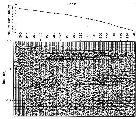
Line 2 Walkaway 2 was shot in an east-west direction along the county road down the middle of Sec. 26, T. 12 S., R. 15 W. The site, 2 mi. south of the Haberer well, was picked because the isopach map of the channel sand predicts that the sandstone thins by 50 to 83 ft. (Figure C.3). The site is also higher in the stratigraphic section than the site for line 1. The Greenhorn Limestone is at the surface. Bad weather conditions contributed to the low signal-to-noise ratios seen in the data. Source-receiver offsets were tested from 10 to 356 ft. The field plots of the walkaway tests did not show any reflection information. Refractions, ground roll, air-coupled wave, and "ringing refractions" are the only coherent events that can be recognized on the walkaways (Figure C.21). The high level of noise is especially apparent on the far offsets.
Figure C.21. Reflections are not apparent with all the linear coherent noise and environmental noise. A larger version of this figure is available.

Parameters were chosen despite the lack of reflection information, and the line was shot hoping that processing could bring out reflections not seen on the field plots.
Stacked refractions on the final section of line 2 show the effect of the change in topography (Figure C.22). As the elevation decreases, the travel time from the surface to the refractor decreases and the stacked refraction events appear higher on the section. This influence is also seen on the Stone Corral reflection at 0.24 sec on the east end of the line. At the west end of the line, the Stone Corral reflection barely appears on the record, but as the elevation decreases by 26 ft, the reflection becomes more apparent on the east end of the line. There are several poor coherent events between CDP 270 and CDP 310 from 0.1 sec to 0.2 sec. that may have been more readily interpreted had the amount of random noise been less.
Figure C.22. Reflections are not apparent on the CDP section of line 2. A larger version of this figure is available.
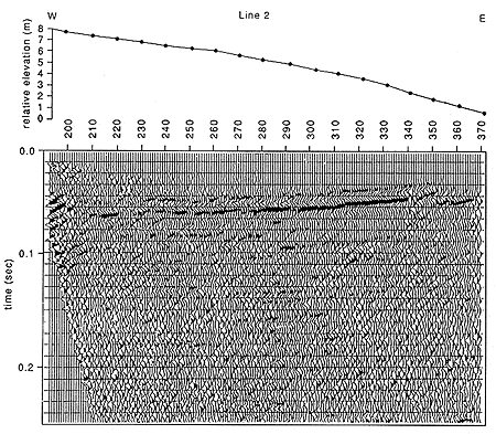
The stacked section of line 2 indicates that the walkaway tests were reliable. Processing did not bring out any significant reflection information. Coherent linear noise seen on the walkaways previously seem to be masking reflection information expected at the same arrival times. F-k filtering was used to remove linear noise with velocities of 4125 and 5049 ft/s. After filtering, the same processing steps were applied to the f-k filtered field files. The final section of the f-k filtered data looks a little less noisy than the previous section (Figure C.23). The f-k section does not reveal any reflections not seen on the band pass filtered section. A comparison of field files before and after F-K filtering showed that the filter had removed linear noise at the filtered velocities (Figure C.11). The lack of coherent reflection events from file to file after F-K filtering indicates that A/D conversion had been saturated with coherent and random noise. Reflection information was not recorded above this high level of noise. The 12-bit A/D converter did not have enough dynamic range to record the signal under such noisy conditions.
Figure C.23. F-K filtering did not substantially improve the reflection information. A larger version of this figure is available.
Line 3
This line is located at the site of walkaway 1 where the Graneros Shale is at the surface. A new walkaway test was set up with both geophones and shot holes located in the ditch on the west side of the road. The results showed that 200-Hz reflection information could be recorded within the window of interest (Figure C.24). The parameters for line 3 were then chosen. The receiver and shot spacing were set at 6.6 ft. Three 40-Hz geophones were planted in line in a 2 ft array to help cancel out the air wave from the source. The minimum and maximum source-to-receiver offsets were 40 and 191 ft., respectively. The optimum window selected is shown on Figure C.22. 220 Hz low-cut and 1000-Hz high-cut filters were used in this section.
Figure C.24. Reflections from both the top and bottom of the channel sand are apparent on the walkaway. A larger version of this figure is available.
The top of the channel sand can be seen at approximately 0.06 sec. on Line 3 (Figure C.25). The base of the channel is seen at 0.09 sec. The reflection at the base of the channel is 200 Hz on the south end of the line. Several reflections can be seen below the Dakota Formation on the south end of the line. As you move north on the line, the frequency and data quality drop. At CDP 233 the frequency drops on the reflection at the base of the channel sand. At CDP 255 data quality drops on the reflection at the base of the channel sand. The changes coincide with a gradual change in topography and surface conditions (Figure C.26). The severe drop in data quality between CDP 320 and CDP 350 is due to an increase in the thickness of alluvium and bad surface plants. A cement pad and two shallow shot holes lowered the number of shots taken through this area lowering the fold as well. Geophones were planted in fresh exposures of the Graneros Shale on the south end of the line. Pleistocene alluvium deposited unconformably on the Graneros Shale gradually increases in thickness to the north. Just over the crest seen on the topographic profile the Graneros is again at the surface, coinciding with an increase in data quality at the north end of the line.
Figure C.25. The channel sand is readily apparent at the top of the CDP section. A larger version of this figure is available.
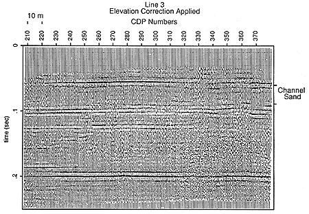
Figure C.26. Changes in reflection quality can be associated with changes in near-surface geology. A larger version of this figure is available.
The reflections from other sandstones observed below the channel sand on well logs from the Haberer well are visible. The reflections between 0.1 sec and 0.12 sec are from the Kiowa Shale. The reflection at 0.12 sec is interpreted as the contact between the Kiowa Shale and the Cedar Hills Sandstone. The reflection at 0.19 sec. is the Stone Corral Formation. A synthetic seismogram made using a 200-Hz wavelet shows that the base of the channel sand and sandstones within the Kiowa Formation can be resolved. The synthetic seismogram matches the field data and supports the above interpretation (Figure C.27).
Figure C.27. Interpretion of line 3. The synthetic seismogram supports the interpretation. A larger version of this figure is available.

The high frequency data of line 3 not only allows easy interpretation of the channel sand in question, but also the contacts between the Dakota Formation, Kiowa shales and sandstones, and the underling Permian beds can be resolved. A continuation of line 3 to the north would most likely be capable of resolving the pinchout of the channel sand and changes in the relationships between Lower Cretaceous rocks and the underlying Permian rocks.
Line 4
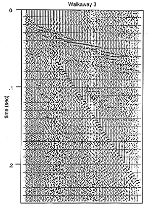
Line 4 was located at the Brungardt test-hole site. Stations were flagged in an east-west direction 10 m south of the Brungardt well. Three 40-Hz geophones were planted at each station. Spacing on the walkaway was 6.6 ft. The walkaway tested source-receiver offsets from 6.6 ft to 686 ft. Times after the arrival of the air blast were saturated with low-frequency ground roll on the walkaway shot with open low-cut filters (Figure C.28). Low-cut filters were set at 110 Hz, and high-cut filters were set at 250 Hz. Noise from a front-end loader working at the east end of the line can be seen on the walkaway (Figure C.29). Acquisition of data must stop and wait for such disturbances to end. Reflections are visible on the far offsets. The sampling rate was changed to 0.5 msec so that reflections from the Stone Corral Formation could be recorded. The system is limited to 1000 samples per trace which would give 0.25 sec of data at 0.25 msec sampling and 0.50 sec of data at 0.50 msec sampling. At this site the Stone Corral reflection was at 0.33 sec.
Figure C.28. Low frequency ground roll at the Brungardt site. A larger version of this figure is available.
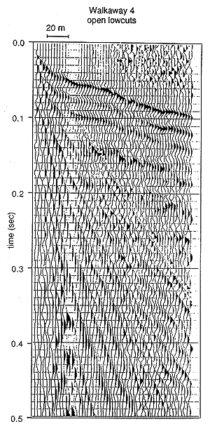
Figure C.29. Walkaway test from the Brungardt site. Large offsets were used to get reflection information. A larger version of this figure is available.
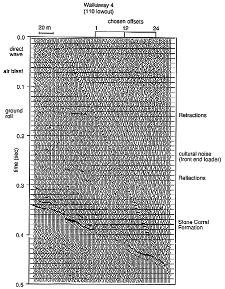
The near source-to-receiver offset was set at 304 ft and the far source-to-receiver offset was set at 607 ft. These offsets are shown on Figure C.30. Receiver and shot locations were placed every 13 ft. The low-cut and high-cut filters were set at 110 Hz and 220 Hz, respectively. Sampling rate remained at 0.5 msec. Total record length was 0.5 second.
Figure C.30. Geophones planted in the road ditch are associated with higher frequency and better quality reflections on the CDP-stacked section.
Eighty-two stations were flagged. Shot holes were drilled from station 107 to station 135. Receivers were located from station 130 to station 181. Receivers were planted on the edge of the road from station 130 to station 152. Receivers located at stations 153 and higher were planted in the road ditch on the side of the road (Figure C.30). All the shot holes were drilled in the road.
Because of the large source-receiver offsets, the first reflections are seen at 0.10 sec (Figure C.31). A zone of several broken up reflectors runs from 0.10 sec to 0.20 sec. A more coherent reflector can be seen at 0.21 sec. The most coherent reflectors are at 0.26 sec and 0.33 sec. Reflections from Cretaceous formations (0.10 to 0.25 sec) are not as coherent as deeper reflections from the Nippewalla Group and from the Stone Corral Formation. The reflection from the Stone Corral Formation increases in data quality and frequency from CDP 243 to CDP 273. The changes coincide with changes in the surface where the geophones are planted. The more CDP receivers planted in the road ditch rather than on the road, the better the reflection (Figure C.30).
Figure C.31. Frequency of the reflection at .33 s increases to the east. A larger version of this figure is available.
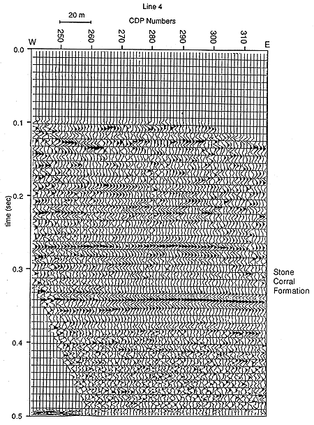
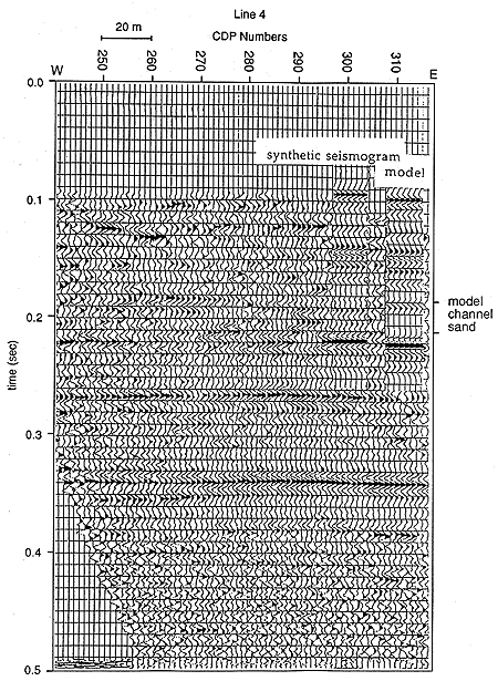
At this location the channel sand is not present. The base of the Dakota Formation is at a depth of 620 ft. A sand only 15 ft. thick is at the base. There are several sands within the Dakota Formation ranging from 3.3 to 53 ft. in thickness (Figure C.4). The reflections on line 4 have a dominant frequency of 100 Hz. The thin sand lenses at the base of the Dakota Formation can not be resolved with 100 Hz wavelets. The contact between the base of the Dakota Formation and the underlying Kiowa Shale has a sharp change in velocity shown on the sonic log from the Brungardt well and has definite kick on the synthetic seismogram made from the sonic log (Figure C.12). The synthetic seismogram was converted to SPEX format and spliced into line 4 (Figure C.32). With the aid of the synthetic seismogram the base of the Dakota Formation can be identified at 0.21 sec. Reflections from the Greenhorn Limestone, Graneros Shale, and Dakota Formation are all identified using the synthetic seismogram. The reflection at 0.26 sec is interpreted as the top of the Permian. The Stone Corral Formation is easily recognized at 0.33 sec. Modeling show that if a 100 ft. thick sandstone had been present at the base of the Dakota Formation it would have been resolvable with the frequencies obtained on line 4 (Figure C.33).
Figure C.32. Interpretion of line 4. A larger version of this figure is available.
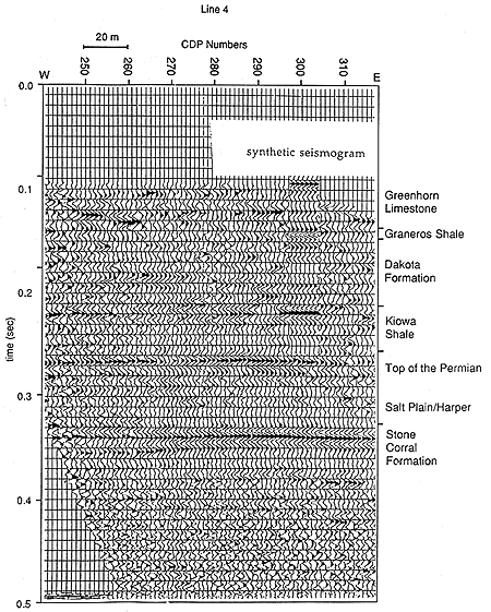
Figure C.33. Channel sand would be approved as a transparent zone if present at this location. A larger version of this figure is available.
2. Sandstones below the base of the Dakota Formation, including the Longford Member of the Kiowa Shale and the Cedar Hills, were resolvable and identified where reflections with frequencies above 180 Hz were recorded.
3. Resolution and data quality were site dependent. Best results are obtained when the data is collected on fresh exposures of Graneros Shale. Reflections of 200 Hz and higher were recorded at these sites. Sites that have dry alluvium at the surface are less desirable. These sites yielded reflection frequencies lower than 100 Hz. The worst sites are those directly on the Greenhorn Limestone. Low frequencies were recorded where the ground surface was stratigraphically higher than the Greenhorn Limestone.
4. The intermediate results obtained on lines 1 and 4 can be expected at most sites in central and western Kansas. At these intermediate sites the base of the Dakota Formation can be detected. If a channel sand similar to the one penetrated by the Haberer well is present it will have recognizable reflections from both the top and bottom interfaces. The level of resolution, however, will not allow the distinction of the base of the channel or base of the Dakota Formation from the underlying sandstones in the Kiowa Formation.
5. Geophones and shot holes located in the road ditch improved the resolution and the S/N ratio. Sources and receivers located on the road surface resulted in lower-quality data.
6. Record length and sampling rate adjusted to allow for the recording of reflections from the Stone Corral Formation allowed confident correlation of the four seismic lines. On a local scale it is acceptable to use the Stone Corral Formation for static corrections, which otherwise would be difficult. The seismic lines collected for this study can be used to help interpret seismic lines collected in the future. The characteristic reflection from the Stone Corral can easily be identified and used as a starting point to correlate seismic data.
7. The synthetic seismogram calculated from the Brundgardt sonic log greatly aided in the interpretation of line 4. The neutron porosity log, gamma ray log, and density log were used to create a pseudo sonic log for the Haberer well . The synthetic seismogram generated from the pseudo-sonic log aided in the interpretation of line 1 and line3. The neutron porosity log alone proved acceptable to calculate a pseudo-sonic log. Using the coefficients derived from the Brundgardt well logs, pseudo-sonic logs and synthetic seismograms can be generated from available well information in areas where seismic data are to be collected.
8. The F-K filtering program used on line 2 removed linear noise without creating artifacts. Linear moveout at the velocity of the noise to be removed before 2-D Fourier transformation and very smooth tapering were instrumental in not creating artificial coherency. The success of the filter indicates that if weather conditions had been better and some signal had been recorded with the linear noise, the filter could remove the noise increasing S/N ratio and allowing interpretation of the data. However, no amount of processing can uncover signal that was never recorded.
The low amount of signal recorded on line 2 was also a function of the dynamic range of the seismograph. The 12 bit fixed-point system has a potential dynamic range of 72 dB. This was not enough to record both the high amplitude coherent noise and any low amplitude signal that was present. F-k filtering could increase the number of sites where seismic reflection could detect the sandstone lenses in the Dakota Formation if the data were recorded with a seismograph with enough dynamic range to record both high amplitude coherent linear noise and low amplitude signal.
9. Areas stratigraphically higher than the Blue Hill Shale Member of the Carlile Shale have not been studied. As the depth to the Dakota Formation increases to the west, less energy and lower frequencies would be expected from reflections in the target interval. Thus, the data would not be better than the intermediate quality seen on line 1 and line 4. Most likely the data quality and resolution would be lower.