Kansas Geological Survey, Bulletin 47, pt. 3, originally published in 1943
Published with permission of C. Y. Thomas, General Manager, Military Chemical Works, Inc., Prime Contractors of the Jayhawk Ordnance Works.
Originally published in 1943 as Kansas Geological Survey Bulletin 47, pt. 3. This is, in general, the original text as published. The information has not been updated. An Acrobat PDF version (6.5 MB) is also available.
Participation of the State Geological Survey in planning and constructing the Jayhawk Ordnance Works deep water well was under the general administration of R. C. Moore, State Geologist, and John C. Frye, Assistant State Geologist.
Thanks and appreciation are expressed to the officials of the Jayhawk Ordnance Works; the Military Chemical Works, Inc.; F. H. McGraw and Co.; F. H. Freeto Construction Co.; and especially to Kenneth A. Spencer, Vice President and General Manager of the Pittsburg and Midway Coal Mining Co. (now President of the Military Chemical Works, Inc. and Prime Contractor of the Jayhawk Ordnance Works), and to C. Y. Thomas, Chief Engineer of the Pittsburg and Midway Coal Mining Co. (now Chief Engineer for the Jayhawk Ordnance Works), who made it possible for the State Geological Survey to aid in the development of a deep-well water supply for this important war industry, and who granted permission to publish the statistical information in this report. The writer also wishes to express his indebtedness to Clay Lewis, Assistant Engineer, and to C. A. Sherman, Office Engineer, both of the Ordnance works, for much valuable assistance in obtaining data. The manuscript for this report was reviewed critically by John C. Frye, Assistant State Geologist, and Dorothea Weingartner, editor for the State Geological Survey.
Plate 1—The Jayhawk Ordnance Works well in Cherokee County, Kansas.
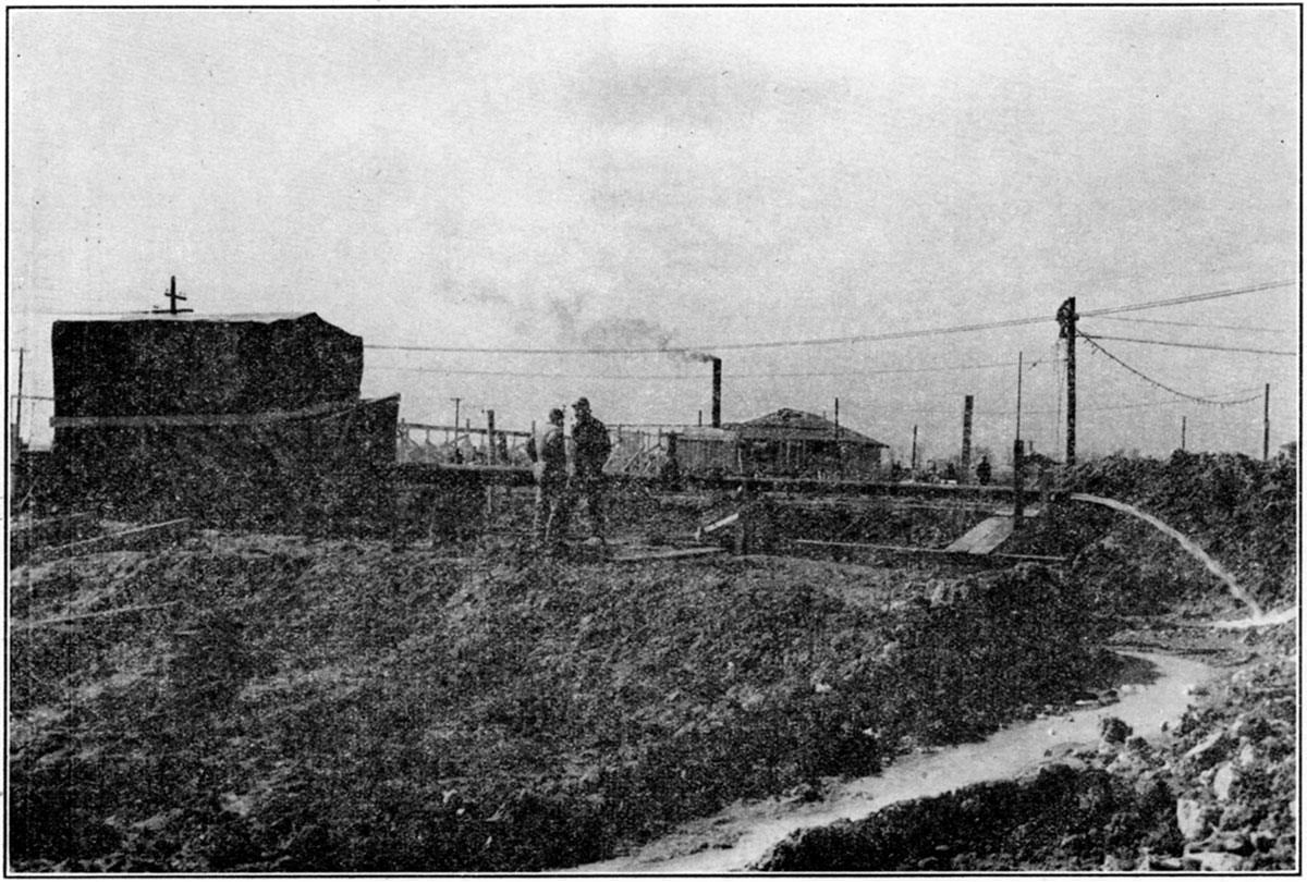
At the request of officials of the Jayhawk Ordnance Works, a representative of the State Geological Survey of Kansas supervised the drawing of plans and specifications and acted as consulting geologist during drilling operations for a deep water well. The well was begun at the Jayhawk Ordnance Works, in Cherokee county, Kansas, on December 16, 1941, and was completed on January 22, 1942.
The first rocks penetrated in the well are Mississippian in age. The deepest formation penetrated is the Gasconade of early Ordovician age. In southeastern Kansas, Mississippian rocks lie upon Ordovician rocks.
The most important water-producing formation encountered in the well is the Roubidoux of the Ordovician which was penetrated at 745 feet to 875 feet below the surface. The Roubidoux is a light gray, sandy dolomite. It contains two sandstone beds throughout southeastern Kansas. One sandstone bed is 25 feet thick and occurs at the base of the formation; the other is about 20 feet thick and is separated from the lower bed by about 50 feet of sandy dolomite. In favorable areas the sandstone beds and porous dolomites yield fair supplies of moderately hard water which is low in chloride. Other Ordovician formations, the Jefferson City and the Cotter, yield smaller amounts of water. The Burlington, Keokuk, and Reeds Spring formations of the Mississippian system contain large quantities of water. The water in the Mississippian rocks, however, is extremely hard because of considerable iron and iron and sulphur compounds. The water from the Mississippian rocks was cased off in the well under consideration. Permanent casing was set at 335 feet and was grouted with cement from the bottom of the casing to the surface of the ground.
This Ordnance well is the first deep water well in this district known to have been treated with acid. A pumping test was made before the well was acidized and additional tests were made after use of the acid. The tests indicated that the specific capacity of the well was increased more than four times as a result of acid treatment.
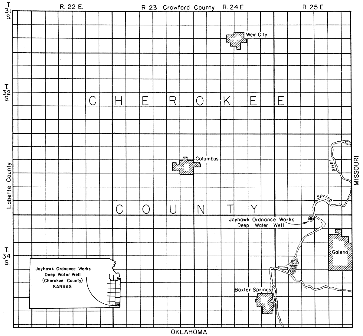
The Jayhawk Ordnance Works deep water well, NW cor. SE NE sec. 4, T. 34 S., R. 25 E., Cherokee county, Kansas, (fig. 1) is the first deep water well in the Tri-State area known to have been treated successfully with acid. The well was electrically logged and was test-pumped both before and after acid treatment.
Figure 1—Index map of Cherokee County, Kansas showing location of the Jayhawk Ordnance Works well.
During the 13 months that the well was being planned and drilled, members of the State Geological Survey of Kansas advised in the preparation of specifications and supplied geological . advice. They collected drill cuttings and water samples from various water-bearing formations and, finally, prepared this report in order that other war industries located in the Tri-State area, or in areas where similar water supply problems occur, may have a complete record of the drilling method and treatment of a deep water well. Also included in this report is a part of the detailed information gathered in ,1941 in a survey of ground-water conditions in south-eastern Kansas, a preliminary outline of which was published in 1941 (Abernathy).
The Geological Survey began to study the problem on February 28, 1941, when C. Y. Thomas, Chief Engineer of the Jayhawk Ordnance Works, requested information relative to a groundwater supply in Crawford and Cherokee counties. On March 3, 1941, the Survey made a preliminary report which was immediately followed with additional investigation.
In conference with War Department officials and Army Engineers, the Survey furnished much advice relative to electric logging, selection of points for temporary and permanent casing, cementing, acid treatment, setting the deep-well pump, and testing the well capacity. This work, begun August 1, 1941, was completed March 12, 1942.
Rocks of Mississippian age crop out on the reservation of the Jayhawk Ordnance Works, which is located a few miles east and south of the outcrop of the dis conformity between rocks of the Mississippian and Pennsylvanian subsystems. The disconformable surface between Mississippian limestone and Pennsylvanian sediments is a very irregular one, with a local relief of 100 or more feet.
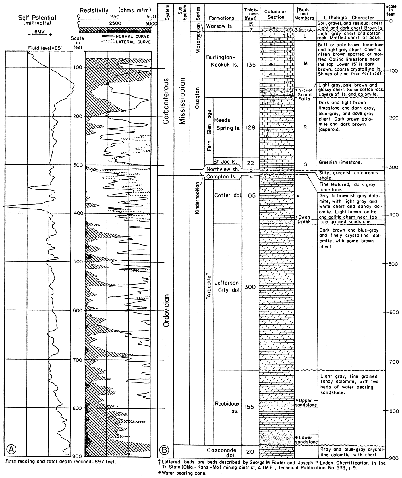
Mississippian rocks in this part of Kansas lie disconformably on rocks of Ordovician age. The subsurface formations of Mississippian and Ordovician age penetrated by the deep well at the Jayhawk Ordnance Works are shown in figure 2. The rocks of Ordovician age in the well consist mostly of cherty dolomite, some sandy dolomite, and sandstone. The rocks of the Mississippian subsystem consist mostly of cherty limestone, limestone, and a thin bed of shale.
The correlation shown in figure 2 is my own, made with the aid of insoluble residues and cuttings. Wallace Lee, Federal and State Geological Surveys, J. G. Grohskopf, and O. R. Grawe, Missouri Bureau of Geology and Water Resources, and R. P. Keroher, formerly of the State Geological Survey of Kansas, separately studied residues and cuttings and made correlations that do not agree in all respects.
Figure 27—A. Electrical log, showing self-potential and resistivity curves. B. Columnar section of rocks penetrated by the Jayhawk Ordnance Works deep water well.
Gasconade formation
The oldest rocks penetrated by the deep well at the Jayhawk Ordnance Works belong to the Gasconade formation. Grohskopf-Gott identified 20 feet of Gasconade rocks in a correlation made by an examination of the siliceous residues. Cuttings from Gasconade rocks in this well consist of: (1) fine crystalline, brown and gray dolomite; (2) light gray and light brown granular dolomite; (3) glassy gray chert; (4) white and light gray vitreous chert; (5) clear quartz sand grains; (6) pyrite; and (7) calcite. Some siliceous oolite and light gray chert are found in the siliceous residues of these rocks.
Roubidoux formation
The Roubidoux formation is commonly described as consisting of alternating beds of dolomite and sandstone. In southeastern Kansas the formation consists of brown-gray dolomite and two sandstone members.
Table 1—Driller's time-log for deep water well at the Jayhawk Ordnance Works, NW cor. SE NE sec. 4, T. 34 S., R. 25 E., Cherokee county, Kansas (Altitude: top of well, 854.33 feet; bottom of hole, -46.67 feet. Drilling began December 16, 1941; completed January 22, 1942. Static water level in completed well, 65 feet below land surface.)
| Date | Formation | Thickness (feet) |
Total depth (ft.) |
Diameter of hole (in.) |
|---|---|---|---|---|
| 1941 | ||||
| Dec. 16 | Clay | 12 | 12 | 20 |
| Gravel | 2 | 14 | 20 | |
| Flint, blue, gray, and white | 4 | 18 | 20 | |
| Flint, gray, and limestone | 2 | 20 | 20 | |
| Dec. 19 | (Set 20 feet of 18 inch pipe) | |||
| Dec. 20 | Flint, gray, and limestone | 15 | 35 | 16 |
| Flint, white, gray, and blue | 2 | 37 | 16 | |
| Flint, white, gray, and blue | 3 | 40 | 16 | |
| Dec. 21 | Flint, blue-gray | 5 | 45 | 16 |
| Dec. 22 | Flint, blue-gray, and zinc "shines" | 2 1/2 | 47 1/2 | 16 |
| Limestone, gray, and flint, gray | 2 1/2 | 50 | 16 | |
| Dec. 23 | Limestone, gray, and flint, gray | 7 | 57 | 16 |
| Limestone, gray | 7 | 64 | 16 | |
| Dec. 24 | Limestone, gray, and flint, gray | 11 | 75 | 16 |
| Limestone, gray | 3 | 78 | 16 | |
| Dec. 25 | Limestone, gray | 32 1/2 | 1101h | 16 |
| Dec. 26 | Limestone, gray | 3 1/2 | 114 | 16 |
| Limestone, gray, and flint, gray | 12 | 126 | 16 | |
| Flint, white and gray | 3 | 129 | 16 | |
| Dec. 27 | Flint, gray | 11 | 140 | 16 |
| Flint, gray, and limestone, gray | 6 | 146 | 16 | |
| Flint, light blue and gray, and zinc traces | 4 | 150 | 16 | |
| Limestone, gray-brown, and pyrite | 7 | 157 | 16 | |
| Limestone, brown and white | 3 | 160 | 16 | |
| Flint, white-gray and blue | 7 | 167 | 16 | |
| Dec. 28 | Limestone, brown and white | 2 | 169 | 16 |
| Flint, white and blue, and limestone, dark | 5 | 174 | 16 | |
| Flint, blue and gray, and limestone, gray | 6 | 180 | 16 | |
| Dec. 29 | Flint, blue and gray, and limestone, gray | 9 | 189 | 16 |
| Flint, blue, and limestone, gray | 11 | 200 | 16 | |
| (Reduced hole from 16" to 13" at 200') | ||||
| Limestone, blue-gray, and flint, gray | 5 | 205 | 13 | |
| Limestone, gray, and flint, gray | 4 | 209 | 13 | |
| (Water level, 40' from top) | ||||
| Dec. 30 | Limestone, gray, and flint, blue and gray | 9 | 218 | 13 |
| Limestone, flint, and shale, dark | 3 | 221 | 13 | |
| Limestone, gray, and flint, blue | 14 | 235 | 13 | |
| Limestone, gray, and flint, gray | 9 | 244 | 13 | |
| Limestone, gray, and flint, gray | 6 | 250 | 13 | |
| Dec. 31 | Limestone, gray, and flint, gray | 5 | 255 | 13 |
| Limestone, gray | 5 | 260 | 13 | |
| 1942 | ||||
| Jan. 1 | Running pipe and welding joints (temporary casing) | |||
| Jan. 2 | Running pipe and welding joints (temporary casing) | |||
| Jan. 3 | Running pipe and welding joints (temporary casing) | |||
| Jan. 4 | Running pipe and welding joints (temporary casing) | |||
| Jan. 5 | Limestone, gray | 10 | 270 | 10 |
| Limestone, gray, and flint, blue | 5 | 275 | 10 | |
| Flint, blue-gray and white | 5 | 280 | 10 | |
| Limestone, gray and green, and flint, gray | 5 | 285 | 10 | |
| Limestone, gray | 6 | 291 | 10 | |
| Jan. 6 | Limestone, gray | 14 | 305 | 10 |
| Limestone, green | 6 | 311 | 10 | |
| Limestone, gray and green | 4 | 315 | 10 | |
| Limestone, gray, and flint | 15 | 330 | 10 | |
| Limestone, gray, and flint, gray . | .5 | 335 | 10 | |
| Flint, gray and white, and limestone, gray | 6 | 341 | 10 | |
| Jan. 7 | Flint, white and blue, and limestone, gray | 31 | 372 | 10 |
| Limestone, gray, and flint, gray | 18 | 390 | 10 | |
| Limestone, gray, and flint, gray-blue | 5 | 395 | 10 | |
| (120 gal. in 5 min. 25 ft. draw down) | ||||
| (Pulled temporary casing) | ||||
| (Started reaming hole) | ||||
| Jan. 9 | (Reamed hole) | 56 | 316 | |
| Jan. 10 | (Reamed hole) | 19 | 335 | 8 1/4-13 |
| (Reamed hole) | 21 | 356 | 8 1/4-10 | |
| Jan. 11 | (Reamed hole) | 34 | 390 | 8 1/4-10 |
| (Reamed hole) | 5 | 395 | 8 1/4-10 | |
| Jan. 12 | Flint, white and blue | 3 | 398 | 10 |
| Limestone, gray | 3 | 401 | 10 | |
| Limestone, gray, and flint, blue | 9 | 410 | 10 | |
| Limestone, gray, and sandstone | 22 | 422 | 10 | |
| Limestone, gray, and sandstone, and flint, gray | 13 | 435 | 10 | |
| Limestone, gray, and flint, gray | 5 | 440 | 10 | |
| Flint, white and blue, and flint, gray | 24 | 464 | 10 | |
| Jan. 13 | Flint, white and blue, and limestone, gray | 8 | 472 | 10 |
| Limestone, gray, and flint, white | 23 | 495 | 10 | |
| Jan. 14 | Limestone, gray, and flint, white | 20 | 515 | 10 |
| Limestone, gray, and flint, gray | 31 | 546 | 10 | |
| Jan. 15 | Limestone, gray, and flint, gray | 24 | 570 | 10 |
| Flint, blue-gray, and limestone, gray | 30 | 600 | 10 | |
| Limestone, brown, and flint, white | 12 | 612 | 10 | |
| Jan. 16 | Limestone, brown, and flint, white | 23 | 635 | 10 |
| Limestone, brown, and flint, white and blue | 20 | 655 | 10 | |
| Flint, blue-gray, and limestone, brown | 10 | 665 | 10 | |
| Limestone, gray, and flint, gray | 5 | 670 | 10 | |
| Limestone, brown, and flint, gray | 7 | 677 | 10 | |
| Jan. 17 | Limestone, brown, and flint, gray | 21 | 698 | 10 |
| Limestone, brown sandy | 12 | 710 | 10 | |
| Flint, white-gray, and limestone, gray | 10 | 720 | 10 | |
| Flint, gray-white-blue | 10 | 730 | 10 | |
| Jan. 18 | Flint, gray-white and blue | 17 | 747 | 10 |
| Limestone, gray sandy calcite | 8 | 755 | '10 | |
| Limestone, gray calcite | 7 | 762 | 10 | |
| Limestone, gray-white-blue | 3 | 765 | 10 | |
| Limestone, gray-white and blue | 10 | 775 | 10 | |
| Jan. 19 | Limestone, gray, and flint, blue and white | 7 | 782 | 10 |
| Limestone, gray, flint, gray-white, and sandstone | 3 | 785 | 10 | |
| Sandstone | 7 | 792 | 10 | |
| Limestone, sandy | 13 | 805 | 10 | |
| Jan. 20 | Limestone, sandy | 20 | 825 | 10 |
| Flint, gray-white, and limestone, gray | 10 | 835 | 10 | |
| Flint, gray-white | 5 | 840 | 10 | |
| Limestone, sandy | 9 | 849 | 10 | |
| Jan. 21 | Sandstone | 24 | 873 | 10 |
| Jan. 22 | Sandstone | 3 | 876 | 10 |
| Limestone, very little sandstone | 6 | 882 | 10 | |
| Limestone, sandy gray | 13 | 895 | 10 | |
| Limestone, gray, S.L.M. | 6 | 901 | 10 | |
In the Jayhawk Ordnance Works well, the Roubidoux formation is 155 feet thick. The top of the formation was reached at a depth of 720 feet. The uppermost sandstone member is 15 feet thick and occurs in the middle of the formation. The lower sandstone member is about 25 feet thick and occurs at the base of the formation. Both sandstone members contain subangular to rounded quartz grains, medium to coarse in size. The grains are unfrosted and many show concentric coatings of silica, the results of secondary enlargement. Chert, which is dense and glassy and light gray and light blue, occurs abundantly in the Roubidoux formation. The average content of insoluble residue in the Roubidoux dolomite is 74.82 percent. Some of the chert in the siliceous residues is dead white in color. Dark gray, siliceous oolite is common to the chert found in the siliceous residues. The dolomite in the Roubidoux has fine granular texture and is brown and gray.
Jefferson City formation
The Jefferson City formation comprises a finely crystalline, cherty dolomite, dark brown and blue-gray in color, 300 feet thick in the Jayhawk Ordnance Works well. The top of the formation was reached at a depth of 420 feet.
Chert occurs abundantly in the Jefferson City formation. It is light in color, translucent, and has a waxy luster. This peculiar chert is characteristic of the Jefferson City. The electric log and the drillers' time log indicate that the formation consists of fairly porous dolomite and streaks or thin bands of impervious chert. The average content of insoluble material in the Jefferson City formation is 84.58 percent.
Cotter formation
The Cotter formation lies above the Jefferson City formation and is the uppermost Ordovician formation in the well. The Cotter formation consists of tan and light gray, sandy, cherty dolomite and some thin beds of sandstone. The total thickness of the Cotter formation in the wells is 105 feet. The top was reached at 314 feet.
Chert of the Cotter formation is gray and brown. Pyrite and concentrically banded cherts are common. Oolitic chert, brown in color, and brown oolite coated with fine quartz crystals are very characteristic of the Cotter formation. Vugs and cavities lined with quartz crystals are common in the upper members of the formation. The average acid insoluble content of the Cotter dolomite is 85.75 percent.
The base of the formation is marked by 10 feet of sandy dolomite (Swan Creek).
Pre-Carboniferous unconformity
Southeastern Kansas lies on the Chautauqua Arch, and in several counties Mississippian rocks lie on rocks of medial and early Ordovician age. Devonian, Silurian, and late Ordovician deposits were eroded from most of the Chautauqua Arch before burial under Mississippian sediments.
Subsurface Mississippian rocks of Kansas have been studied by Lee (1940); his investigation included studies of cuttings from several wells in the same general area of the Jayhawk Ordnance well.
Compton formation
Beds assigned to the Compton formation consist of bluish gray, compact, fine-grained limestone. In the Jayhawk Ordnance Works well the formation is 5 feet thick. The upper beds of the formation merge into the soft bluish green shale of the Northview formation.
Northview formation
The well cuttings of Northview shale from the Jayhawk Ordnance Works well consists of soft, bluish green shale, 5 feet thick. This shale is easily distinguished from the shale of other associated formations by its color and plastic, sticky properties.
St. Joe formation
The St. Joe formation includes the beds between the overlying Reeds Spring formation and the underlying Northview formation. In the Jayhawk Ordnance Works well, rocks of this formation consist of beds of light bluish gray, fine-grained, and compact limestone, 25 feet thick. The formation contains some chert. It is distinguished from the overlying formations by its smaller content of chert, and from the lower formations by its larger content of limestone and the absence of dolomite.Reeds Spring formation
The Reeds Spring formation includes the beds between the overlying Burlington formation and the St. Joe limestone. It consists of dense, hard, fine-grained, bluish limestone, some dolomitic limestone, some dolomite, some siltstone, an abundance of chert, dark brown and dark gray in color and 125 feet thick in the Jayhawk Ordnance Works well.Burlington-Keokuk formations
The Burlington-Keokuk formations include all of the beds between the overlying Warsaw and the Reeds Spring formations. The Burlington-Keokuk formations are separated from the Warsaw by an unconformity. The formations consist of gray and tan limestone, dolomite, and an abundance of chert. In the Jayhawk Ordnance Works well the formations are 135 feet thick. The base of the formation is the Grand Falls chert member, 35 feet thick. The chert is speckled-light gray, dove gray, ash gray, and brown. The Grand Falls member consists of 80 percent insoluble material (chert), gray limestone, and some gray dolomitic limestone. In the Tri-State mining district the Grand Falls member is designated as "N, O, P, and Q" beds, or the "sheet-ground."
M bed overlies the N, 0, P, and Q beds. It is characterized by light brown oolite in its upper members, light brown limestone, and a low content of chert. In the Jayhawk Ordnance Works well, M bed is 81 feet thick.
L bed, 20 feet thick, overlies the M bed and is the uppermost bed of the Burlington-Keokuk formations. In the Jayhawk Ordnance Works well it consists of light gray limestone and white, leached chert, known as "cotton rock."
Warsaw formation
The Warsaw formation in the Jayhawk Ordnance Works well consists of light and dark gray chert with some gray limestone. The base of the formation is marked by the J bed (Cowley) (Lee, 1940, p. 81), which consists of dark brown limestone and flint with some glauconite. The thickness of rocks assigned to the Warsaw formation is 88 feet. About 12 feet of detrital material overlies the Warsaw rocks.
While the well was being drilled, the depth to water level was measured using a steel line each time a different formation was penetrated, or at intervals within a given formation. The results are given in table 2. After drilling had reached a depth of 260 feet, the temporary casing was set to this depth preventing any effect of the hydrostatic pressure of water in the Reeds Spring limestone on that of water in the lower formations. The well was drilled from 260 feet to the bottom without using casing in this part of the hole; therefore, the water-level measurements made below a depth of 260 feet do not necessarily represent the hydrostatic pressure of water in the particular formation reached by the drill; but they do represent the resultant head of water from all formations penetrated below 260 feet. Water-bearing formations having a lower head than the resultant probably were receiving water from the well; those having a higher head probably were contributing water. Moreover, the accuracy of individual water-level measurements doubtless was affected by the quantity and period of bailing, the length of time the well was allowed to rest before the measurements were made, and the possible sealing effect of drill cuttings in the bottom of the hole.
Table 2—Depths of rock formations penetrated and corresponding static water levels
| Rock formation | Depth of formation (ft.) |
Static water level (feet below land surface) |
|---|---|---|
| Warsaw | 0-110 | dry |
| Burlington and Keokuk | 110-145 | dry |
| Reeds Spring | 145-285 | 40 |
| Cotter | 315-320 | 195 |
| Cotter | 320-330 | 150 |
| Cotter | 330-335 | 65 |
| Cotter | 335-410 | 57 |
| Swan Creek | 410-420 | 57 |
| Jefferson City | 420-472 | 60 |
| Jefferson City | 472-495 | 65 |
| Jefferson City | 495-715 | 60 |
| Roubidoux | 715-747 | 60 |
| Roubidoux | 747-850 | 70 |
| Roubidoux | 850-862 | 63 |
| Roubidoux | 862-865 | 68 |
| Roubidoux | 865-876 | 67 |
| Gasconade | 876-901 | 65 |
The drill cuttings were tested for solubility by the Halliburton Oil Well Cementing Company and also by the State Geological Survey of Kansas. The analyses by the Geological Survey, which are very similar to those made by the Halliburton Oil Well Cementing Company, are given in table 3.
Table 3—Solubility in (hydrochloric acid) of drill cuttings from Jayhawk Ordnance Works water well. (Kansas Geological Survey No. 3108. Analyses by R. P. Keroher.)
| Depth (feet) |
Solubility (percent) |
|---|---|
| 50-52.5 | 35 |
| 52.5-55 | 21 |
| 55-57 | 87 |
| 57-60 | 50 |
| 60-64 | 48 |
| 64-66 | 47 |
| 66-68 | 64 |
| 68-70 | 94 |
| 70-72.5 | 65 |
| 72.5-75 | 95 |
| 75-78 | 99 |
| 78-83 | 99 |
| 83-87.5 | 86 |
| 87.5-91 | 86 |
| 91-95 | 99 |
| 95-100 | 99 |
| 100-104 | 98 |
| 104-108 | 79 |
| 108-110.5 | 56 |
| 110.5-114 | 53 |
| 114-117 | 33 |
| 117-120 | 35 |
| 120-123 | 68 |
| 123-126 | 25 |
| 126-129 | 29 |
| 129-133 | 32 |
| 133-137 | 31 |
| 137-140 | 25 |
| 140-143 | 26 |
| 143-145 | 25 |
| 145-150 | 6 |
| 150-154 | 2 |
| 154-157 | 1 |
| 157-160 | 45 |
| 160-162 | 57 |
| 162-164 | 37 |
| 164-167 | 54 |
| 167-170 | 57 |
| 170-174 | 41 |
| 174-177 | 42 |
| 177-180 | 45 |
| 180-184.5 | 35 |
| 184.5-189 | 49 |
| 189-192 | 53 |
| 192-196 | 49 |
| 196-200 | 41 |
| 200-202 | 31 |
| 202-205 | 21 |
| 205-209 | 36 |
| 209-213 | 28 |
| 213-219 | 28 |
| 219-221 | 29 |
| 221-225 | 39 |
| 225-229 | 19 |
| 229-234 | |
| 234-239 | 57 |
| 239-244 | 79 |
| 244-250 | 91 |
| 250-255 | 99 |
| 255-260 | 99 |
| 260-262 | 98 |
| 262-265 | 99 |
| 265-270 | 87 |
| 270-275 | 56 |
| 275-280 | 58 |
| 280-285 | 76 |
| 285-290 | 99 |
| 290-295 | 99 |
| 295-300 | 99 |
| 300-305 | 99 |
| 305-310 | 95 |
| 310-315 | 85 |
| 315-320 | 90 |
| 320-325 | 71 |
| 325-330 | |
| 330-335 | 91 |
| 335-340 | 86 |
| 340-345 | 61 |
| 345-350 | 57 |
| 350-355 | 91 |
| 355-360 | 89 |
| 360-365 | 89 |
| 365-370 | 83 |
| 370-375 | 87 |
| 375-380 | 93 |
| 380-385 | 95 |
| 385-390 | 93 |
| 390-395 | 90 |
| 395-400 | 84 |
| 400-405 | 88 |
| 405-410 | 92 |
| 410-415 | 90 |
| 415-420 | 95 |
| 420-425 | 98 |
| 425-430 | 93 |
| 430-435 | 97 |
| 435-440 | 86 |
| 440-445 | 95 |
| 445-450 | 90 |
| 450-455 | 93 |
| 455-460 | 84 |
| 460-465 | 84 |
| 465-470 | 68 |
| 470-475 | 78 |
| 475-480 | 80 |
| 480-485 | 91 |
| 485-490 | 91 |
| 490-495 | 92 |
| 495-500 | 89 |
| 500-505 | 94 |
| 505-510 | 82 |
| 510-515 | 72 |
| 515-520 | 72 |
| 520-525 | 92 |
| 525-530 | 87 |
| 530-535 | 81 |
| 535-540 | 77 |
| 540-545 | 62 |
| 545-550 | 62 |
| 550-555 | 84 |
| 555-560 | 86 |
| 560-565 | 86 |
| 565-570 | 78 |
| 570-575 | 85 |
| 575-580 | 79 |
| 580-585 | 82 |
| 585-590 | 73 |
| 590-595 | 76 |
| 595-600 | 83 |
| 600-605 | 85 |
| 605-610 | 97 |
| 610-615 | 97 |
| 615-620 | 70 |
| 620-625 | 71 |
| 625-630 | 72 |
| 630-635 | 94 |
| 635-640 | 96 |
| 640-645 | 88 |
| 645-650 | 90 |
| 650-655 | 72 |
| 655-660 | 78 |
| 660-665 | 82 |
| 665-670 | 97 |
| 670-675 | 98 |
| 675-680 | 99 |
| 680-685 | 99 |
| 685-690 | 98 |
| 690-695 | 98 |
| 695-700 | 76 |
| 700-705 | 78 |
| 705-710 | 79 |
| 710-715 | 69 |
| 715-720 | 80 |
| 720-725 | 41 |
| 725-730 | 88 |
| 730-735 | 95 |
| 735-740 | 95 |
| 740-745 | 94 |
| 745-750 | |
| 750-755 | 99 |
| 755-760 | 86 |
| 760-765 | 95 |
| 765-770 | 85 |
| 770-780 | |
| 780-782 | 86 |
| 782-785 | 53 |
| 785-790 | 18 |
| 790-795 | 57 |
| 795-800 | 81 |
| 800-805 | 89 |
| 805-810 | 89 |
| 810-815 | 98 |
| 815-820 | 98 |
| 820-825 | 98 |
| 825-830 | 79 |
| 830-835 | 71 |
| 835-840 | 63 |
| 840-845 | 95 |
| 845-850 | 93 |
| 850-855 | 76 |
| 855-860 | 65 |
| 860-865 | 53 |
| 865-870 | 9 |
| 870-875 | 11 |
| 875-880 | 98 |
| 880-885 | 97 |
| 885-890 | 95 |
| 890-895 | 99 |
| 895-901 | 91 |
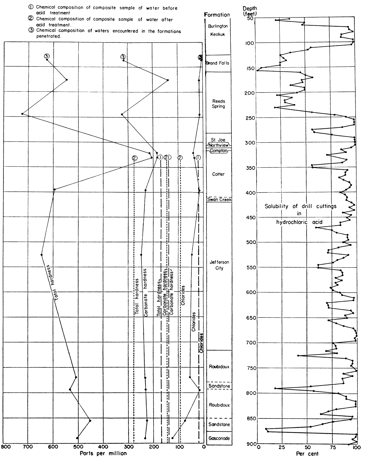
A curve showing the percentage of soluble material in each sample is given in figure 3. The analyses indicate that the lower part of the Burlington (Keokuk) limestone has low solubility, and the Grand Falls chert member at the base of the Burlington is nearly insoluble. The upper part of the Reeds Spring limestone also has low solubility, The remainder of the curve shows high solubility of the formations penetrated, with the exception of a zone of dolomitic limestone in the Reeds Spring at a depth of 270 feet, a zone in the Cotter dolomite at 335 feet, a few minor zones in the Jefferson City dolomite, a relatively insoluble zone at a depth of 720 feet at the base of the Jefferson City, and another in the upper sandstone of the Roubidoux at a depth of 790 feet. This upper sandstone of the Roubidoux, though not as soluble as the dolomitic zones of the formation, has an average solubility of about 70 percent, indicating that its porosity could be improved by acid treatment. The lower sandstone of the Roubidoux, at a depth of 870 feet, has a solubility of about 9 percent, indicating that acid treatment would be ineffective on this bed.
Figure 3—Solubility of rocks penetrated and the hardness and chloride content of waters contained in the various formations of the Jayhawk Ordnance Works deep water well.
In the development of a deep-well water supply, it is helpful to have information on the porosity and degree of saturation of the formations. Information of this type may be obtained from cores cut from the formations or from electric well logs. Some information already was available from several hundred deep water wells in this area, so it was not deemed advisable to take a core of each water-bearing formation; however, an electric log was made of the hole after drilling was completed.
The deep well at the Jayhawk Ordnance Works was electrically logged on January 24,1942, by the Schlumberger Well Surveying Corporation. A copy of the electrical log is given in figure 2. The self-potential curve indicates the presence of very porous zones at depths of 65 feet to 110 feet, 290 feet to 305 feet, and 375 feet to 400 feet. The normal resistivity curve indicates the base of the Mississippian limestones at 316 feet, the base of the Jefferson City and the top of the Roubidoux at 705 feet. This curve also indicates that both sandstones of the Roubidoux should produce water and that the lower sandstone probably would be more productive than the upper. The curve indicates that between the depths of 415 feet and 705 feet the Jefferson City dolomite is broken or is made up of a number of beds, each having different resistivity. Some of the beds are indicated to be porous and some fairly porous; the porous beds probably contain water.
The well was drilled by the Cascho and Pugh Drilling Company, using a No. 5 1/2 Keystone cable-tool drill. Drilling was begun on December 16,1941, and completed on January 22, 1942.
A hole 20 inches in diameter was drilled to a depth of 20 feet and lined with 20 feet of temporary 18-inch casing. The hole was drilled to a diameter of 16 inches from a depth of 20 to 200 feet, 13 inches from a depth of 200 to 260 feet, and 8 inches from a depth of 260 to 395 feet.
The 8-inch hole was reamed to a diameter of 13 inches between the depths of 260 and 335 feet, and the permanent 10-inch casing was placed from the surface to a depth of 335 feet, in order to exclude the hard water of the Reeds Spring limestone and the water at the base of the Mississippian formations and at the top of the Cotter dolomite, which contains considerable hydrogen sulphide. The remainder of the 8-inch hole (between depths of 335 and 395 feet) was reamed to a diameter of 10 inches. Drilling was then resumed using a 10-inch bit, and the well was deepened to a total depth of 901 feet.
The driller's time-log, indicating the nature of the formation drilled and the size and depth of the hole drilled each day, is given in table 1.
After drilling had been completed, the 10 1/2-inch temporary casing was removed from the hole and a 10 1/2-inch wooden plug was cemented (with five bags of Hi-Early cement) into the hole just below the casing point, at a depth of 335 feet. The plug was driven into place with drilling tools, and the cement was placed by using a dart-valve bailer.
After the cement set for 24 hours, the lengths of permanent casings were welded together and lowered into the hole. The fifteen lengths of 10-inch I.D. casing had a total length of 337 feet and 11 inches; but after deducting approximately 3 feet of casing lost because of poor threads, the total length of permanent casing set in the hole was about 334 feet and 11 inches.
The Halliburton Oil Well Cementing Company then filled with cement the annular space between the casing and the hole. Two hundred eighty bags of Hi-Early cement, 14 bags of Aquajel, and 350 pounds of Flocele were mixed and put into the casing. A bridging plug was placed on top of the cement. The plug was pushed to the bottom, causing the cement to be forced out of the bottom and upward around the casing, filling all the space and openings between the walls of the hole and the casing. Several hundred pounds of the cement was forced out of the top of the hole, indicating that all of the space between the walls of the hole. and the casing had been filled.
After setting for 72 hours, the remaining cement was drilled out of the casing and the hole was cleaned out for about 3 feet below the casing bottom. The bailer was run once each hour for a period of 12 hours to test for a water leak at the bottom of the casing. No water came into the hole during this test, and the hole was cleaned out to a depth of 901 feet, its total depth.
All pumping tests were made using a Deming deep well turbine pump, comprising 18 stages of 10-inch bowls, and a direct connected 440 volt, 60 cycle, 100 h.p., U. S. Electric motor. The pump was set below 450 feet of discharge pipe, and 10 feet of suction pipe was added below the pump bowls. Before the first pumping test the static depth to water level was measured with a steel line and found to. be 65 feet. During the pumping tests, the level of the water in the hole was recorded by means of an air line extending into the well and attached to an air gauge marked in feet. The discharge of the well was measured by the orifice method, using a 3-inch orifice at the end of a 6-inch horizontal discharge pipe, 20 feet long, and a gauge for measuring the water pressure behind the orifice. The tests were made under the supervision of the writer and Roy A. Cobb, of the Deming Pump Company.
The first pumping test was made on February 25, 1942. When the pump was first started, the water level dropped to the bottom of the suction pipe after about one minute and 30 seconds of pumping, indicating that the rate of pumping was too great for the well. Back pressure was then put onto the discharge line by partly closing a gate valve until the level of the water in the well remained over the bowls of the pump while the pump was in operation. This discharge pressure was about 180 pounds to the square inch and the pumping water level was about 388 feet. The results given in table 4 indicate that after 19 hours of pumping, the well yielded only 154 gallons a minute with a draw-down of 323 feet, or only about. 0.48 gallon a minute per foot of draw-down. The pumping test was continued for a total of 26 hours and 22 minutes, but the rate of discharge was increased slightly after 19 hours of pumping.
Table 4—Pumping test of well before acid treatment. (February 24 and 25, 1942. Static water level, 65 feet; temperature of water, 65° F.)
| Time | Water gauge (inches) |
Discharge (gal. per minute) |
Discharge pressure (pounds) |
Pumping head (feet) |
Air gauge (ft. water) |
Depth to water level (feet) |
Drawdown (feet) |
|---|---|---|---|---|---|---|---|
| February 24 | |||||||
| 10:00 a.m. | 25. | 168 | 100 | 590 | 113 | 360 | 295 |
| 10:05 | 24.5 | 165 | 125 | 674 | 87 | 387 | 322 |
| 10:10 | 24. | 166 | 160 | 781 | 61 | 413 | 348 |
| 10:15 | 24. | 166 | 162 | 792 | 54 | 420 | 355 |
| 10:20 | 24. | 166 | 162 | 792 | 54 | 420 | 355 |
| 10:30 | 24. | 166 | 162 | 793 | 53 | 421 | 356 |
| 11:00 | 24. | 166 | 162 | 793 | 53 | 421 | 356 |
| 11:30 | 24. | 166 | 165 | 802 | 51 | 423 | 358 |
| 12:00 m. | 24. | 166 | 165 | 802 | 51 | 423 | 358 |
| 12:30 p.m. | 20.5 | 152 | 180 | 832 | 56 | 418 | 353 |
| 1:00 | 20.5 | 152 | 180 | 807 | 81 | 393 | 328 |
| 1:30 | 20.5 | 152 | 180 | 797 | 91 | 383 | 318 |
| 1:35 | 33. | 187 | 809 | 460 | 395 | ||
| 1:45 | 27. | 170 | 150 | 800 | 474 | 409 | |
| 4:00 | 21.5 | 158 | 180 | 802 | 82 | 392 | 327 |
| 4:30 | 21. | 157 | 175 | 794 | 82 | 394 | 329 |
| 5:00 | 20. | 150 | 190 | 820 | 91 | 383 | 318 |
| 5:30 | 20.5 | 153 | 185 | 808 | 91 | 383 | 318 |
| 6:00 | 20.5 | 153 | 185 | 803 | 96 | 378 | 313 |
| 6:30 | 21.5 | 156 | 172 | 793 | 76 | 398 | 333 |
| 7:00 | 21.5 | 156 | 175 | 770 | 76 | 368 | 305 |
| 7:30 | 20. | 150 | 180 | 798 | 90 | 384 | 319 |
| 8:00 | 20.5 | 153 | 180 | 798 | 90 | 384 | 319 |
| 8:30 | 20.5 | 153 | 180 | 798 | 90 | 384 | 319 |
| 9:00 | 20.5 | 153 | 180 | 798 | 90 | 384 | 319 |
| 9:30 | 20.5 | 153 | 183 | 804 | 90 | 384 | 319 |
| 10:00 | 20. | 150 | 185 | 808 | 91 | 383 | 318 |
| 10:30 | 21. | 157 | 180 | 799 | 89 | 385 | 320 |
| 11:00 | 21. | 157 | 180 | 799 | 89 | 385 | 320 |
| 11:30 | 20.5 | 153 | 180 | 799 | 89 | 385 | 320 |
| 12:00 | 20.75 | 154 | 180 | 802 | 86 | 388 | 323 |
| February 25 | |||||||
| 12:30 a.m. | 20.75 | 154 | 180 | 802 | 86 | 388 | 323 |
| 1:00 | 20.75 | 154 | 180 | 802 | 86 | 388 | 323 |
| 1:30 | 20.75 | 154 | 180 | 802 | 86 | 388 | 323 |
| 2:00 | 20.75 | 154 | 180 | 802 | 86 | 388 | 323 |
| 2:30 | 20.75 | 154 | 180 | 802 | 86 | 388 | 323 |
| 3:00 | 20.75 | 154 | 180 | 802 | 86 | 388 | 323 |
| 3:30 | 20.75 | 154 | 180 | 802 | 86 | 388 | 323 |
| 4:00 | 20.75 | 154 | 180 | 802 | 86 | 388 | 323 |
| 4:30 | 20.75 | 154 | 180 | 802 | 86 | 388 | 323 |
| 5:00 | 20.75 | 154 | 180 | 802 | 86 | 388 | 323 |
| 5:30 | 20.5 | 153 | 176 | 800 | 88 | 396 | 331 |
| 6:00 | 20.5 | 153 | 178 | 805 | 88 | 396 | 331 |
| 6:30 | 20.5 | 153 | 180 | 802 | 86 | 388 | 323 |
| 7:00 | 20.5 | 153 | 180 | 802 | 86 | 388 | 323 |
| 7:30 | 20.5 | 153 | 180 | 802 | 86 | 388 | 323 |
| 8:00 | 20.5 | 153 | 180 | 802 | 86 | 388 | 323 |
| 8:30 | 21. | 156 | 180 | 806 | 82 | 392 | 327 |
| 9:00 | 20.5 | 153 | 175 | 790 | 86 | 388 | 323 |
| 9:30 | 20.5 | 153 | 175 | 790 | 86 | 388 | 323 |
| 10:00 | 22.5 | 156 | 160 | 786 | 65 | 368 | 303 |
| 10:15 | 24.5 | 165 | 150 | 779 | 51 | 434 | 369 |
| 10:30 | 24.5 | 165 | 150 | 779 | 434 | 369 | |
| 11:00 | 24.5 | 165 | 150 | 779 | 434 | 369 | |
| 11:15 | 24. | 161 | 150 | 779 | 434 | 369 | |
| 11:30 | 24:5 | 165 | 150 | ||||
| 11:45 | 24. | 161 | 150 | ||||
| 12:00 m. | 24.5 | 165 | 150 | ||||
| 12:05 p.m. | 26. | 170 | 135 | ||||
| 12:10 | 25.5 | 169 | 135 | ||||
| 12:15 | 26. | 170 | 120 | ||||
| 12:17 | 25-27 | Variable | 90-110 | ||||
| 12:20 | 25-27 | Variable | 90-110 | ||||
| 12:22 | Pump stopped | ||||||
The quantity of water obtained from the well during the pumping test was so small in comparison with the quantity required and with the yield of other wells in the area that it was decided to acidize the well.
The practice of acidizing was borrowed from the oil industry. For several years almost every oil well producing from limestone formations in Kansas and elsewhere has been treated with hydrochloric acid in order to increase its yield of oil. When put into a well under pressure and applied to a soluble limestone or dolomite, hydrochloric acid dissolves part of the rock allowing it to be removed in liquid form. The result of acidizing is to increase the porosity of the formation by enlarging the existing openings and by removing material that fills pores and fractures. Acid treatment of sandstone tightly cemented with calcium carbonate also increases the porosity by removing part of the cementing material that fills the space between the grains of insoluble quartz.
In the acidizing of limestone or dolomite the percentage of soluble material indicates the possible success of the treatment; however, no exact percentage of solubility can be given as a criterion for successful acid treatment, because factors such as the porosity and permeability generally influence the results attainable.
On March 3, 1942, the well was treated with acid by Dowell Incorporated as follows: Treatment was started at 10:45 a.m. using 250 gallons of 30 percent hydrochloric acid added under pressure. At 11:00 a.m. the pressure was 15 pounds. At 11:15 a.m. the pressure gauge read zero. At 11:40 a.m., 750 gallons of 15 percent acid was added, and at 11:55 a.m. an additional 1,000 gallons of 15 percent acid was put into the well, after which the pressure gauge still registered zero. At 11:58 a.m., a water flush was started, and by 1:00 p.m. 1,000 gallons of water had been added under a pressure of 10 pounds.
The part of the well treated was the entire section of rock from the bottom of the casing (335 feet) to the bottom of the hole (901 feet), or 566 feet. The solubilities of the rock formations penetrated in the Jayhawk Ordnance Works water well are given in table 3, and indicate that the solubility of the rocks in this part of the hole ranged from 9 to 99 percent and averaged about 80 percent. The self-potential and resistivity curves of the electric log (fig. 1) indicate a high porosity and probable high degree of saturation between depths of 340 and 352 feet and between depths of 375 and 395 feet. Most of the Jefferson City and Roubidoux formations (between depths of 400 and 901 feet) are indicated to be fairly porous and probably contain considerable water.
This is the first deep water well in the Tri-State area known to have been treated with acid. As indicated by the pumping tests described in a later section of this paper, the results were very satisfactory, because following the acid treatment, the specific capacity of the well was increased more than four and one-half times.
The pump was again installed after the well had been treated with hydrochloric acid. On March 7, 1942, another pumping test of the well was made (table 5). During this and subsequent pumping tests a 5-inch orifice was used in measuring discharge. As indicated in the table, after 2 hours and 27 minutes of pumping, the well yielded 678 gallons a minute with a draw-down of 287 feet, or about 2.4 gallons a minute per foot of draw-down.
Table 5—First pumping test of well after acid treatment, (March 7, 1942. Static water level, 65 feet.)
| Time (p.m.) |
Water gauge (inches) |
Discharge (gals. per minute) |
Air gauge (ft. of water) |
Depth to water Level (feet) |
Drawdown (feet) |
|---|---|---|---|---|---|
| 1:38 | 25 | 610 | 350? | 102? | 37? |
| 1:40 | 240 | 212 | 147 | ||
| 1:41 | 34 | 712 | 180 | 272 | 207 |
| 1:42 | 155 | 297 | 232 | ||
| 1:43 | 33 | 702 | 145 | 307 | 242 |
| 1:44 | 140 | 312 | 247 | ||
| 1:45 | 32 | 697 | 135 | 317 | 252 |
| 1:46 | 32 | 697 | 132 | 320 | 255 |
| 1:47 | 32 | 697 | 130 | 322 | 257 |
| 1:48 | 32 | 697 | 130 | 322 | 257 |
| 1:49 | 32 | 697 | 127 | 325 | 260 |
| 1:50 | 32 | 697 | 127 | 325 | 260 |
| 1:51 | 32 | 697 | 127 | 325 | 260 |
| 1:52 | 126 | 326 | 261 | ||
| 1:53 | 32 | 697 | 125 | 327 | 262 |
| 1:54 | 125 | 327 | 262 | ||
| 1:55 | 125 | 327 | 262 | ||
| 1:56 | 31.75 | 688 | 125 | 327 | 262 |
| 1:57 | 31.75 | 123 | 329 | 264 | |
| 1:Ii8 | 122 | 328 | 263 | ||
| 1:59 | 122 | 328 | 263 | ||
| 2:00 | 122 | 328 | 263 | ||
| 2:01 | 121 | 327 | 262 | ||
| 2:02 | 121 | 331 | 266 | ||
| 2:03 | 31.5 | 685.5 | 121 | 331 | 266 |
| 2:04 | 120 | 332 | 267 | ||
| 2:05 | 120 | 332 | 267 | ||
| 2:06 | 120 | 332 | 267 | ||
| 2:07 | 31.5 | 685.5 | 119 | 333 | 268 |
| 2:08 | 119 | 333 | 268 | ||
| 2:09 | 119 | 333 | 268 | ||
| 2:10 | 118 | 334 | 269 | ||
| 2:11 | 117 | 335 | 270 | ||
| 2:12 | 117 | 335 | 270 | ||
| 2:13 | 115 | 337 | 272 | ||
| 2:14 | 115 | 337 | 272 | ||
| 2:15 | 31.25 | 683 | 115 | 337 | 272 |
| 2:16 | 118 | 334 | 269 | ||
| 2:17 | 118 | 334 | 269 | ||
| 2:18 | 120 | 332 | 267 | ||
| 2:19 | 120 | 332 | 267 | ||
| 2:20 | 31 | 680 | 119 | 333 | 268 |
| 2:25 | 119 | 333 | 268 | ||
| 2:30 | 31 | 680 | 118 | 334 | 269 |
| 2:35 | 118 | 334 | 269 | ||
| 2:40 | 31 | 680 | 116 | 336 | 271 |
| 2:45 | 30.75 | 678 | 115 | 337 | 272 |
| 2:50 | 115 | 337 | 272 | ||
| 2:55 | 30.75 | 678 | 110 | 342 | 277 |
| 3:00 | 30.75 | 678 | 110 | 342 | 277 |
| 3:05 | 30.75 | 678 | 110 | 342 | 277 |
| 3:10 | 30.75 | 678 | 105 | 347 | 282 |
| 3:15 | 30.75 | 678 | 105 | 347 | 282 |
| 3:20 | 30.75 | 678 | 105 | 347 | 282 |
| 3:25 | 30.75 | 678 | 105 | 347 | 282 |
| 3:30 | 30.75 | 678 | 105 | 347 | 282 |
| 3:35 | 30.75 | 678 | 100 | 352 | 287 |
| 3:40 | 30.75 | 678 | 100 | 352 | 287 |
| 3:45 | 30.75 | 678 | 100 | 352 | 287 |
| 3:50 | 30.75 | 678 | 100 | 352 | 287 |
| 3:55 | 30.75 | 678 | 100 | 352 | 287 |
| 4:00 | 30.75 | 678 | 100 | 352 | 287 |
| 4:05 | 30.75 | 678 | 100 | 352 | 287 |
| 4:06 | Pump stopped | ||||
| 5:49 | 350 | 102 | 37 | ||
On March 12, 1942, another short pumping test was made (table 6). At the end of this pumping test (29 minutes) the well was yielding 698 gallons a minute with a draw-down of 246 feet.
Table 6—Second pumping test of well after acid treatment, (March 12, 1942. Pumping head, 475 feet; static water level, 65 feet.)
| Time (a.m.) |
Water gauge (inches) |
Discharge (gals. per minute) |
Air gauge (ft. of water) |
Depth to water Level (feet) |
Drawdown (feet) |
|---|---|---|---|---|---|
| 11:13 | 452? | 65? | |||
| 11:14 | 36 | 736 | 250 | 202 | 137 |
| 11:15 | 35 | 725 | 190 | 262 | 197 |
| 11:16 | 34 | 714 | 165 | 287 | 222 |
| 11:17 | 34 | 714 | 160 | 292 | 227 |
| 11:18 | 34 | 714 | 155 | 297 | 232 |
| 11:19 | 33.5 | 708 | 155 | 297 | 232 |
| 11:20 | 33.5 | 708 | 150 | 302 | 237 |
| 11:21 | 33.5 | 708 | 150 | 302 | 237 |
| 11:22 | 33.5 | 708 | 150 | 302 | 237 |
| 11:23 | 33.5 | 708 | 150 | 302 | 237 |
| 11:24 | 33.5 | 708 | 145 | 307 | 242 |
| 11:25 | 33.5 | 708 | 145 | 307 | 242 |
| 11:26 | 33 | 703 | 145 | 307 | 242 |
| 11:27 | 33 | 703 | 145 | 307 | 242 |
| 11:28 | 33 | 703 | 145 | 307 | 242 |
| 11:29 | 33 | 703 | 145 | 307 | 242 |
| 11:30 | 33 | 703 | 145 | 307 | 242 |
| 11:31 | 33 | 703 | 145 | 307 | 242 |
| 11:32 | 33 | 703 | 142 | 310 | 245 |
| 11:33 | 33 | 703 | 142 | 310 | 245 |
| 11:34 | 33 | 703 | 142 | 310 | 245 |
| 11:35 | 33 | 703 | 142 | 310 | 245 |
| 11:36 | 33 | 703 | 142 | 310 | 245 |
| 11:37 | 32.5 | 698 | 142 | 310 | 245 |
| 11:38 | 32.5 | 698 | 141 | 311 | 246 |
| 11:39 | 32.5 | 698 | 141 | 311 | 246 |
| 11:40 | 32.5 | 698 | 141 | 311 | 246 |
| 11:41 | 32.5 | 698 | 141 | 311 | 246 |
| 11:42 | 32.5 | 698 | 141 | 311 | 246 |
| Pump stopped | |||||
| 11:43 | 166 | 286 | 221 | ||
| 11:44 | 221 | 231 | 166 | ||
| 11:45 | 316 | 136 | 71 | ||
This test was followed by a third pumping test (table 7) during which the discharge was held constant at 505 gallons a minute by regulating a gate valve in the discharge pipe. At the end of this test (one hour and 26 minutes) the draw-down was 157 feet, indicating a yield of about 3.2 gallons a minute per foot of drawdown.
Table 7—Third pumping test of well after acid treatment. (March 12, 1942. Discharge held constant at 505 gallons per minute; static water level, 65 feet.)
| Time (p.m.) |
Water gauge (inches) |
Discharge (gals. per minute) |
Discharge pressure (pounds) |
Pumping head (feet) |
Air gauge (feet of water) |
Depth to water Level (feet) |
Drawdown (feet) |
|---|---|---|---|---|---|---|---|
| 1:34 | 6 | ||||||
| 1:35 | 17 | 505 | 185 | 845 | 230 | 222 | 157 |
| 1:40 | 17 | 505 | 190 | 855 | 240 | 212 | 147 |
| 1:45 | 17 | 505 | 190 | 855 | 240 | 212 | 147 |
| 1:50 | 17 | 505 | 190 | 855 | 240 | 212 | 147 |
| 1:55 | 17 | 505 | 190 | 855 | 240 | 212 | 147 |
| 2:00 | 17 | 505 | 190 | 855 | 237 | 215 | 150 |
| 2:05 | 17 | 505 | 190 | 855 | 235 | 217 | 152 |
| 2:10 | 17 | 505 | 190 | 855 | 235 | 217 | 152 |
| 2:15 | 17 | 505 | 190 | 855 | 235 | 217 | 152 |
| 2:20 | 17 | 505 | 190 | 855 | 235 | 217 | 152 |
| 2:25 | 17 | 505 | 190 | 855 | 235 | 217 | 152 |
| 2:30 | 17 | 505 | 190 | 855 | 235 | 217 | 152 |
| 2:35 | 17 | 505 | 190 | 855 | 235 | 217 | 152 |
| 2:40 | 17 | 505 | 187 | 849 | 230 | 222 | 157 |
| 2:45 | 17 | 505 | 185 | 845 | 230 | 222 | 157 |
| 2:50 | 17 | 505 | 187 | 849 | 230 | 222 | 157 |
| 2:55 | 17 | 505 | 187 | 849 | 230 | 222 | 157 |
| 3:00 | 17 | 505 | 187 | 849 | 230 | 222 | 157 |
A fourth pumping test (table 8) was made during which the discharge was held constant at 300 gallons a minute. The drawdown at the end of this test (30 minutes) was 92 feet.
Table 8—Fourth pumping test of well after acid treatment. (March 12, 1942. Discharge held constant at 300 gallons per minute; static water level, 65 feet.)
| Time (p.m.) |
Water gauge (inches) |
Discharge (gals. per minute) |
Discharge pressure (pounds) |
Pumping head (feet) |
Air gauge (feet of water) |
Depth to water Level (feet) |
Drawdown (feet) |
|---|---|---|---|---|---|---|---|
| 3:05 | 6 | 300 | 280 | 1035 | 290 | 162 | 97 |
| 3:10 | 6 | 300 | 280 | 1035 | 295 | 157 | 92 |
| 3:15 | 6 | 300 | 285 | 1045 | 295 | 157 | 92 |
| 3:20 | 6 | 300 | 285 | 1045 | 295 | 157 | 92 |
| 3:25 | 6 | 300 | 285 | 1045 | 295 | 157 | 92 |
| 3:30 | 6 | 300 | 285 | 1045 | 295 | 157 | 92 |
| 3:35 | 6 | 300 | 285 | 1045 | 295 | 157 | 92 |
The chemical character of the water obtained from different formations in the Jayhawk Ordnance Works deep water well is indicated by the 12 analyses given in table 9. All but the last two samples of water were obtained by means of a bailer from the bottom of the hole, while the well was being drilled. Some of the water samples, therefore, may have been modified by the infiltration of water from overlying formations.
Table 9—Chemical analyses of water from the Jayhawk Ordnance Works deep water welt. (Analyses by Kansas State Board of Health. Quantities are expressed in parts per million; reacting values are given in italics.)
| Lab. No. |
Geological formation |
Depth (feet) |
Date of collection |
Iron (Fe) |
Manganese (Mn) |
Calcium (Ca) |
Magnesium (Mg) |
Sodium and Potassium (Na+K) |
Bicarbonate (HCO3) |
Sulphate (SO4) |
Chloride (Cl) |
Fluoride (F) |
Nitrate (No3) |
Total solids |
Insoluble residue |
Total alkalinity as Co3 |
Hardness as Co3 | ||
|---|---|---|---|---|---|---|---|---|---|---|---|---|---|---|---|---|---|---|---|
| Total | Carbonate | Non- carbonate |
|||||||||||||||||
| 42235† | Burlington-Keokuk | 125 | 12-26-1941 | 1.7 | 0.13 | 328. 11.88 |
6.8 .56 |
17. .74 |
384. 6.30 |
324. 6.74 |
4.0 .11 |
0.2 .01 |
1.1 .02 |
951. | 81. | 315. | 622. | 315. | 307. |
| 42299† | Reeds Spring | 175 | 12-28-1941 | 0.94 | 0.0 | 184. 9.18 |
21. 1.73 |
26. 1.15 |
168. 2.76 |
430. 8.94 |
12. .34 |
0.2 .01 |
0.75 .01 |
860. | 22. | 138. | 546. | 138. | 408. |
| 42234† | Reeds Spring | 244 | 12-30-1941 | 2.7 | 0.2 | 226. 11.28 |
40. 3.29 |
27. 1.19 |
395. 6.48 |
426. 8.86 |
14. .39 |
0.3 .02 |
0.93 .01 |
1164. | 117. | 324. | 728. | 324. | 404. |
| 4293† | Cotter | 320 | 1-6-1942 | 0.44 | 24. 1.20 |
37. 3.04 |
31. 1.35 |
215. 3.53 |
35. .73 |
40. 1.13 |
0.4 .02 |
1.1 .02 |
306. | 7.6 | 184. | 212. | 184. | 28. | |
| 4291† | Cotter | 330 | 1-6-1942 | 0.44 | 26. 1.30 |
35. 2.88 |
21. .93 |
202. 3.31 |
26. .54 |
36. 1.02 |
0.6 .03 |
0.93 .01 |
310. | 14. | 176. | 209. | 176. | 33. | |
| 4292 | Cotter | 395 | 1-7-1942 | 3.0 | 182. 9.08 |
34. 2.79 |
16. .70 |
282. 4.62 |
359. 7.47 |
16. .45 |
0.3 .02 |
0.75 .01 |
1035. | 65. | 231. | 594. | 231. | 363. | |
| 42236 | Jefferson City | 525 | 1-14-1942 | 0.68 | 0.11 | 140. 6.99 |
72. 5.92 |
41. 1.79 |
304. 4.99 |
401. 8.34 |
48. 1.35 |
0.3 .02 |
0.0 .00 |
989. | 18. | 249. | 646. | 249. | 397. |
| 42300 | Roubidoux | 770 | 1-18-1942 | 0.42 | 97. 4.84 |
65. 5.34 |
23. 1.02 |
285. 4.67 |
243. 5.05 |
52. 1.47 |
0.1 .01 |
0.0 .00 |
769. | 13. | 234. | 509. | 234. | 275. | |
| 42301 | Roubidoux, upper dolomite | 790 | 1-19-1942 | 1.3 | 0.0 | 134. 6.69 |
48. 3.94 |
0.0 .00 |
281. 4.61 |
235. 4.89 |
18. .51 |
0.2 .01 |
0.0 .00 |
788. | 69. | 230. | 532. | 230. | 302. |
| 42328 | Roubidoux, upper sandstone | 855 | 1-21-1942 | 0.76 | 0.05 | 75. 3.74 |
65. 5.34 |
55. 2.40 |
242. 3.97 |
240. 4.99 |
72. 2.03 |
0.1 .01 |
0.62 .01 |
754. | 18. | 222. | 454. | 222. | 232. |
| 42329 | Gasconade | 890 | 1-22-1942 | 0.34 | 0.05 | 68. 3.39 |
81. 6.66 |
66. 2.88 |
259. 4.25 |
225. 4.68 |
127. 3.58 |
0.1 .01 |
0.31 .01 |
815. | 11. | 232. | 502. | 232. | 270. |
| 42877 | Composite sample from pump* | 901 | 2-25-1942 | 0.38 | 38. 1.90 |
18. 1.48 |
15. .66 |
170. 2.79 |
31. .64 |
20. .56 |
0.5 .03 |
1.2 .02 |
227. | 9.2 | 140. | 169. | 140. | 29. | |
| 42985 | Composite sample from pump** | 901 | 3-6-1942 | 1.2 | 0.08 | 62. 3.09 |
30. 2.47 |
7.4 .32 |
172. 2.82 |
20. .42 |
92. 2.59 |
0.6 .03 |
1.4 .02 |
378. | 8. | 141. | 278. | 141. | 137. |
| † Waters excluded from composite samples No. 42877 and No. 42985 by permanent casing. * Before well was acidized (after pumping 3 hours). ** After well was acidized. |
|||||||||||||||||||
The waters from the Burlington and Keokuk limestones are very similar to the waters of the Reeds Spring limestone. The distinguishing features of water from the upper part of the Cotter are low content of calcium and sulphate and low noncarbonate hardness. The characteristic features of the water from the upper sandstone of the Roubidoux are low chloride content (18 parts per million) and the absence of sodium.
The characteristic features of the composite sample of water obtained before the well was acidized (which represents water from the lower part of the Cotter, all of the Jefferson City and the Roubidoux, and the top of the Gasconade, 335 to 901 feet) is the low content of chloride, sulphate, calcium, and magnesium. It contains by far less total solids, total alkalinity, and hardness than any water sampled during the drilling below the permanent casing point. The better quality of the water in the composite sample taken before the well was acidized and after the pump had been running three hours probably is due to the fact that most of the water came from the upper sandstone of the Roubidoux, whereas the samples of water taken while the hole was being drilled probably represent mixtures of waters from different formations.
The water from the Gasconade formation contains more chloride than the water from the Roubidoux. The chloride content of the water sampled after the well was acidized is considerably higher than the composite sample before the well was acidized. This may have resulted from a greater degree of acid reaction on the Gasconade dolomite than on the sandy dolomite of the Roubidoux formation, so that the Gasconade yielded a proportionately larger quantity of water after acidization. Use of hydrochloric acid in the well also may have increased the chloride content if the resulting chloride had not been removed entirely by pumping by the time the sample was collected.
The fluoride content of the sample of water from the Jayhawk Ordnance Works well ranges from 0.1 to 0.6 part per million. The lowest content is in the water from the Roubidoux formation, while the highest content is in the water from the Cotter dolomite which was cased out of the well. The final composite sample, however, also contained 0.6 part per million of fluoride.
The Mississippian rocks contain abundant supplies of water; however, at least in some areas in southeastern Kansas, the water is objectionable for domestic purposes because of its high mineral content. In these areas the water from the Mississippian should be excluded from the well. In areas where the Mississippian waters are not objectionable, the acid water from the overlying Cherokee shale should be excluded from the well.
Undesirable water may be excluded from a well by setting casing to the desired depth below the water to be excluded and by grouting with cement between the casing and the walls of the hole, from the bottom of the casing to the surface of the ground. The objectionable water to be excluded may be sufficiently acidic to corrode, forming holes in uncemented iron casing within a few years time.
The capacity of many wells can be greatly increased by shooting sandstone members or by treating soluble limestones, dolomites, or sandstones tightly cemented with calcium carbonate, with acid. The capacity of the water well at the Jayhawk Ordnance Works was increased more than four times by acid treatment.
Abernathy, G. E., 1941, Ground-water resources of Mississippian and older rocks in Bourbon, Crawford, Cherokee, and Labette counties, southeastern Kansas: Kansas Geol. Survey Bull. 38, pt. 8, pp. 221-236, fig. 1.
Fowler, G. M., and Lyden, J. P., 1934, Sequence of structural deformation in the Oklahoma mining field: Min. and Metall., vol. 15, no. 334, pp. 415-418, figs. 1-5.
Lee, Wallace, 1940, Subsurface Mississippian rocks of Kansas: Kansas Geol. Survey Bull. 33, pp. 1-114, figs. 1-4, pls. 1-10.
Lohman, Stanley W., and others, 1942, Ground-water supplies in Kansas available for national defense industries: Kansas Geol. Survey Bull. 41, pt. 2, pp. 21-68, figs. 1-3, pls. 1-4.
McQueen, H. S., 1931, Insoluble residues as a guide in stratigraphic studies: Missouri, Bur. Geol. and Mines, Appendix 1, 56th Bienn. Rept., pp. 102-131, pls. 3-14.
Moore, Raymond C., and others, 1940, Ground-water resources of Kansas: Kansas Geol. Survey Bull. 27, pp. 1-112, figs. 1-28, pls. 1-34.
The Geological Survey assisted in preparing the following specifications for drilling the deep water well at the Jayhawk Ordnance Works.
November 17, 1941
Specifications for deep water well for Jayhawk Ordnance Works.
Kansas Geological Survey
Placed on web Jan. 14, 2019; originally published Sept. 10, 1943.
Comments to webadmin@kgs.ku.edu
The URL for this page is http://www.kgs.ku.edu/Publications/Bulletins/47_3/index.html