Kansas Geological Survey, Bulletin 233, p. 139-162
by
Robert H. Goldstein1, James E. Anderson1, 2, and Mark W. Bowman1, 3
1. University of Kansas
2. Phillips Petroleum
3. Geotechnical Services, Inc.
Abstract Quantifying the history of changes in sea level is an important constraint for modeling sedimentary systems. Integration of diagenetic evidence for subaerial exposure with stratigraphic evidence of paleotopography is important for determining the history of relative changes in sea level. Surfaces of subaerial exposure can develop on marine strata from aggradation of sediment into the subaerial realm, from eustatic sea-level falls, or from uplift. Surfaces of subaerial exposure that result from aggradation alone can be distinguished from those that result from eustatic fall or uplift. If exposure surfaces directly overlie strata of subtidal origin or drape significant paleotopography, aggradation alone must be ruled out. The minimum relative fall in sea level can be quantified by tracing surfaces of subaerial exposure over reconstructed paleotopography or by determining the depth to which vadose-zone diagenesis occurred. Paleosols, paleokarst, trends in stable isotopes, calcite cement stratigraphy, calcite cement fabrics, and fluid inclusions provide diagenetic records that are useful in identifying ancient surfaces of subaerial exposure and determining the position of ancient vadose zones. Paleosols can be identified using the preserved records of desiccation and wetting, subaerial processes, and plant activity. Studies from the Pennsylvanian Holder Formation of New Mexico illustrate that paleosols can be laterally variable in nature and can be used to demonstrate a relative fall in sea level of at least 30 m (100 ft). Paleosol features can develop well below the subaerial surface, so caution must be used in applying this technique. Paleokarst is another useful record of subaerial exposure. Some karstification results in surface landforms, terra rossa paleosols, or vertical voids in which there is a clear relationship to an ancient surface of subaerial exposure. The depth of penetration of these karst features that developed in the vadose zone can be used as a minimum estimate of relative sea-level fall. For karst cavities that cannot be directly associated with a specific surface of subaerial exposure, the age of sediment fills or regional distribution of cavities can provide the most direct link to a particular surface of subaerial exposure. Whole-rock trends of relatively negative δ13C, relatively positive δ18O, and a baseline shift in δ18O can also reflect ancient surfaces of subaerial exposure. Variability of data from the Holder Formation shows that the trends predicted are not the result of stabilization in a homogeneous, relatively negative δ13C zone but the result of patchy cementation and replacement in a solution of heterogeneous carbon isotopic composition. Preservation of the most negative carbon signatures depends on sampling the highest volumes of soil-precipitated phases and those in closest proximity to organic structures in soils. Calcite cements with meniscus or pendant fabrics preserve a record of vadose diagenesis. Vertical pinchout of calcite-cement compositional zones may reflect surfaces of subaerial exposure. The lateral variability of such cements in the Pennsylvanian Holder Formation and the Lansing-Kansas City Groups of Kansas shows that such cements develop best in paleotopographically high settings. Fluid inclusions can provide a record of diagenesis in the vadose zone. Fluid inclusions trapped in the vadose zone are marked by variable ratios of vapor to liquid and all-liquid fluid inclusions. The distribution of such inclusions in Miocene rocks of Spain demonstrate a relative fall in sea level of at least 50-55 m (160-180 ft).
An Acrobat PDF file containing the complete paper is available (2.1 MB).
Accurate modeling of sedimentary systems relies on establishing appropriate constraints on the variables that affect sedimentation. One of the most important variables is the history and magnitude of sea-level change. A part of this history can be determined by analysis of the early meteoric diagenesis of shallow-water sedimentary rocks. In this article we describe techniques by which sea-level history can be determined through the integration of meteoric diagenesis and subaerial exposure with sedimentary facies and paleotopography. We illustrate the importance, strengths, and weaknesses of paleosols, paleokarst, stable isotopic signatures, vadose-zone cement fabrics, cement stratigraphy, and fluid inclusions as records of subaerial exposure and discuss their use for quantifying the history of relative change in sea level. The discussions and case studies are biased toward carbonates and our studies of the Carboniferous and the Miocene, but we also include some findings on sandstones.
During a relative fall in sea level, shallow-water marine carbonate sediments commonly are exposed subaerially and are subjected to diagenesis by meteoric fluids. The unstable mineralogy of these sediments and the chemically aggressive nature of meteoric water renders carbonates diagenetically impressionable so that they typically preserve a record of the meteoric fluids. Identification of surfaces of subaerial exposure and the paleotopography along these surfaces help to reveal the history and magnitude of relative sea-level falls.
Surfaces of subaerial exposure on marine strata can result from (1) uplift, (2) eustatic fall in sea level, and (3) vertical aggradation of sediment into the subaerial realm without uplift or eustatic fall. To quantify the history of sea-level change, we believe that it is important to distinguish subaerial exposure events that resulted from vertical aggradation from those events that resulted from eustasy or uplift.
It is well known that shallow-water carbonate sediments can accrete vertically into the subaerial realm without a fall in sea level. Modern, shallow subtidal carbonate environments can be areas of localized active sediment aggradation into the intertidal and finally into the supratidal or subaerial realm (Enos and Perkins, 1979); such accretion can be followed by progradation of tidal flat and subaerial carbonate sediments over and into the subtidal environment [e.g., Kinsman (1964) and Ginsburg (1971)]. Overall, shoaling-upward sequences are common features of the ancient stratigraphic record (Wilson, 1975; James, 1984). Simple aggradation produces a vertical sequence of shallow subtidal to intertidal to supratidal strata capped by a surface of subaerial exposure. However, a similar sequence also can develop from eustatic fall in sea level or tectonic uplift. Therefore, in ancient rocks, distinguishing exposure surfaces caused by aggradation into the subaerial realm from those surfaces caused by eustatic or tectonically induced falls in relative sea level is critical. Three types of observations aid in determining the origin of such surfaces: (1) the vertical sequence of facies relative to the subaerial surface, (2) the paleotopography over which an ancient surface of subaerial exposure can be traced, and (3) the depth to which vadose-zone diagenesis penetrates beneath the exposure surface.
An upward transition directly from marine subtidal strata to a subaerial exposure surface suggests a eustatic fall in sea level or an uplift (Hardie et al., 1986; Goldhammer et al., 1987; Goldstein, 1988b). Such a transition cannot be generated by simple aggradation into the subaerial realm. Even subaerial erosion following aggradation (without sea-level fall) cannot explain such a transition because subaerial erosion would not cut down into the subtidal facies (which would remain below sea level) without a relative fall in sea level.
A surface of subaerial exposure that caps marine limestones can be used to determine the amount of fall in relative sea level by tracing the exposure surface down the paleoslope. Paleotopography can be estimated by determining the thickness of strata that onlap the exposure surface or by estimating the paleoslope through the discrepancy between the preserved topography or bedding and the geopetal fabrics (Playford, 1980) or paleomagnetic indicators (Devaney et al., 1986). Exposure surfaces that can be traced over significant paleotopography must result from eustatic sea-level fall or uplift rather than from simple aggradation into the subaerial realm.
In most coastal settings, during subaerial exposure, the lowest elevation of the water table is that of sea level. Therefore the depth to which the vadose zone penetrated beneath a particular surface of subaerial exposure can be used to estimate the minimum relative fall in sea level. Exceptions to this are and closed-drainage basins and tectonically depressed regions. With subaerial exposure that results from simple aggradation, significant vadose diagenesis should not extend more deeply than the underlying intertidal strata. With subaerial exposure that results from eustatic fall or uplift, vadose diagenesis may extend more deeply into the underlying strata. The criteria for recognition of vadose diagenesis are covered later.
Paleosols, paleokarst, stable isotopic shifts, records of vadose-zone cementation, cement stratigraphic discontinuities, and fluid inclusions are important for identifying events of subaerial exposure and for locating specific ancient surfaces of subaerial exposure. The location of such surfaces over paleotopographic relief and on marine sedimentary facies provides a useful constraint on quantifying the history of relative sea-level change. Determining the depth of vadose-zone diagenesis provides a further constraint on that history. In what follows we summarize various methods for identifying ancient surfaces and events of subaerial exposure and provide examples of their application for tracing sea-level history. Although it is not a comprehensive summary, its purpose is to deal with the most important methods and to concentrate on applications to carbonate rocks.
The easiest means for the identification of ancient surfaces of subaerial exposure are the recognition of paleosols, which are the partial remains of ancient soils. Paleosol formation is characterized by plant activity, desiccation and wetting, and infiltration and evaporation of meteoric water. Horizons containing evidence of such activity provide strong support for subaerial exposure.
Excellent evidence for subaerial exposure are cracks that form during exposure. Root penetration (Klappa, 1980a) and shrinkage and expansion during early desiccation and wetting result in cracks that commonly are filled with internal sediment or carbonate cement. During subaerial exposure, rapidly percolating vadose water and production of sediment through soil processes encourage sediment to move through pore networks and to be deposited in early pores. However, internal sediment in cracks is by no means diagnostic of subaerial exposure.
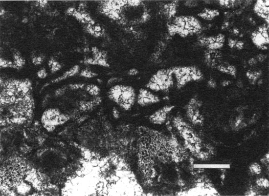
The crack patterns resulting from soil processes can be diagnostic of subaerial exposure (fig. 1) (Brewer, 1964; Freytet and Plaziat, 1982). Many such cracks curve around grains rather than cut across them because of the lack of extensive cementation in the sediment. Such short, curved cracks are called curved planes (Freytet and Plaziat, 1982) or circumgranular cracks (Swineford et al., 1958) (fig. 2). Desiccation and wetting also can produce discontinuous, parallel, planar cracks (fig. 3), which are commonly classified as fenestrae among geologists (Shinn, 1968, 1983) or as joint planes among soil micromorphologists (Brewer, 1964). More extensive cracking may produce a brecciated fabric in which particles can be fitted back together in puzzle-piece fashion (autoclastic breccia, skew planes) (fig. 4). Such a fabric indicates formation in place. Craze-plane fabrics (Brewer, 1964) can be produced by extensive brecciation and water infiltration, resulting in a fabric in which clasts can no longer be fitted back together (fig. 5) (Mazzullo and Birdwell, 1989; Wright, 1990). In argillaceous paleosols especially, the clasts (peds) produced by crack formation form diagnostic patterns, including platy, prismatic, columnar (fig. 6), and blocky structures (Retallack, 1988).
Figure 1--Idealized sketch of desiccation cracks in cross section. The scale can vary. Modified from Freytet and Plaziat (1982).
Figure 2--Photomicrograph of calcite spar filling complex system of "curved planes" or "circumgranular cracks" (plane-polarized light; Pennsylvanian Holder Formation, New Mexico). Other crack types are also present. The cracks result from desiccation and wetting. Scale bar is 250 µm.
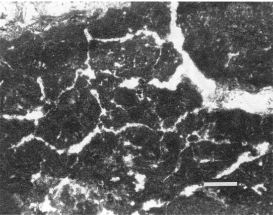
Figure 3--Photomicrograph of calcite spar filling discontinuous planar cracks that are subparallel to one another (plane-polarized light; Pennsylvanian Holder Formation, New Mexico). Such cracks, called joint planes, result from desiccation and wetting. Scale bar is 300 µm.
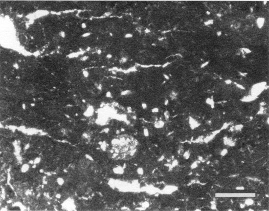
Figure 4--Photomicrograph of calcite spar filling discontinuous planar cracks that lack any preferred orientation (plane-polarized light; Pennsylvanian Holder Formation, New Mexico). Such skew planes produce an autoclastically brecciated fabric. Scale bar is 250 µm.
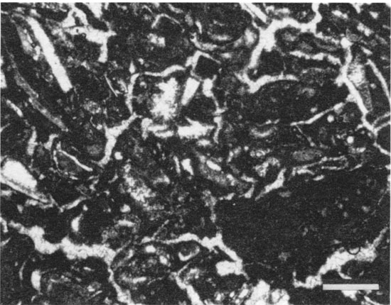
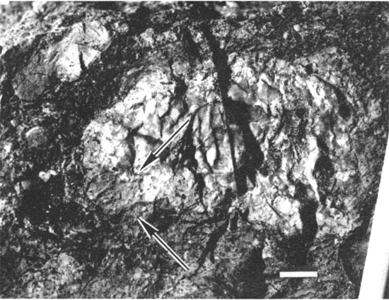
Figure 5--Weathered face of paleosol outcrop, Permian Laborcita Formation, New Mexico. Arrows indicate where extreme in-place crack formation has produced a "craze plane" fabric in which clasts are well separated by dark paleosol material. The rest of the outcrop face displays dark fillings of joint planes and skew planes. Scale bar is 2 cm.
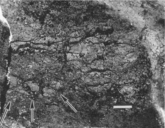
Figure 6--Outcrop of base of the Oskaloosa Shale Member, Deer Creek Limestone (Pennsylvanian), Kansas. Notice columnar structure produced by formation of paleosol. Scale bar is 5 cm.
Preserved upright plants provide strong evidence for paleosol formation, but preservation of plants in life position is unusual. More commonly, root structures (rhizoliths) are preserved as evidence of paleosols (Klappa, 1980b). In general, rhizoliths are identified as sinuous, cylindrical pores filled with internal sediment, later spar, or microcrystalline cement (fig. 7). Many rhizoliths are encrusted with multiple concretionary layers of microcrystalline calcite or calcite spar (rhizocretions) (fig. 8). Rhizoliths can be distinguished from most animal burrows by their tightly sinuous shapes, their downward or outward taper, their tendency to decrease in diameter at branches (fig. 9), and their ability to form integrated systems of root structures with thick, vertical taproots and shallow lateral roots (Klappa, 1980b).
Figure 7--Polished slab of paleosol in Sniabar limestone member (Pennsylvanian), Kansas. Dark, millimeter- and submillimeter-scale rhizoliths are abundant. Note that some form elongate features, some are branched, and others are reflected as aligned dark blebs resulting from intersection of sinuous cylindrical molds with the polished surface. Top centimeter or so consists of laminated crust. Horizontal joint planes are present in the lower left corner. Scale bar is 1 cm.
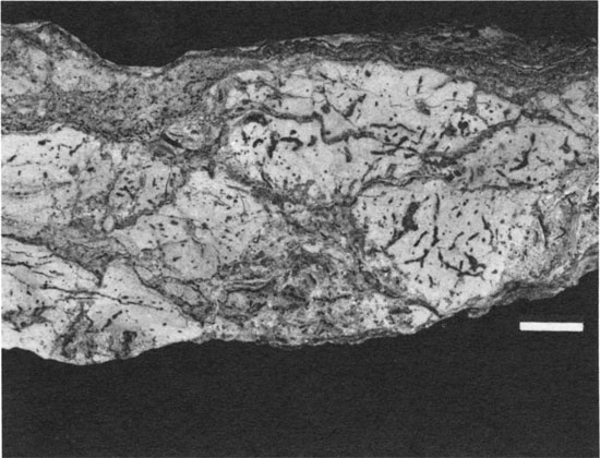
Figure 8--Photomicrograph of concentric encrustation around a root feature called a rhizocretion (plane-polarized light; Pennsylvanian Holder Formation, New Mexico). Scale bar is 250 µm.
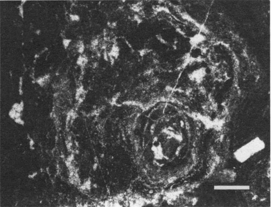
Figure 9--Outcrop of a Permian shale unit in Kansas. This unit has been penetrated by numerous roots. Arrow points to branched rhizolith in which the decrease in diameter at branches is apparent. Scale bar is 2 cm.
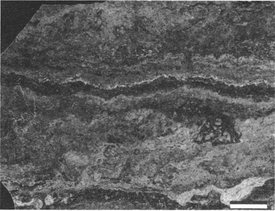
Laminated crusts composed of laminae of micrite and sparry calcite are common features of calcareous paleosols (fig. 10) (Read, 1976; Wright, 1989). These calcrete crusts may be concretionary around rhizoliths and may coat or replace particles along bedding, crack, or other surfaces of the host sediment. Many have a porous structure that contains common root molds.
Figure 10--Polished slab of laminated crust from a calcrete paleosol of the Pennsylvanian Holder Formation, New Mexico. Scale bar is 1 cm.
In carbonate paleosols grains may have multiple irregular coatings of micrite, microspar, or needle fiber calcite (fig. 11). Other coatings (cutans) that are common in paleosols are composed of clay minerals or oxides (Brewer, 1964).
Figure 11--Photomicrograph of grain coated by multiple, diffuse, discontinuous carbonate coatings that are intersected by circumgranular cracks (plane-polarized light; Pennsylvanian Holder Formation, New Mexico). Such discontinuous coatings are common features in paleosols. Scale bar is 50 µm.
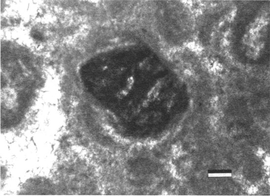
Sediment can be replaced extensively by micrite in soil environments (Kahle, 1977; James, 1972). Micritization in soils tends to destroy the original fabric of the host rock (fig. 12).
Figure 12--Field photograph of Permian Laborcita Formation, New Mexico, illustrating a chert cobble that has been partially altered by soil formation. Outer rind of cobble (between arrows) has been micritized. Scale bar is 1 cm.
In many calcareous paleosols calcite has precipitated as chalky, isolated, equidimensional or elongated nodules. Such "caliche nodules" can be recognized in ancient and modern calcareous soils (Esteban and Klappa, 1983).
Distinctive colors also have been used to identify paleosols. Reddish or orangish color, from precipitation of iron oxyhydroxides, is commonly used as an indication of soil formation. However, both colors may develop well after subaerial exposure from later oxidizing events, and color may be lost during later bleaching and reduction. Brown and black colors develop from preservation of sulfides and organic matter in paleosols. However, such dark colors should not be considered diagnostic of paleosol formation because they can form in other environments (Ward, 1978; Strasser, 1984; Shinn and Lidz, 1988).
Microscopic features associated with soil organic activity provide additional support for paleosol formation. Alveolar textures [e.g., Esteban (1974) and Goldstein (1988b); alveolar-septal structures of Wright (1986)] are microscopic structures that divide pores, forming irregular and cellular septae (figs. 13 and 14). Most of these structures result from calcification and encrustation of rootlet or fungal structures.
Figure 13--Idealized sketch of five different types of alveolar texture as viewed in thin section from the Pennsylvanian Holder Formation [after Goldstein (1988b)]. Black areas are micrite, shaded areas are marine bioclasts, and white areas are pore space. The types include (1) equidimensional cells surrounding root molds (R), (2) bridges composed of tangential needle fibers of calcite that occur within root molds, (3) alveolar texture sensu stricto, (4) regular coarse cells, and (5) irregular coarse cells.
Figure 14--Photomicrograph of dark micritic septae, which are a form of alveolar texture, a common microfabric of calcareous soils (plane-polarized light; Pennsylvanian Holder Formation, New Mexico). Scale bar is 150 µm.
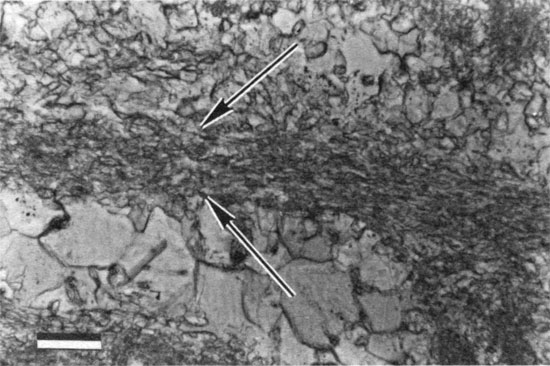
Tangential needle fibers of calcite (James, 1972) are subparallel microscopic fibers of calcite in which the long axes of the fibers are parallel to the surface they have encrusted or parallel to the long dimension of an alveolar structure (fig. 15). They most likely are a calcification of a fungal structure associated with soil organic processes (Ward, 1978; Wright, 1984; Callot et al., 1985).
Figure 15--Photomicrograph of tangential needle fibers of calcite [central band in photograph (between arrows)], a common structure preserved in calcareous paleosols (plane-polarized light; Pennsylvanian Holder Formation, New Mexico). Scale bar is 50 µm.
Microcodium (Gluck, 1912) is a more unusual soil-associated structure that is a millimeter- to submillimeter-sized aggregate of calcite prisms (fig. 16). It forms from either calcification of mycorhizzal associations (Klappa, 1978) or other soil-related processes (Freytet and Plaziat, 1982).
Figure 16--Photomicrograph of Pleistocene eolianite from Isla Contoy (crossed-polarized light). Notice individual blades of calcite that compose the internal structure of Microcodium. Photograph courtesy of William C. Ward. Scale bar is 75 gm.
Randomly distributed needle fibers of calcite are rare structures that are difficult to preserve, but they have been described in several ancient paleosols (Solomon and Walkden, 1985; Goldstein, 1988b).
Finding paleosol features provides the evidence necessary to infer an event of subaerial exposure. However, to use the features to constrain sea-level history, the timing of their development and the surface along which subaerial exposure occurred must be determined. It is well known that recent soil features can be superimposed on outcrops of ancient rocks. To disprove such recent superimposition on ancient rocks, paleosol features should be shown to be early in the diagenetic sequence and they should predate diagenetic features, such as stylolites and through-going fracture fills. Moreover, a stratigraphic horizon with paleosol features may result from subaerial exposure of that horizon or subaerial exposure of units higher in the stratigraphic sequence. For instance, paleosol-like features can develop at the water table or along permeability discontinuities well below the surface of subaerial exposure (Semeniuk and Meagher, 1981; Semeniuk and Searle, 1985) and thus can mimic surfaces of subaerial exposure. For example, if rhizoliths originating from an overlying horizon extend downward to a lower altered horizon, the lower horizon may not represent a discrete surface of subaerial exposure; it could simply represent some of the paleosol alteration associated with a surface of subaerial exposure higher in the stratigraphic sequence. To distinguish lower altered horizons from the actual surfaces of subaerial exposure, field relationships must demonstrate the presence or absence of a link between the altered horizon and the overlying paleosol horizons and must determine whether the altered horizon parallels or cuts across stratigraphic surfaces.
An example of the utility of paleosols in constraining the history of change in sea level is from the Pennsylvanian (Virgilian) Holder Formation of southern New Mexico (Goldstein, 1988b), which consists of approximately 20 carbonate-siliciclastic cycles deposited on the edge of the Pedernal uplift (Wilson, 1967) (fig. 17). The limestone units in the cycles show evidence of shallowing upward but for the most part appear to have been deposited entirely in the subtidal realm. For many Holder cycles, paleosols are developed within the uppermost meter of the carbonate units (figs. 18 and 19). Rhizoliths, tangential needle fibers of calcite, alveolar texture, irregular coatings on grains, micritized grains, cracks from desiccation, and laminated crusts provide good evidence for paleosols and thus indicate repeated subaerial exposure during deposition of the Holder Formation. Because most of the paleosols are developed on subtidal carbonate rocks, simple aggradation into the subaerial realm could not have caused subaerial exposure; a fall in sea level or tectonic uplift is required. Some paleosols are laterally continuous and can be traced from the shelf to more basinal positions (fig. 20). Their characteristics change laterally in response to different timing of exposure and different paleohydrogeologic setting (Goldstein, 198 8b) (fig. 21). For one surface onlapping relationships of overlying beds and original topography on bioherms reflect 30-50 m (100-160 ft) of paleotopography on marine rocks capped by a single paleosol, indicating a relative fall in sea level of at least 30-50 m (100-160 ft) (Goldstein, 1988b).
Figure 17--Paleogeographic reconstruction of Holder Formation study area. The Holder outcrop was studied on the edge of the Sacramento shelf between the Pedernal uplift and the Orogrande basin [after Meyer (1966)].
Figure 18--Idealized shelf cycle for the Holder Formation. Modified from Wilson (1967).
Figure 19--Idealized cross sections of typical paleosols developed on the tops of Holder Formation limestones. The features sketched are those that would be observed in the field [after Goldstein (1988b)].
Figure 20--Cross section constructed from four stratigraphic sections in the Holder Formation. Surfaces A through F are used for correlation. Correlations with solid lines indicate high confidence; correlations with dashed lines indicate fair confidence; correlations with dotted lines are inferred. H/B is the Holder Formation-Beeman Formation contact. Lower parts of section 1 are basinal; lower parts of section 2 are on the shelf edge; lower parts of section 3 are on the shelf crest; lower parts of section 4 are lagoonal. Between sections 1 and 2, notice the shelfward convergence of surfaces A, B, and C. Siliciclastic strata in the basin onlap the slope to reflect significant paleotopography.
Figure 21--Model that integrates lateral variation of paleosol from a surface of subaerial exposure in the Holder Formation [after Goldstein (1988b)]. East of the shelf edge, the paleosol is well developed and contains abundant rhizoliths and laminated crusts. Evidence in paleosols suggests that the water table approached the paleosol surface at times. West of the shelf edge, the paleosol is only poorly developed and breccias and leached grains are common. The hydrologic model could explain this lateral change.
Dissolution of limestone can occur during ancient subaerial exposure of carbonate strata. Identification of such paleokarst formation yields valuable evidence for subaerial exposure and provides a further means to determine minimum relative falls in sea level. Dissolution of carbonate sediment is to be expected in strata subjected to chemically corrosive ground water charged with atmospheric or soil CO2 or mixtures of two different ground waters (Thrailkill, 1968; Back et al., 1984; Ford et al., 1988). The key for developing the paleokarst method of tracing sea-level change is, first, the recognition of karst and, second, the establishment of the timing of its formation relative to a particular stratigraphic surface of subaerial exposure. Paleokarst must be related to the surface of subaerial exposure to determine magnitude of sea-level fall through tracing the depth of vadose diagenesis or paleotopography on the exposure surface.
Karst cavities can have any shape (Palmer, 1991) but are still easy to recognize. They generally cut across the rock fabric to some degree. The walls tend to be smooth from the solution process. Void walls do not fit together in puzzle-piece fashion, as simple dilational voids would. Karst limestones commonly produce a rubbly outcrop, resulting from smaller cavities that dissect the host limestone.
Some karst landforms develop at the surface of subaerial exposure or just below a cover of soil. The dissolution at and near the subaerial surface sculpts the surface of the carbonate rock to produce runnel, pinnacle, trough, pit, and other forms. Given adequate outcrops, such forms can be useful in identifying ancient surfaces of subaerial exposure (Esteban and Klappa, 1983; Ford et al., 1988).
In other settings near-surface karst processes develop gradational contacts between an underlying bed of limestone and an overlying bed of reddish siliciclastic material. The limestone may contain small interconnected pockets and vugs filled with the siliciclastic material, much of which is presumed to be the residue of limestone dissolution. The dissolution of host limestone would have occurred near the subaerial surface as part of a soil profile and thus represents subaerial exposure and dissolution (terra rossa paleosol) before deposition of the overlying stratigraphic unit (Goldhammer and Elmore, 1984).
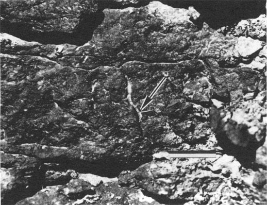
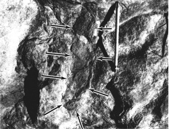
In some settings karst is related to near-surface infiltration and downward percolation of meteoric water through the vadose zone. Such vadose karstification can cause near-vertical solutional voids that extend downward from or just below the subaerial surface. The vertical, pipe, or stair-step shape of these caves generally allows them to be distinguished from caves formed in the phreatic zone (fig. 22) (Wright, 1982; Esteban and Klappa, 1983; Ford et al., 1988). These large voids may remain open or be filled with speleothems, the sediment residue of dissolution, paleosol material, or sediment of the overlying bed. For quantifying minimum relative fall in sea level, ancient examples of such karst would be easy to relate to a particular surface of subaerial exposure, because the vertical voids would extend upward to or just below the stratigraphic surface at which subaerial exposure occurred. Moreover, because the vertical voids formed mostly in the vadose zone, the depth to which they penetrate can be used as further quantification of minimum relative fall in sea level.
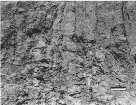
Figure 22--Outcrop of the Pennsylvanian Holder Formation, New Mexico. Arrows point to margin of vertical solution pipe developed from karstification in the vadose zone. Pencil is 17.5 cm long.
Other karstification produces cavities in which age and origin are unclear, because they do not show an easily understood relationship to a surface of subaerial exposure. For instance, one might find karst cavities within ancient limestones that formed hundreds of meters beneath the surface of subaerial exposure. Because of the complex variables that control karst formation, the shape and position of the solution cavities may yield no clues to their timing or environment of formation. Moreover, some karst cavities develop along permeability or lithologic discontinuities so that their relationship to a stratigraphic surface mimics one of the aforementioned subaerial-surface-related examples (Wright, 1982; Palmer, 1991). Furthermore, karstification at the water table or a laterally continuous mixing zone could confine karst to a stratigraphic horizon to mimic subaerial-surface-related karst.
There are some other simple criteria that allow paleokarst developed at or just below the subaerial surface (surface paleokarst) to be distinguished from karst cavities that developed well below the subaerial surface [as summarized by Wright (1982)]. Surface paleokarst might be overlain by paleosol or terrestrial sediment; it might be associated with features indicative of the vadose zone; it might be truncated by overlying beds; overlying beds should not contain solutional voids that connect to a higher surface of subaerial exposure, and overlying beds should not display evidence of collapse into the cavities.
In settings in which the cavities show no clear temporal relationship to a surface of subaerial exposure or in which the cavities cannot be demonstrated to have formed in the vadose zone, it may be difficult to interpret minimum relative falls in sea level. To interpret relative falls in such settings, we must determine the age of the cavities relative to a stratigraphic surface. Commonly, karst voids contain stratified fillings of insoluble residue, paleosol, later sediment that has filled in from above, fragments of host limestone, and speleothems (fig. 23). The age of infilling can be determined biostratigraphically through examination of the nonreworked fossils contained in the cavity fillings. Careful biostratigraphic and petrographic study might be necessary to distinguish reworked from nonreworked fossils. Further dating can be accomplished by comparing karst-filling lithologies to lithologies higher in the stratigraphic sequence; if a lithologic match is produced, the cavity predates deposition of a particular stratigraphic unit and thus may help in determining the timing and position of the surface of subaerial exposure. The surface of subaerial exposure can be further constrained through mapping of paleokarst networks and by relating the networks to a stratigraphic surface up-section (Craig, 1988). More complicated petrographic (cement stratigraphy) and geochemical (stable isotopes) applications are also useful in determining the age of karst formation and thus the timing and extent of subaerial exposure (Meyers, 1974, 1988; Goldstein, 1990).
Figure 23--Field sketch of karst pocket in the Mississippian Lake Valley Limestone of southern New Mexico [after Goldstein (1990)]. Note the smooth, rounded walls and closely associated shaly filling and speleothems.
Stable isotopic analyses of whole-rock and microcomponent samples commonly are used to identify ancient surfaces of subaerial exposure. The whole-rock method, developed by Allan and Matthews (1982), predicted that stabilization of marine carbonate sediment during subaerial exposure could produce a relatively negative carbon signature from plant-derived soil-gas CO2, a relatively positive oxygen signature from evaporation, and an overall shift in oxygen isotopic composition because of different diagenetic histories across a buried surface of subaerial exposure (fig. 24). Finding two or more such signatures at an ancient surface was considered sufficient (by Allan and Matthews) to identify an event of subaerial exposure. This technique has value in identifying subtle surfaces of subaerial exposure that otherwise would have been missed (Major and Matthews, 1983), in verifying other evidence for exposure (Allan and Matthews, 1982), and in identifying surfaces for exploratory purposes.
Figure 24--Schematic diagram of potentially useful patterns of δ18O and δ13C across an ancient surface of subaerial exposure [modified from Allan and Matthews (1982)].
There are many variables that introduce ambiguity into interpreting whole-rock isotope trends, and therefore corroborating evidence of subaerial exposure is desirable. If significant mineral stabilization or recrystallization does not take place during subaerial exposure, then the predicted isotope trends may not develop. The amount of recrystallization or mineral stabilization during subaerial exposure versus the amount of preserved marine carbonate or later diagenetic phase ultimately will affect the isotopic composition of the whole rock. Moreover, the carbon isotopic composition developed in an ancient limestone that has been subaerially exposed might be related to the isotopic composition and amount of decomposing organic matter, fractionation to more positive values during carbon dioxide degassing, the contribution of sediment carbon, and the contribution of atmospheric carbon (Fomaca-Rinaldi et al., 1968; Hendy, 1971; Cerling et al., 1989). Oxygen isotopic trends might be related to the isotopic composition of meteoric water, temperature, relative humidity, evaporation, kinetic factors, and the degree of preservation of the original sediment signal (Fantidis and Ehhalt, 1970; Salomons et al., 1978; Lohmann, 1982; Meyers and Swart, 1989). Finally, subsequent diagenetic events can overprint an isotopic signal related to the exposure event.
A study from the Pennsylvanian Holder Formation of southern New Mexico (Goldstein, 1991b) illustrates the utility and potential ambiguity of the isotopic technique for identification of surfaces of subaerial exposure. Whole-rock samples across paleosol-capped cycles and microcomponent data from paleosol-precipitated phases demonstrate the nature of the isotopic signals. The stratigraphy of the Holder Formation in the study area (Toomey et al., 1977) consists of several shoaling-upward carbonate cycles. The tops of two of the cycles contain diagnostic paleosol fabrics, such as laminated crust, rhizoliths, alveolar texture, vadose-zone cement, autoclastic breccia, and many other paleosol fabrics (fig. 25).
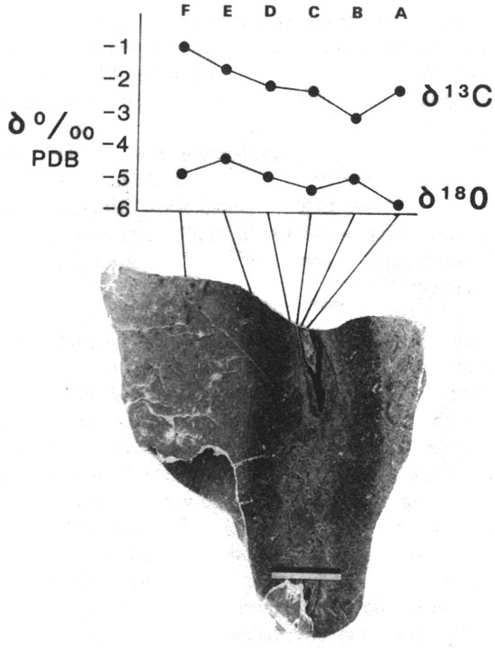
Figure 25--Stable isotopic composition of soil-formed microcomponent and whole-rock samples relative to stratigraphic position of two surfaces of subaerial exposure in the Holder Formation. Letters A through J designate stratigraphic units [detailed discussion by Goldstein (1991b)].
Soil-formed microcomponents analyzed for their isotopic composition include thin layers of vadose-zone cement (ribbon spar), laminated crusts, and rhizoliths. The most obvious feature of the microcomponent isotopic compositions is their variability (figs. 25 and 26). For instance, microcomponent data along a narrow stratigraphic interval (top of unit F) show wide variability in both carbon (about 3‰) and oxygen (about 3‰) isotopic composition. Moreover, the carbon signal can be spatially related to the distribution of organic matter in the soil. Sample traverses taken adjacent to rhizoliths show that the isotopically lightest signatures develop close to rhizolith cores and get progressively more positive outward (fig. 27). Therefore the isotopic signatures developed during subaerial exposure appear to be spatially or temporally heterogeneous.
Figure 26--Isotopic composition of soil-formed microcomponents from stratigraphic units F and H (fig. 25). Shaded field approximates the position of a meteoric calcite line at about -5.5‰ δ18O. Divergence to the right can be explained by a combination of temporal variation, such as seasonal changes, evaporation, CO2 degassing, or variations in the ratios of components mixed in the system.
Figure 27--Isotopic data relative to the position of a concretionary rhizolith from unit F (fig. 25). Notice the progressive decrease in δ13C toward center of rhizolith (excluding late sparry calcite-rich core). (A) Rhizolith core; (B, C) concretionary coatings; (D) totally altered and replaced marine sediment; (E) partially replaced marine sediment; (F) marine sediment cemented with soil-precipitated calcite. Scale bar is 2 cm.
The overall variability in isotopic composition of soil-formed microcomponents suggests that compositions diverge away from a "meteoric calcite line" (fig. 26) of variable δ13C and consistent δ18O (Lohmann, 1988). Such divergence is most easily explained by a combination of evaporation and carbon dioxide degassing, but variations in organic flux, rock carbon input, atmospheric carbon input, and climatic variations are all possibilities. The more negative carbon isotopic values provide strong support for subaerial exposure, but more positive values appear to be preserved along with them.
Comparison of whole-rock isotopic compositions to microcomponent data may or may not show significant deviations. For instance, the top of unit F (fig. 25) shows a negative carbon shift in both whole-rock and microcomponent data. On the other hand, the microcomponents on the top of unit H (fig. 25) yield a significantly negative carbon shift, but no negative carbon shift is observed in whole-rock data at the same horizon. At this horizon the whole-rock samples contain only small amounts of the soil-formed microcomponents. This indicates that whole-rock isotopic signatures are not retained through stabilization of the host sediment during exposure. Apparently, the whole-rock signature is controlled by the amount of soil-precipitated phase that is present. High concentrations of soil phase yield the whole-rock shift, and low concentrations do not. This has important implications for use of the whole-rock isotope technique. In paleosols a heterogeneous distribution of rhizoliths and laminated crusts formed at or well below a subaerial surface (even at the water table) is well known. Such a distribution could yield vertically and laterally variable whole-rock isotopic signals of questionable relationship to the subaerial exposure surface. The isotopic signals would trace the distribution of soil-precipitated phases rather than the distribution of the subaerial surface.
Whole-rock trends toward more positive δ18O values are largely absent in the Holder Formation samples (fig. 25). Although microcomponent data suggest that minor evaporation took place, no heavy oxygen signal is recorded in whole-rock samples near surfaces of subaerial exposure. Apparently, this is caused by the lack of a significant volume of soil microcomponents formed during evaporation. Whole-rock oxygen shifts are also absent across the surfaces, suggesting that these closely spaced cycles have experienced similar diagenetic histories.
Although the whole-rock method of isotopic analysis probably would not have been sufficiently unambiguous to infer subaerial exposure at these surfaces in the Holder Formation, the observed whole-rock compositions at exposure surface 1 would have raised suspicion that further investigation was necessary. Furthermore, the relatively negative carbon signatures preserved in the soil-formed microcomponents are useful for providing further evidence of subaerial exposure.
When carbonate strata are subjected to subaerial exposure, infiltration of meteoric water may result in low-magnesium calcite cementation (Bathurst, 1975; Longman, 1980). Low-magnesium calcite cement can provide a record of the history of subaerial exposure, which in turn allows interpretation of history of sea-level fall.
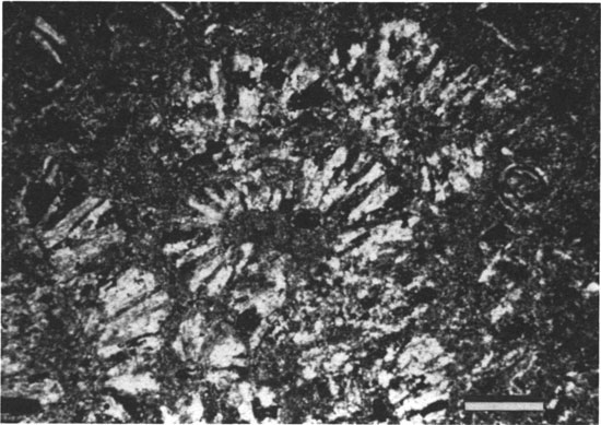
Obvious indicators of subaerial exposure are calcite cements that preserve evidence of cementation in the vadose zone. The vadose zone may extend well below a surface of subaerial exposure, so care must be taken when relating the vadose cements to the exposure surface. Moreover, because it is unlikely that the vadose zone extends below sea level, the depth below an exposure surface to which vadose-zone cements extend can be used as a constraint on estimating the minimum amount of fall in sea level. Calcite cement with pendant fabrics (fig. 28) (Purser, 1969; Grover and Read, 1978), preferred growth near grain contacts (Meyers, 1974), or meniscus fabrics (fig. 29) (Dunham, 1971) provide good evidence of cementation in the vadose zone.
Figure 28--Photomicrograph of pendant cement that is apparent because of concentrations of fluid inclusions (plane-polarized light). Inclusion-rich cement hangs beneath crinoid fragment. Terminations are smooth and drop shaped; growth zones thin and pinch out upward around side of crinoid fragment. Arrow points to outermost band of inclusions outlining drop-shaped termination. In Mississippian Lake Valley Limestone, New Mexico. Scale bar is 250 µm.
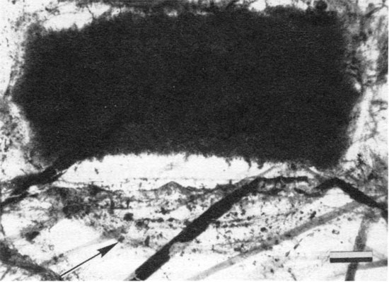
Figure 29--Meniscus cement linking ooid grains from Joulter's Cay (Halley and Harris, 1979) (plane-polarized light). Scale bar is 100 µm.
Cement stratigraphy of compositional growth banding in calcite (Meyers, 1974), as revealed by staining, cathodoluminescence, ultraviolet fluorescence, back-scattered electron imaging, and X-ray mapping, can provide a more subtle record of subaerial exposure. Vertical changes in the pattern of cement zonation may be caused by cementation associated with buried surfaces of subaerial exposure. Cement zones that precipitated from meteoric water recharged during the exposure event should not be traceable above the exposure surface, but later events should be traceable across it (Meyers, 1974; Walkden, 1987; Goldstein, 1988a; Horbury and Adams, 1989). The position of the ancient exposure surface could be identified by locating the stratigraphic position at which cement zones resulting from an exposure event pinch out upward (fig. 30).
Figure 30--Hypothetical correlation of cement zones taken from samples vertically in a stratigraphic section. Zonation is somewhat idealized. Between samples E and F, the earliest zones pinch out upward, recording an event of cementation associated with subaerial exposure. Downward pinchouts of cement zones are related to hydrogeologic and geochemical factors of the freshwater aquifer.
Cross-cutting relationships with features formed during subaerial exposure (see foregoing discussions on paleosols and paleokarst) are essential to show that cement zones are related to subaerial exposure events (Goldstein, 1991 a). Merely tracing cathodoluminescent zones relative to stratigraphic surfaces can be misleading because of the complexities of paleoaquifer chemistry and flow. For instance, lateral and vertical changes in cathodoluminescent pattern may be related to such variables as localized sources of iron and manganese or change in redox potential related to one of many aquifer parameters (e.g., rate of fluid flow relative to organic reactions) (Grover and Read, 1983; Dorobek, 1987; Searl, 1988). The cross-cutting relationships provide an adequate means of distinguishing those changes in cement zonation related to exposure events from those related to compartmentalized flow in the subsurface or those related to stratigraphically localized geochemical facies in the subsurface. Further determination of the origin of changes in cement zonation can be aided by geochemical tracers such as stable isotopes and fluid inclusions.
In some rocks complex pore fluid history has produced variable cement zonation that has made lateral and vertical tracing of cement zones difficult (Searl, 1988). In other systems zonation patterns are not observable or are non-unique so that identification of surfaces of subaerial exposure is difficult. In some settings subaerial exposure may not result in significant calcite cementation. For these situations cement stratigraphy is not an appropriate method for locating ancient surfaces of subaerial exposure.
In the Holder Formation limestones cross-cutting relationships with paleosol features, fissure fillings, early fractures, and clast boundaries in intraformational conglomerates relate calcite cements to events of subaerial exposure (Goldstein, 1988a). Some calcite zones both predate and postdate the paleosol or paleokarst features of a particular horizon, and thus the cement zones are shown to have precipitated during subaerial exposure. Those cement zones that precipitated during the intraformational events of subaerial exposure are early in the paragenetic sequence and predate compaction features and tectonic fractures. Vertical tracing of different sequences of those intraformational cement zones reflect at least 15 events of subaerial exposure during which the limestones' underlying surfaces of subaerial exposure were cemented with calcite (fig. 31). In general, these cement zones cannot be traced downward through thick shales and cemented limestones. Apparently, they acted as aquitards during exposure and prevented cementation in underlying strata. The early cements are best developed in a shelf-crest setting and tend to become less abundant in a basinal or lagoonal direction (figs. 20 and 31) (Goldstein, 1988a). Thus, locating surfaces of subaerial exposure from cement stratigraphy should be most applicable in shelf settings. Lateral tracing of one of the surfaces exhibiting changes in cement zonation reveals that sea level must have dropped 30-50 m (100-160 ft) (fig. 20).
Figure 31--Cement stratigraphy for four stratigraphic sections in the Holder Formation. Shaded area refers to late cements; white area with lines of internal correlation refers to quantity and distribution of early cement associated with surfaces of subaerial exposure. Refer to fig. 20 for stratigraphy. In general, the lower half of section 1 can be considered basinal, the lower half of section 2 can be considered to have been in a shelf-edge setting, the lower half of section 3 can be considered to have been in a shelf-crest setting, and the lower half of section 4 can be considered to have been in a lagoonal setting. Early cements are developed best on shelf localities. Each "E" denotes the position of a surface of subaerial exposure and the line underneath it reflects the distance below the surface through which its associated cement zones can be traced.
Many of the siliciclastic sandstone units in the Holder Formation contain only small amounts of the early meteoric calcite. Subaerial exposure surfaces that exist in the siliciclastic units generally have not resulted in calcite cementation of those siliciclastics. However, sandstone units that directly underlie the limestones that are capped by surfaces of subaerial exposure may contain early meteoric calcite cement that correlates with the cement zones of the directly overlying limestone. For such a sandstone point-count data from six samples show that the meteoric calcite is developed best in those sandstones that contain a high content of calcareous lithic fragments and bioclasts (fig. 32). This reconnaissance work suggests that development of early meteoric calcite cement in sandstone was compositionally controlled and that subaerial exposure of limestone appears to be required for development of meteoric calcite cement in underlying strata (Bowman, 1987). Therefore cement stratigraphy of meteoric calcite cement should be applicable to sandstones only in relatively special situations.
Figure 32--Percentage of early cement (expressed in percentage of meteoric calcite in occluded porosity) versus percentage of depositional carbonate (percentage of the depositional grains that are carbonate as opposed to siliciclastic in composition). Data are from point counts of sandstones and limestones closely underlying a surface of subaerial exposure on a limestone (Holder Formation). These reconnaissance data suggest that the amount of early cement increases with increasing carbonate grains in sandstones (Bowman, 1987).
Calcite cements of the Lansing-Kansas City Groups The Pennsylvanian (Missourian) limestones of the Lansing-Kansas City Groups of northwestern Kansas and southwestern Nebraska (fig. 33) show that the cement stratigraphic technique is not universally applicable for locating surfaces of subaerial exposure. These units consist of carbonate-siliciclastic cyclic strata that show evidence of repetitive subaerial exposure (Watney, 1980). They were deposited within a relatively paleotopographically low area between the Central Kansas uplift and the Las Animas arch. Despite cyclic subaerial exposure, cement stratigraphic patterns have not proven useful in reflecting the events of subaerial exposure. Most of the cathodoluminescent cement zones postdate compaction. This observation suggests that calcite cements early in the paragenetic sequence postdate at least some burial and may be unrelated to cycle-capping subaerial exposure. The sequence of cathodoluminescent zones is traceable across multiple cycles (fig. 34). Fluid inclusion data indicate calcite cementation from low-temperature brines rather than from freshwater (fig. 35) (Anderson, 1989). Such evidence suggests that calcite cementation took place from brines that refluxed through the Pennsylvanian section during deposition of Permian evaporites.
Figure 33--Location of cores from the Lansing-Kansas City Groups [after Anderson (1989)].
Figure 34--Vertical distribution of cement zones in the Lansing-Kansas City Groups. LS designates limestone reservoir units that are presented in stratigraphic sequence. Bar patterns identify packages of cement zones that occur in the numbered order. The length of each bar corresponds to the percentage of the pore space (that existed before cementation) that is now occluded by the cement. Percentages are averages for each stratigraphic interval and are based on visual estimates from 136 thin sections. No relationship to stratigraphic position is observed at this level of detail [after Anderson (1989)].
Figure 35--Fluid inclusion data from early calcite of the Lansing-Kansas City Groups. Tm,ice = final melting temperature of ice. One-phase all-liquid inclusions indicate cement precipitation at less than 40-50°C followed by reequilibration to make some two-phase fluid inclusions. One-phase inclusions preserve concentrated brines with large freezing point depressions. Therefore the cement precipitated from a low-temperature brine [after Anderson (1989)].
Because the setting of the Lansing-Kansas City Groups was in a relatively paleotopographic ally low area, its setting probably was not conducive to development of abundant meteoric calcite cement during events of subaerial exposure (as observed in the Holder Formation). Thus cement stratigraphy in this paleotopographically low setting is not closely related to sea-level history.
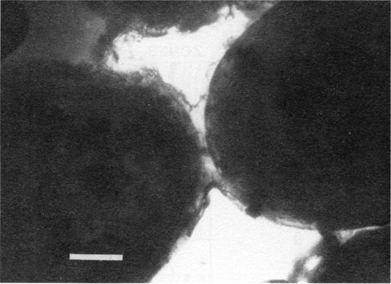
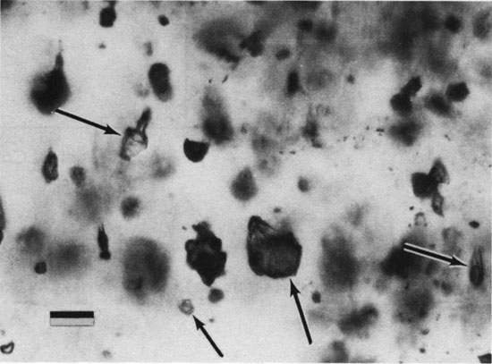
During precipitation of calcite from a fluid, some of the fluid can be trapped within the growing crystal. These fluid inclusions can provide useful information on the location of the vadose zone and thus can help to constrain the amount of fall in sea level. The vadose zone is a two-phase system in which both vadose atmosphere and water are present in the pores. Cements that grow in the vadose zone reflect this system because they include all-liquid, all-gas, and two-phase inclusions with highly variable ratios of gas to liquid (fig. 36) (Goldstein, 1986). The pressure within these inclusions is 1 atm. Alternatively, fluid inclusions trapped in the low-temperature phreatic zone are all liquid; fluid inclusions trapped from high-temperature fluids have two phases with small bubbles and with consistent vapor to liquid ratios, and fluid inclusions that have been naturally overheated may develop small bubbles in some inclusions because of volume increase (Goldstein, 1986, 1990).
Figure 36--Photomicrograph of fluid inclusions trapped in calcite that precipitated in the vadose zone (plane-polarized light). Notice highly variable ratios of vapor to liquid. Arrows point to fluid inclusions that have different ratios of vapor to liquid. Speleothem from Carlsbad Caverns, New Mexico. Scale bar is 25 µm.
Therefore fluid inclusions trapped in the vadose zone remain distinctive by virtue of their combination of one-phase inclusions and two-phase inclusions with highly variable ratios of vapor to liquid. Burial heating and laboratory heating of such populations can cause reequilibration of some of the inclusions. Most reequilibration affects originally one-phase all-liquid inclusions by increasing their volume and causing nucleation of small vapor bubbles at room temperature. Thus the distinctive variability in the vapor-liquid ratio of the vadose inclusion population is preserved in rocks that have been naturally heated. Populations of fluid inclusions with these characteristics can be used to trace the location of ancient vadose zones (Goldstein, 1990).
The Miocene marine carbonate strata of southeastern Spain consist of depositional sequences that are separated by stratigraphic breaks (fig. 37), some of which are of ambiguous origin (Franseen, 1989). The stratigraphic breaks can be traced laterally. In one area, Mesa Roldan (fig. 38), an ambiguous break can be shown to have at least 50-55 m (160-180 ft) of original depositional relief preserved (Esteban and Giner, 1980; Franseen, 1989). If this ambiguous break could be demonstrated to be a surface of subaerial exposure, then a minimum drop in sea level of 50-55 m (160-180 ft) could be demonstrated.
Recently, Goldstein et al. (1990) used the distribution of fluid inclusions in calcite cement to demonstrate a vadose-zone signal associated with this stratigraphic break. Limestones within one depositional sequence (DS2, fig. 37) contain common sparry calcite cement. Yet the base of the overlying sequence (DS3, fig. 37) is a porous dolomite that lacks calcite cement. Such a distribution suggests that the calcite cement of DS2 predates deposition of DS3.
Figure 37--Depositional sequences (DS), terminal carbonate complex (TCC), and megabreccias (MB) [modified from Franseen (1989)] in relation to carbonate strata of Mesa Roldan [modified from Esteban and Giner (1980); after Goldstein et al. (1990)].
Figure 38--Location diagram for Mesa Roldan area of southeastern Spain [after Goldstein et al. (1990)].
Petrographic examination of the calcite in DS2 reveals fluid inclusions that consist of all liquid, all gas, or gas and liquid with highly variable phase ratios. Such distributions are highly indicative of cementation in a two-phase diagenetic system such as the vadose zone. Furthermore, by crushing the calcite crystals between two glass plates to open the inclusions while immersed in a liquid at 1-atm pressure, the pressure within the inclusions is shown to be approximately 1 atm. This offers further support for a vadose-zone interpretation.
Ice melting temperatures (Tm,ice) were determined for the inclusions (fig. 39). Most inclusions yielded Tm,ice of 0.0°C, indicating a freshwater composition. Others yielded Tm,ice as low as -0.7°C, indicating brackish fluids as saline as 12 wt % NaCl equivalent (Potter et al., 1978).
Figure 39--Frequency histogram of freezing point depression for fluid inclusions in Miocene strata, Mesa Roldan. Most inclusions contain freshwater, whereas some inclusions are brackish and have salinities as high as 1.2 wt % NaCl equivalent (Potter et al., 1978).
The inclusion data strongly support cementation from the vadose zone. The distribution of cements suggests cementation before deposition of DS3. Therefore the ambiguous break between DS2 and DS3 represents an event of subaerial exposure. Because the surface covers depositional relief of at least 50-55 m (160-180 ft), a relative sea-level fall of at least that amount can be interpreted for the boundary between the two sequences. Brackish water in some of the inclusions may even suggest proximity to the ancient shoreline during the event of subaerial exposure.
The identification of subaerial diagenesis can provide a useful record of the history and magnitude of sea-level change. Ancient surfaces of subaerial exposure are best integrated with other determinations of paleotopography and depth of vadose diagenesis to provide a quantitative record of minimum relative falls in sea-level. The following diagenetic methods are useful for determining this history.
This work benefited greatly from discussions with Lloyd C. Pray, Gwendolyn Macpherson, Robert Buddemeier, Evan Franseen, and T. James Reynolds. Steve Dorobek and Bill Meyers provided helpful reviews that improved the manuscript. Funded in part by the University of Kansas, Geology Associates Fund and General Research allocation 3809XO-0038.
Allan, J. R., and Matthews, R. K., 1982, Isotope signatures associated with early meteoric diagenesis: Sedimentology, v. 29, p. 797-818
Anderson, J. E., 1989, Diagenesis of the Lansing and Kansas City Groups (Upper Pennsylvanian), northwestern Kansas and southwestern Nebraska: M.S. thesis, University of Kansas, Lawrence, 259 p.
Back, W., Hanshaw, B. B., and Van Driel, J. N., 1984, Role of ground water in shaping the eastern coastline of the Yucatan Peninsula, Mexico; in, Groundwater as a Geomorphic Agent, R. G. LeFleur, ed.: Allen and Unwin, Inc., Boston, Massachusetts, p. 281-293
Bathurst, R. G. C., 1975, Carbonate sediments and their diagenesis: Developments in Sedimentology 12, Elsevier, New York, 658 p.
Bowman, M. W., 1987, Sandstone diagenesis in an interbedded carbonate-siliciclastic sequence, Virgilian Holder Formation, New Mexico: M.S. thesis, University of Kansas, Lawrence, 166 p.
Brewer, R., 1964, Fabric and mineral analysis of soils: Wiley & Sons, New York, 470 p.
Callott, G., Guyon, A., and Mousain, D., 1985, Interrelations entre aiguilles de calcite et hyphes myceliens: Agronomie, v. 5, p. 209-216
Cerling, T. E., Quade, J., Wang, Y., and Bowman, J. R., 1989, Carbon isotopes in soils and paleosols as ecology and paleoecology indicators: Nature, v. 341, p. 138-139
Craig, D. H., 1988, Caves and other features of Permian karst in San Andres Dolomite, Yates field reservoir, west Texas; in, Paleokarst, N. P. James and P. W. Choquette, eds.: Springer-Verlag, New York, p. 342-362
Devaney, K. A., Wilkinson, B. H., and Van der Voo, R., 1986, Deposition and compaction of carbonate clinothems--the Silurian Pipe Creek Junior complex of east-central Indiana: Geological Society of America, Bulletin, v. 97, p. 1,367-1,381
Dorobek, S. L., 1987, Petrography, geochemistry, and origin of burial diagenetic facies, Siluro-Devonian Helderberg Group (carbonate rocks), central Appalachians: American Association of Petroleum Geologists, Bulletin, v. 7, no. 5, p. 492-514
Dunham, R. J., 1971, Meniscus cement; in, Carbonate Cements, O. P. Bricker, ed.: American Association of Petroleum Geologists, Studies in Geology 19, Johns Hopkins University Press, Baltimore, Maryland, p. 297-300
Enos, P., and Perkins, R. D., 1979, Evolution of Florida Bay from island stratigraphy: Geological Society of America, Bulletin, v. 90, p. 59-83
Esteban, M., 1974, Caliche textures and Microcodium: Bollettino della Societa Geologica Italiana, v. 92 (supp.), p. 105-125
Esteban, M., and Giner, J., 1980, Messinian coral reefs and erosion surfaces in Cabo de Gata (Almeria, SE Spain): Acta Geologica Hispanica, v. 115, p. 97-104
Esteban, M., and Klappa, C. F., 1983, Subaerial exposure environment; in, Carbonate Depositional Environments, P. A. Scholle, D. G. Bebout, and C. H. Moore, eds.: American Association of Petroleum Geologists, Memoir 33, p. 1-54
Fantidis, J., and Ehhalt, D. H., 1970, Variations of the carbon and oxygen composition in stalagmites and stalactites--evidence of nonequilibrium isotopic fractionation: Earth and Planetary Science Letters, v. 10, p. 136-144
Ford, D. C., Palmer, A. N., and White, W. B., 1988, Landform development--karst; in, The Geology of North America--Hydrogeology, W. Back, J. S. Rosenshein, and P. R. Seaber, eds.: Geological Society of America, v. O-2, p. 401-412
Fomaca-Rinaldi, G., Panichi, C., and Tongiorgio, E., 1968, Some causes of the variation of the isotopic composition of carbon and oxygen in cave concretions: Earth and Planetary Science Letters, v. 4, p. 321-324
Franseen, E. K., 1989, Depositional sequences and correlation of Middle to Upper Miocene carbonate complexes, Las Negras area, southeastern Spain: Ph.D. dissertation, University of Wisconsin, Madison, 374 p.
Freytet, P., and Plaziat, J. C., 1982, Continental carbonate sedimentation and pedogenesis--Late Cretaceous and Early Tertiary of southern France, B. H. Purser, ed.: Contributions to Sedimentology 12, Schweizertische Verlagsbuchhandlung, Stuttgart, 213 p.
Ginsburg, R. N., 1971, Landward movement of carbonate mud--new model for regressive cycles in carbonates (abs.): American Association of Petroleum Geologists, Bulletin, v. 55, p. 340
Gluck, H., 1912, Eine neue gesteinbildende Siphonee (Codiacee) ausdem marinen Tertiar von Sud--Deutschland: Mitteilungen der Badischen Geologischen Landesanstalt, v. 7, p. 3-24
Goldhammer, R. K., and Elmore, R. D., 1984, Paleosols capping regressive carbonate cycles in the Pennsylvanian Black Prince Limestone, Arizona: Journal of Sedimentary Petrology, v. 54, p. 1,124-1,137
Goldhammer, R. K., Dunn, P. A., and Hardie, L. A., 1987, High frequency glacio-eustatic sea-level oscillations with Milankovitch characteristics recorded in Middle Triassic platform carbonates in northern Italy: American Journal of Science, v. 287, p. 853-892
Goldstein, R. H., 1986, Reequilibration of fluid inclusions in low-temperature calcium-carbonate cement: Geology, v. 114, p. 792-795
Goldstein, R. H., 1988a, Cement stratigraphy of Pennsylvanian Holder Formation, Sacramento Mountains, New Mexico: American Association of Petroleum Geologists, Bulletin, v. 72, p. 425-438
Goldstein, R. H., 1988b, Paleosols of Late Pennsylvanian cyclic strata, New Mexico: Sedimentology, v. 35, p. 777-803
Goldstein, R. H., 1990, Petrographic and geochemical evidence for origin of paleospeleothems, New Mexico--implications for application of fluid inclusions to studies of diagenesis: Journal of Sedimentary Petrology, v. 60, p. 282-292
Goldstein, R. H., 1991a, Practical aspects of cement stratigraphy with illustrations from Pennsylvanian limestone and sandstone, New Mexico and Kansas; in, Luminescence Microscopy and Spectroscopy, C. E. Barker and O. C. Kopp, eds.: Society of Economic Paleontologists and Mineralogists, Short Course 25, p.123-132,190-191
Goldstein, R. H., 1991b, Stable isotope signatures associated with paleosols, Pennsylvanian Holder Formation, New Mexico: Sedimentology, v. 38, p. 67-77
Goldstein, R. H., Franseen, E. K., and Mills, M. S., 1990, Diagenesis associated with subaerial exposure of Miocene strata, southeastern Spain-implications for sea-level change and preservation of low-temperature fluid inclusions in calcite cement: Geochimica et Cosmochimica Acta, v. 54, p. 699-704
Grover, G., Jr. and Read, J. F., 1978, Fenestral and associated vadose diagenetic fabrics of tidal flat carbonates, Middle Ordovician New Market Limestone, southwestern Virginia: Journal of Sedimentary Petrology, v. 48, p. 453-473
Grover, G., Jr. and Read, J. F., 1983, Paleoaquifer and deep burial related events defined by regional cathodoluminescent patterns, Middle Ordovician carbonates, Virginia: American Association of Petroleum Geologists, Bulletin, v. 67, p. 1,275-1,303
Halley, R. B., and Harris, P. M., 1979, Fresh-water cementation of a 1,000-year-old oolite: Journal of Sedimentary Petrology, v. 49, p. 969-988
Hardie, L. A., Bossellini, A., and Goldhammer, R. K., 1986, Repeated subaerial exposure of subtidal carbonate platforms, Triassic, northern Italy--evidence of high frequency sea level oscillations on a 104 year scale: Paleoceanography, v. 1, p. 447457
Hendy, C. H., 1971, The isotopic geochemistry of speleothems, I--the calculation of the effects of different modes of formation on the isotopic composition of speleothems and their applicability as paleoclimatic indicators: Geochimica et Cosmochimica Acta, v. 35, p. 801-824
Horbury, A. D., and Adams, A. E., 1989, Meteoric phreatic diagenesis in cyclic late Dinantian carbonates, northwest England: Sedimentary Geology, v. 65, p. 319-344
James, N. P., 1972, Holocene and Pleistocene calcareous crust (caliche) profiles--criteria for subaerial exposure: Journal of Sedimentary Petrology, v. 42, p. 817-836
James, N. P., 1984, Shallowing-upward sequences in carbonates; in, Facies Models, 2d ed., Walker, R. G., ed.: Geoscience Canada, Reprint Series 1, p. 213-228
Kahle, C. F., 1977, Origin of subaerial Holocene calcareous crusts--role of algae, fungi, and sparmicritization: Sedimentology, v. 24, p.413-435
Kinsman, D. J. J., 1964, The recent carbonate sediments near Halat il Bahrani, Trucial Coast, Persian Gulf; in, Deltaic and Shallow Marine Deposits, L. M. J. U. van Straaten, ed.: Developments in Sedimentology 1, Elsevier, Amsterdam, p. 185-192
Klappa, C. F., 1978, Biolithogenesis of Microcodium--elucidation: Sedimentology, v. 25, p. 489-522
Klappa, C. F., 1980a, Brecciation textures and tepee structures in Quaternary calcrete (caliche) profiles from eastern Spain--the plant factor in their formation: Journal of Geology, v. 15, p. 8 1 89
Klappa, C. F., 1980b, Rhizoliths in terrestrial carbonates--classification, recognition, genesis, and significance: Sedimentology, v.27,p.613-629
Lohmann, K. C., 1982, Inverted J carbon and oxygen isotopic trends--criteria for shallow meteoric phreatic diagenesis (abs.): Geological Society of America, Abstracts with Program, v. 14, p.548
Lohmann, K. C., 1988, Geochemical patterns of meteoric diagenetic systems and their application to studies of paleokarst; in, Paleokarst, N. P. James and P. W. Choquette, eds.: Springer- Verlag, New York, p. 58-80
Longman, M. W., 1980, Carbonate diagenetic textures from near-surface diagenetic environments: American Association of Petroleum Geologists, Bulletin, v. 64, p. 461-487
Major, R. P., and Matthews, R. K., 1983, Isotopic composition of bank margin carbonates on Midway Atoll--amplitude constraint on post-early Miocene eustasy: Geology, v. 11, p. 335338
Mazzullo, S. J., and Birdwell, B. A., 1989, Syngenetic formation of grainstones and pisolites from fenestral carbonates in peritidal settings: Journal of Sedimentary Petrology, v. 59, p. 605-611
Meyer, R. F., 1966, Geology of Pennsylvanian and Wolfcampian rocks in southeast New Mexico: New Mexico Bureau of Mines and Mineral Resources, Memoir 17, 122 p.
Meyers, J. P., and Swart, P. K., 1989, Stable isotope hydrology and diagenesis in the surficial aquifer system of Dade County, Florida (abs.): Geological Society of America, Abstracts with Program, v. 21, p. 259
Meyers, W. J., 1974, Carbonate cement stratigraphy of the Lake Valley Formation (Mississippian), Sacramento Mts., New Mexico: Journal of Sedimentary Petrology, v. 44, p. 837-861
Meyers, W. J., 1988, Paleokarstic features in Mississippian limestones, New Mexico; in, Paleokarst, N. P. James and P. W. Choquette, eds.: Springer-Verlag, New York, p. 306-328
Palmer, A. N., 1991, Origin and morphology of caves: Geological Society of America, Bulletin, v. 103, p. 1-21
Playford, P. E., 1980, Devonian "Great Barrier Reef" of Canning basin, Western Australia: American Association of Petroleum Geologists, Bulletin, v. 64, p. 814-840
Potter, R. W., Clynne, M. A., and Brown, D. L., 1978, Freezing point depression of aqueous sodium chloride solutions: Economic Geology, v. 73, p. 284-285
Purser, B. H., 1969, Syn-sedimentary marine lithification of Middle Jurassic limestones in the Paris basin: Sedimentology, v. 112, p. 205-230
Read, J. F., 1976, Calcretes and their distinction from stromatolites; in, Stromatolites, M. R. Walter, ed.: Elsevier, Amsterdam, p. 55-71
Retallack, G. J., 1988, Field recognition of paleosols; in, Paleosols and Weathering through Geologic Time--Principles and Applications, J. Reinhardt and W. R. Sigleo, eds.: Geological Society of America, Special Paper 216, p. 1-20
Salomons, W., Goudie, A., and Mook, W. G., 1978, Isotopic composition of calcrete deposits from Europe, Africa, and India: Earth Surface Processes, v. 3, p. 43-57
Searl, A., 1988, The limitations of "cement stratigraphy" as revealed in some lower Carboniferous oolites from South Wales: Sedimentary Geology, v. 57, p. 171-183
Semeniuk, V., and Meagher, T. D., 1981, Calcrete in Quaternary coastal dunes of southwestern Australia--a capillary-rise phenomenon associated with plants: Journal of Sedimentary Petrology,v.5l,p.33-51
Semeniuk, V., and Searle, D. J., 1985, Distribution of calcrete in Holocene coastal sands in relationship to climate, southwestern Australia: Journal of Sedimentary Petrology, v. 55, p. 86-95
Shinn, E. A., 1968, Practical significance of birdseye structures in carbonate rocks: Journal of Sedimentary Petrology, v. 38, p. 215-223
Shinn, E. A., 1983, Birdseyes, fenestrae, shrinkage pores and loferites--a reevaluation: Journal of Sedimentary Petrology, v. 53, p. 619-628
Shinn, E. A., and Lidz, B. H., 1988, Blackened limestone pebbles--fire at subaerial unconforrnities; in, Paleokarst, N. P. James and P. W. Choquette, eds.: Springer-Verlag, New York, p. 117-131
Solomon, S. T., and Walkden, G. M., 1985, The application of cathodoluminescence to interpreting the diagenesis of an ancient calcrete profile: Sedimentology, v. 32, p. 877-896
Strasser, A., 1984, Black-pebble occurrence and genesis in Holocene carbonate sediments (Florida Keys, Bahamas, and Tunisia): Journal of Sedimentary Petrology, v. 54, 1,097-1,123
Swineford, A., Leonard, A. B., and Frye, J. C., 1958, Petrology of the Pliocene pisolitic limestone in the Great Plains: Kansas Geological Survey, Bulletin 130, pt. 2, p. 97-116 [available online]
Thrailkill, J., 1968, Chemical and hydrologic factors in the excavation of limestone caves: Geological Society of America, Bulletin, v. 79, p. 19-46
Toomey, D. F., Wilson, J. L., and Rezak, R., 1977, Growth history of a Late Pennsylvanian phylloid algal organic buildup, northern Sacramento Mountains, New Mexico; in, Geology of the Sacramento Mountains, Otero County, New Mexico: Field Trip Guidebook, West Texas Geological Society, p. 8-24
Walkden, G. M., 1987, Sedimentary and diagenetic styles in late Dinantian carbonates of Britain; in, European Dinantian Environments, J. Miller, A. E. Adams, and V. P. Wright, eds.: John Wiley & Sons, New York, p. 131-155
Ward, W. C., 1978, Petrology and diagenesis of carbonate eolianites of northeastern Yucatan Peninsula, Mexico; in, Belize Shelf--Carbonate Sediments and Ecology, K. F. Wantland and W. C. Pusey, III, eds.: American Association of Petroleum Geologists, v. 2, p. 500-571
Watney, W. L., 1980, Cyclic sedimentation of the Lansing-Kansas City Groups in northwestern Kansas and southwestern Nebraska: Kansas Geological Survey, Bulletin 220, 70 p. [available online]
Wilson, J. L., 1967, Cyclic and reciprocal sedimentation in Virgilian strata of southern New Mexico: Geological Society of America, Bulletin, v. 78, p. 805-818
Wilson, J. L., 1975, Carbonate facies in geologic history: Springer-Verlag, New York, 471 p.
Wright, V. P., 1982, The recognition and interpretation of paleokarsts--two examples from the lower Carboniferous of south Wales: Journal of Sedimentary Petrology, v. 52, p. 83-94
Wright, V. P., 1984, The significance of needle-fiber calcite in a lower Carboniferous palaeosol: Geological Journal, v. 19, p. 2332
Wright, V. P., 1986, The role of fungal biomineralization in the formation of early Carboniferous soil fabrics: Sedimentology, v. 33,p.831-838
Wright, V. P., 1989, Terrestrial stromatolites and laminar calcretes--a review: Sedimentary Geology, v. 65, p. 1-13
Wright, V. P., 1990, Syngenetic formation of grainstones and pisolites from fenestral carbonates in peritidal settings--discussion: Journal of Sedimentary Petrology, v. 60, p. 309-3 10
Kansas Geological Survey
Comments to webadmin@kgs.ku.edu
Web version April 1, 2010. Original publication date 1991.
URL=http://www.kgs.ku.edu/Publications/Bulletins/233/Goldstein/index.html