Kansas Geological Survey, Bulletin 175, part 1, originally published in 1965
Originally published in 1965 as Kansas Geological Survey Bulletin 175, part 1. This is, in general, the original text as published. The information has not been updated.
The internal structure of 316 samples of seemingly homogeneous sandstones collected from 61 formations was analyzed by x-ray radiography. These analyses show that in 97 percent of the samples the individual grains are not packed together in a random fashion, but are arranged into distinctive structural units. The basic structural framework of the "homogeneous" sand stones studied consists of various types of cross-strata and rhythmic laminations. These structures may occur singly or in various combinations throughout a given bed and may be modified to some degree by burrowing organisms, secondary mineral growth, or penecontemporaneous deformation. Micro-cross-lamination is the most common structure and indicates that many seemingly homogeneous sandstones accumulated by deposition on the lee slope of various types of ripple marks. Large scale cross-strata are also abundant but details of their size and shape could not be determined by radiography. Apparently the various types of cross-strata found in deposits where sedimentary structures are well expressed also occur in seemingly homogeneous beds. Varve-like laminations were found in many samples but are not considered to be the product of repetitive sedimentation involving a definite cycle of time. Small, irregular lenses are typical of "structureless" mudstones and blocky shales.
It is concluded that most seemingly homogeneous sandstones do not represent a special sedimentary environment nor do they result from special rates of sedimntation. They develop by vertical and lateral accretion in much the same manner as sediments in which stratification is well expressed. The visual expression of stratification in elastic rocks is to a large degree fortuitous and may be controlled by many unrelated factors, such as nature of the source material, weathering, and diagenesis. Thus, there exists a complete gradation from deposits in which structural detail is well expressed to those n which structure appears to be completely lacking.
One of the most significant aspects of stratification is the size, shape, and orientation of the smallest layer within the rock. Such a layer is referred to as a "unit stratum" and is important in that it represents a depositional interface and reflects the processes operating within the environment during the time of deposition. Thickness of bedding has little genetic significance except as an indication of the amount of continuous deposition under a given set of conditions.
In recent years considerable attention has been directed to the study and understanding of graded bedding, cross-bedding, and other sedimentary structures, but the origin and significance of sandstones that appear to be structureless and homogeneous have remained largely matters of conjecture. Some geologists reason that stratification results from changes that occur during the process of sedimentation, and that structureless homogeneous beds represent a special environment in which sedimentary processes are essentially uniform and free from change (Allen, 1960, p. 204; Longwell and Flint, 1962, p. 331). Others maintain that structureless sediments may develop because the rate of sedimentation was too rapid for the particles to be sorted out into layers (Geikie, 1903, p. 635; McKee, 1954, p. 44), or that the material supplied to the environment was so uniform that layering features did not form (Twenhofel, 1950, p. 543; Gilluly, Waters, and Woodford, 1959, p. 333). The activities of burrowing organisms also have been regarded as a major factor in producing homogeneity of sediments, because they can disrupt or destroy stratification before the sediment becomes lithified, (Twenhofel and Tyler, 1941, p. 11; Pettijohn, 1957, P. 163; Weller, 1961, p. 363). Although experiments have demonstrated the importance of animal activity in the formation of sediments (Solowiew, 1924; Moore and Scruton, 1957), the extent to which organisms are responsible for the development of homogeneous deposits in the stratigraphic record is not known.
The purpose of this study was to analyze a wide variety of seemingly homogeneous sandstones by radiographic techniques. With this method many subtle variitions in composition, texture, or fabric, which may be completely invisible to the human eye, are recorded on x-ray film and generally outline the internal structure of the rock in considerable detail.
It is a pleasure to acknowledge the work of Virginia Detlor, x-ray technician at Watkins Hospital, The University of Kansas, who took most of the radiographs and offered valuable advice concerning problems of radiography of rock samples. I am also indebted to Charles Bondurant, who helped collect and prepare the samples, and to D. F. Merriam for his encouragement and assistance throughout this study.
The samples for this study were obtained from many different formations in order to represent a wide range in age, sedimentary environment, tectonic setting, and post-depositional conditions. Marine and nonmarine sandstones deposited on the stable continental shelf were collected from the Paleozoic rocks of the Midcontinent Region and from Late Paleozoic and Mesozoic rocks of the Colorado Plateau. Geosynclinal sediments were collected throughout the Appalachian, Cordilleran, and Gulf Coastal regions. To these were added post-orogenic basin deposits from California, Colorado, and Oklahoma; Precambrian rocks from the Canadian Shield and the Blue Ridge province, and Recent sands from the Atlantic coast and the flood plain of several major rivers in the Midcontinent Region. A number of miscellaneous "homogeneous" deposits, including loess, diatomite, chalk, and kaolinite, also were collected. A total of 316 samples representing 61 formations were analyzed for this study.
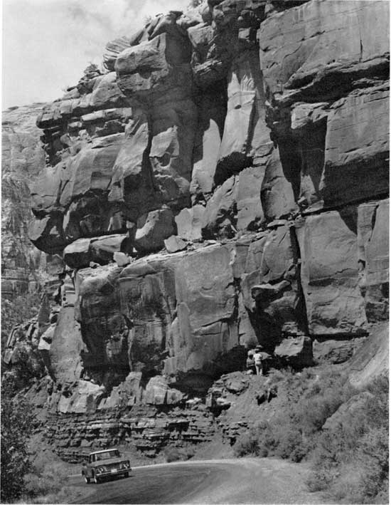
Most beds of "homogeneous" sandstone range from 3 to 15 feet in thickness. They are commonly found as single, massive units within a stratigraphic sequence that is otherwise characterized by well-defined stratification. In some areas, such as the Colorado Plateau, where sandstone constitutes the dominant lithology, massive, "homogeneous" beds occur in great vertical sequences separated only by thin beds of shale (Fig. 1). Within a given bed, there is commonly little visible variation in texture, color, composition, or cementation, so that the thick "homogeneous" units appear to be completely structureless,
Figure 1--Massive "homogeneous" sandstones in the Springdale Formation (Triassic), Zion National Park, Utah. The "homogeneous" beds in this outcrop are typical of many Mesozoic sandstone exposures in the Colorado Plateau. Within such sequences the obvious bedding planes are as much as 30 feet apart. Note the contrast between "homogeneous" beds in the central part of the section, well-stratified deposits near the base, and cross-bedding near the top.
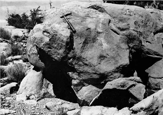
Many of these sandstones seem to be isotropic and break with a conchoidal-like fracture or weather into spheroidal boulders (Fig. 2, 3). In some outcrops, however, thick beds of seemingly homogeneous sandstone can be traced later~illy into units in which many details of stratification and other internal structures are well expressed.
Figure 2--Pottsville Sandstone (Pennsylvanian) exposed near mile 51.66 on West Virginia Turnpike. "Homogeneous" sandstone breaks with a conchoidal-like fracture.
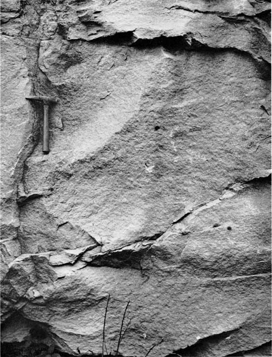
Figure 3--Spheroidal boulder formed by weathering of "homogeneous" sandstone in the Supai Formation (Pennsylvanian-Permian), Grand Canyon National Monument, Arizona.
The samples collected for this study were blocks approximately 6 inches thick and 10 inches long. Generally, one sample was obtained from each outcrop, but for exceptionally thick units, and where detailed vertical variations were to be studied, several samples were obtained from one locality. In formations where seemingly homogeneous sandstones were abundant and crop out over large areas, a number of samples were collected from the same unit at different localities in order to study lateral varlations. All samples were oriented so that the original horizontal surface and top of the sample could be identified easily in the laboratory.
The samples were prepared for radiography by cutting a slice (approximately four inches wide, six inches long, and one-fourth inch thick) perpendicular to the stratification with a large, water-lubricated masonry saw.
The general procedures for making an x-ray picture of a rock slice are outlined in an earlier publication (Hamblin, 1962). Both medical and industrial x-ray units with tungsten targets were used as a source of radiation. Ilford ready-pack non-screen medical x-ray film was used for most radiographs, but equally good results were obtained with Kodak industrial x-ray film type AA and type M. Specimens, ranging from 3 to 5 mm in thickness, were exposed for 2 seconds at 30 milliampers (60 MAS) and 35 kilovolts at a distance of three feet. Satisfactory radiographs of thicker specimens were made by increasing the voltage at a scale of approximately three kilovolts per additional mm of thickness.
Contact positive prints made from each x-ray negative were then analyzed. The major advantage in using positive prints instead of the original negative is that the structural units are shown as black or gray on a lighter background and are easier to analyze. [Note: Throughout this paper, reference to layers ot other structural features as being "light" or "dark" describes the tone on a positive x-ray print. Black or dark layers represent high absorption of radiation, gray or light areas, little or no absorption.] A serious disadvantage of positive prints of some radiographs, however, is that details in both light and dark areas on the negative are difficult to reproduce simultaneously. This problem usually can be eliminated by using a LogEtronographic printer, which is an automatic photographic dodging device. Thus, it is possible to decrease the gross contrast of the negative and increase the detailed contrast simultaneously. [Note: For a concise treatment of LogEtronographic printing processes, see St. John, E. G., and Craig, D. R., 1957, p. 124-133.] Details in both the light and dark parts of the negative are faithfully reproduced, and some features on the negative, invisible to the naked eye, are shown on the LogEtronic print.
Of the 316 samples of "structureless" sandstones analyzed, only 11 were completely homogeneous to x rays. Radiographs of all other specimens revealed some detail either of primary or secondary structural features. In approximately 67 percent of the specimens, considerable detail of the internal structure was clear and distinct. Small, delicate cross-laminae, horizontal layers, networks of burrows, and various other structural features were exceptionally well expressed (Fig. 4). In some samples, layers not much thicker than one grain could be discriminated. Moderate structural detail was shown on radiographs of approximately 20 percent of the samples, but in some areas of the sample characteristics of the internal structure remained obscured (Fig. 5). The type of structure could be determined easily, however, and many features of its size, shape, and orientation were evident. In approximately 10 percent of the specimens, only a skeletal outline of the structural framework was recorded on the radiographs and large areas appeared to be homogeneous (Fig. 6). Three percent of the specimens appeared to be completely structureless. Failure of the radiographs to register structural detail does not necessarily prove that the specimens lack internal structure, for it is possible that sedimentary structures exist within the rock but could not be detected with the type of radiation used.
Figure 4--Radiograph of a sample from a "homogeneous" unit in the Tonganoxie Sandstone (Pennsylvanian), Douglas County, Kansas, illustrating the degree of structural detail obtained from approximately 64 percent of the samples studied. Note the thin cross-laminae and the configuration of the darkest layers, which mark the boundary between sets of strata.
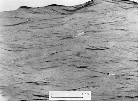
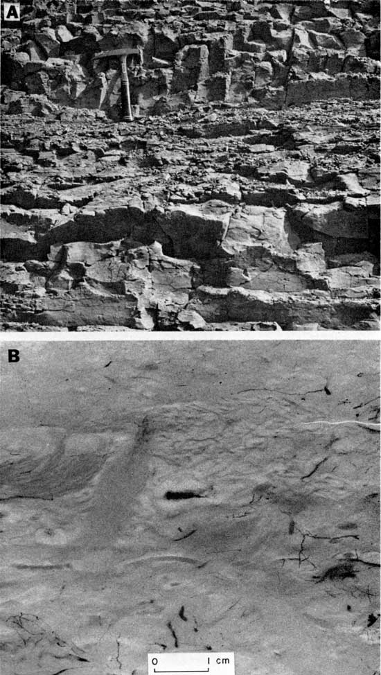
Figure 5--Radiograph of a sample from a "homogeneous" unit in the Coconino Sandstone (Permian), Grand Canyon, Arizona, illustrating the degree of structural detail obtained from approximately 20 percent of the samples.
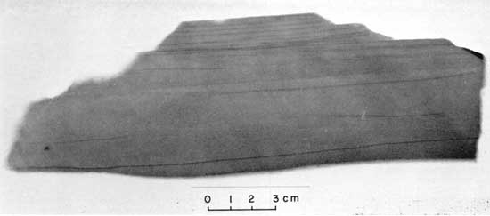
Figure 6--Radiograph of a sample from a "homogeneous" sandstone from the Ferron Sandstone Member of the Mancos Shale (Cretaceous), Emery County, Utah, illustrating the degree of structural detail obtained from approximately 10 percent of the specimens.
Most seeningly homogeneous sandstones contain the same type of sedimentary structures commonly found in deposits in which structural detail is well expressed. Cross-strata and horizontal laminae constitute the basic structural framework and may occur alone or in various combinations throughout a given bed.
Modification of these structures by penecontemporaneous deformation, burrowing organisms, and mineral growth, produces secondary features such as irregular layers, burrows, and various diagenetic structures. Inasmuch as the size of the samples usable for radiographic studies is somewhat limited, it is impractical to study the large structures in their entirety. The percent of samples showing the various structures is given in Table 1.
Table 1--Relative abundance of various types of internal structures found in "homogeneous" sandstones.
| Type of Structure | Percent of Samples | |
|---|---|---|
| Cross-lamination | 46.4 | |
| Micro- | 30.4 | |
| Large-scale- | 16.0 | |
| Horizontal lamination | 26.6 | |
| Irregular layers | 8.7 | |
| Burrows | 8.0 | |
| Diagenetic Structures | 15.0 | |
| Miscellaneous structures | 2.8 | |
| Structureless | 3.4 | |
As a matter of convenience, the internal structures in "homogeneous" sandstones, as revealed by radiography in this study, were grouped as follows:
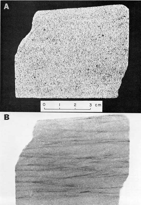
Cross-strata small enough for the entire set to be shown in a 4 x 5-inch specimen. The most common type of internal structure in seemingly homogeneous sandstones is an extremely small-scale variety of cross-stratification (Fig. 7). This structure is generally restricted to fine sand and silt deposits and normaly occurs in sets that range from 0.1 to 0.8 inch in thickness. In cross section it is identical to large-scale planar and trough cross-strata and probably develops mainly by deposition on the lee slope of various types of ripple marks.
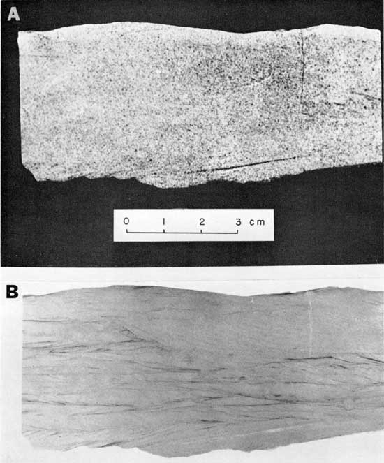
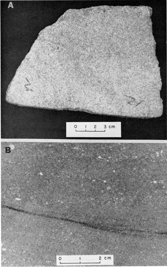
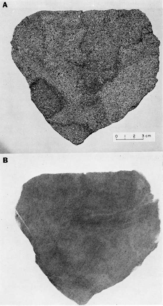
Figure 7--Sample from the Tonganoxie Sandstone (Pennsylvanian), Douglas County, Kansas. A, Photograph showing the appearance of a sawed surface of the sample in reflected light. B, Positive radiograph print showing details of internal structure. Exposure factors: 35 KV, 30 MA, 2 seconds, Ilford non-screen medical film; specimen, 3 mm thick, target-film distance, 3 feet. Basic structure consists of micro-cross-laminae, which occur in sets ranging from 1/2 to 1 cm in thickness. Concentrations of accessory minerals at the boundaries between sets produce greatest contrast. Details of individual layers within the sets are less clear, but are expressed in several places by a series of dots produced by dark material. This sample is typical of a seemingly structureless bed that is approximately 15 feet thick. The size, shape, and orientation of the layers of grains are essentially, the same as in other samples and demonstrate that the "structureless" bed is composed of an intricate network of micro-cross-laminae.
In many beds, micro-cross-stratification constitutes the only type of internal structure. Generally it is remarkably uniform in size, shape, and orientation, but in a few deposits it is extremely variable. In the Dakota Formation sample from Canon City, Colorado, for example, considerable variation can be seen (Fig. 8). The thickness of the sets may range from less than 3 mm to almost 2 cm, and there is apparently a wide range in shape and orientation.
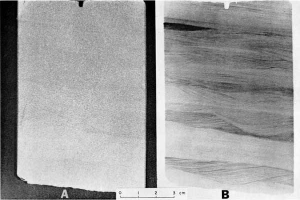
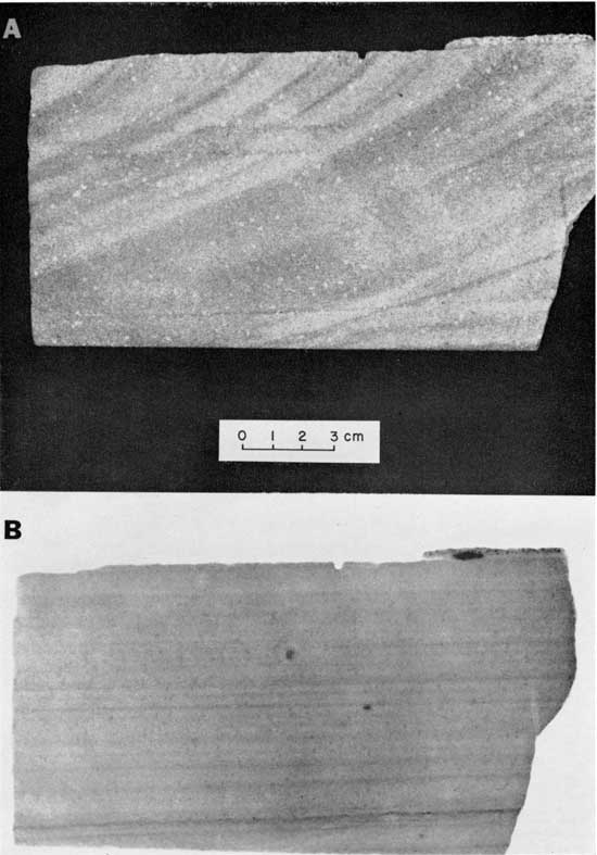
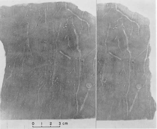
Figure 8--Sample from the Dakota Formation (Cretaceous), Canon City, Colorado. A, Photograph showing the appearance of the specimen in reflected light. B, Positive print of radiograph showing details of internal structure. Exposure factors: same as for Figure 7. The structural framework consists of micro-cross-laminae, which occur in sets ranging from less than 3 mm to almost 2 cm in thickness. The largest set occurs near the top of the specimen and truncates many of the older and smaller sets. Cross-laminae have been disrupted by small tubes approximately 2 mm in diameter, most of which arc oriented perpendicular to the surface of the rock slice. The boundaries of some tubes are sharp, but most are obscure and indistinct; some appear to contain accretionary fillings. These structures probably resulted from the activity of organisims. Fractures clearly defined on the rock surface are shown as white lines on the radiograph.
In many beds of seemingly homogeneous sandstone, sets of micro-cross-laminae do not occur throughout the entire thickness of the rock, but are found in cosets ranging from a few inches to several feet in thickness, interbedded with cosets of horizontal laminae of comparable size (Fig. 9). The cosets are generally separated from underlying units by an erosional surface characterized by small channels, which seldom exceed I cm in depth. Interstratified cosets of micro- and large-scale cross-laminae within the same massive unit are rare, although it is not uncommon to find small and large-scale cross-strata in different massive beds in the same sequence.
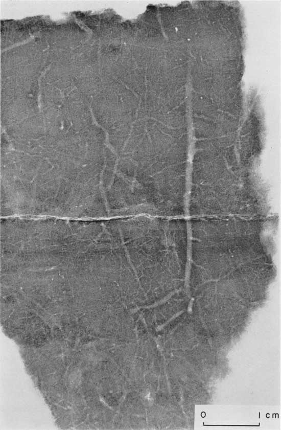
Figure 9--Section of a core of the Berea Sandstone (Mississippian), central Illinois. A, Photograph of polished surface. B, Positive print of radiograph showing details of onternal structure. Exposure factors: same as for Figure 7. The surface of this core seems completely structureless, but vague banding or stratification can be detected on the polished section. Many structural details are clearly shown in the radiograph. Sets of micro-cross-laminae are interbedded with sets of horizontal laminae near the base and top of the sample. Apparent dip of the unit is approximately 10 degrees to the right. Details of horizontal laminae are indicated only by faint lineation. Evidence of scour and fill, typical of rocks containing both horizontal and micro-cross-laminae, is common throughout the sample.
The abundance of micro-cross-laminae in seemingly homogeneous sandstones is one of the most interesting findings of this study. Although this structure is well-expressed in some formations and has been reported in a number of investigations, it has never been considered exceedingly common or widespread. Approximately 30 percent of the samples examined in this study contained micro-cross-laminae, which clearly indicates that this structure is a fundamental type of stratification. In all probability many deposits considered to be medium- or thin-bedded likewise contain this structure and developed by lateral accretion, as sand grains are deposited on the lee slope of small sand waves or ripple marks. Thin-bedded to massive sandstones or siltstones, therefore, do not necessarily indicate that the grains settled out from suspension or accumulated on a planar surface after migrating by saltation. A large percentage of these rocks undoubtedly contain a network of micro-cross-laminae which developed from ripple migration.
As a rule, differences in color, texture, composition, or cementation, which generally express the internal structure of a rock, rarely occur on a scale sufficiently small to accentuate minute and delicate structures. Consequently, micro-cross-stratification in most deposits may be obscure or completely invisible to the naked eye.
Sets of cross-strata too large to be shown in a 4 x 5-inch specimen. Large-scale cross-lamination is not as abundant as the micro-cross-laminae, but its presence in 16 percent of the samples analyzed indicates that it is an important structure in rocks heretofore considered completely homogeneous. This structure is too large to study conveniently by radiographic techniques; therefore, less is known about its size, shape, orientation, and other characteristics. Nevertheless, all of the basic types of cross-stratification of well-stratified deposits probably occur in seemingly homogeneous deposits also.
One of the most striking features of large-scale cross-laminae is the rhythmic pattern developed by simple alternation of layers of dark and light material (Fig. 10, 11, 12, 13.) In most samples the dark layers result from concentration of accessory matter such as clay minerals, mica, and iron oxide. These materials commonly cannot be recognized in the hand specimen, but they stand out on the radiograph because they absorb much more radiation than layers of quartz grains.
Figure 10--Sample from the Ireland Sandstone (Pennsylvanian), Douglas County, Kansas. A, Photograph of sawed surface. B, Positive print of radiograph showing details of internal structure. Exposure factors: same as for Figure 7. Internal structure consists of large-scale cross-laminae, which are shown on the radiograph by concentrations of accessory minerals. Throughout much of the lower part of the sample the dark layers are less than 1 mm apart, whereas in the upper part they are approximately 1 cm apart.

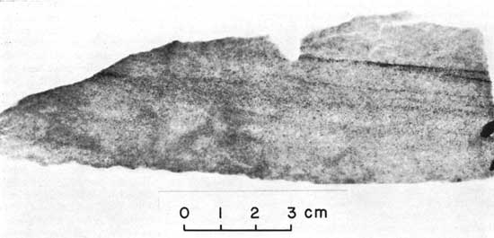
Figure 11--Sample of sandstone from the New River Group (Pennsylvanian), near mile 31 on West Virginia Turnpike. A, Photograph of sawed surface. B, Positive print of radiograph showing details of internal structure. Exposure factors: 10 KV, 30 MA, 2 seconds, Ilford nonscreen medical x-ray film; specimen, 8 mm thick, target-film distance, 3 feet. Internal structure of this sample consists of large-scale cross-laminae shown on the radiograph by alternating dark and light layers inclined at an angle of 9°. Boundaries between layers are relatively indistinct, although the structural units are well defined. Many layers are not parallel, but merge in a downdip direction. A large wedge in the upper part of the sample appears nearly homogeneous to x-rays, although close inspection reveals some laminae with a low apparent dip to the right. Parts of two sets of cross-strata are thus represented, each showing different characteristics. Variations reflecting concentration of accessory minerals can be seen in some layers.
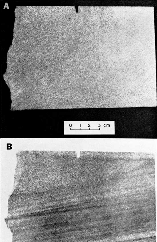
Figure 12--Sample from the Pocahontas Group (Pennsylvanian), near mile 14 on West Virginia Turnpike. A, Photograph of a fresh surface. B, Positive print of a radiograph showing details of internal structure. Exposure factors: same as for Figure 11. Many details of the internal structure are clearly expressed on the radiograph by variations in composition and texture. Thin laminae in the central part of the sample apparently represent concentrations of accessory minerals. Most laminae are not parallel, but bifurcate and subsequently merge, even within the small sample. Variations in texture also are excellent throughout the central part of the sample and delineate layers approximately 2 mm thick. Cross-laminae, inclined to the left, are shown by distinct textural variations near the base of the sample. Layers of coarse material, approximately 1 cm thick, are separated by thinner layers of fine material. Similar textural variations are expressed in the layers near the top of the sample. Three distinct sets of strata are thus apparent within this sample, each of which represents different conditions of sedimentation.
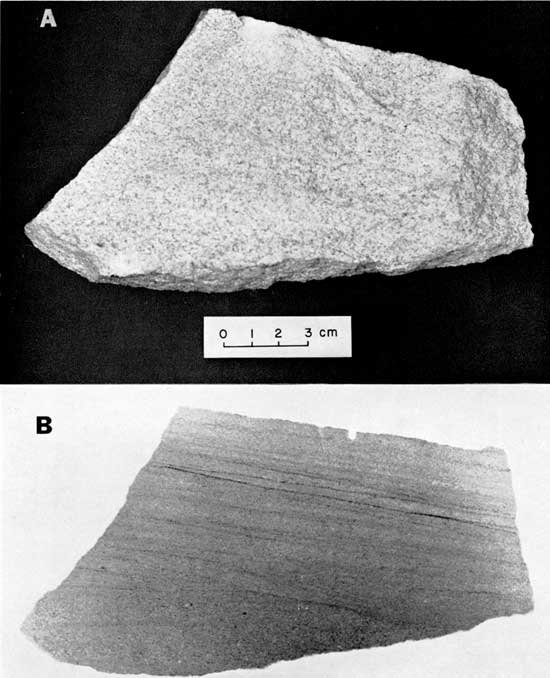
Figure 13--Sample from the Vermejo Formation (Cretaceous), Canon City, Colorado. A, Photograph showing sawed surface of the sample in reflected light. B, Enlargement of a radiograph showing details of internal structure. Exposure factors: 38 KV, 30 MA, 2 seconds, Ilford nonscreen medical film; specimen, approximately 5 mm thick, target-film distance, 3 feet. The internal structure of this rock is expressed by variations in composition, texture, and fabric. Layers of dark grains represent concentrations of light-colored acccssory minerals and delineate the configuration of structural planes within the rock. Variations in grain size and fabric near the base and top, recorded by light and dark tones, emphasize the stratification.
Although the dark material in some specimens may be of secondary origin, and thus produce a type of diagenetic stratification, the ultimate control of alternating dark and light layers can be traced to variations in texture, fabric, or composition.
A1ternating light and dark layers deposited essentially parallel to the original dip of the formation; includes thin undulatory layers as well as those that are perfectly flat. The structural framework of 26 percent of the samples consisted of thin, alternating light and dark laminae. This type of stratification is not restricted to deposits of any particular grain size, as it was found in approximately equal proportions in sandstone, siltstone, and shale, and is present in samples representing essentially every major type of sedimentary environment. It is thus a fundamental structure of "homogeneous" sandstones. Rhythmic horizontal laminae are recognized throughout the entire thickness of many massive beds over 15 feet thick; consequently, the internal structure of such rocks is similar to that of a thinly laminated shale.
The rhythmic pattern, expressed by alternating light and dark layers (Fig. 14), approaches a varve-like constancy in many samples and closely resembles the stratification in the Green River Shale (Bradley, 1929, Plate 11). However, the contacts between the light and dark layers on the radiographs of massive sandstones are generally indistinct and poorly defined because the grains or particles of the dark layers are somewhat dispersed. The laminae are defined by a series of dots rather than by straight lines (Fig. 15), and some laminae appear to be discontinuous.
Figure 14--Sample of the Tonganoxie Sandstone (Pennsylvanian), Douglas County, Kansas. A, Photograph of sawed surface. B, Positive print of radiograph showing details of internal structure. Exposure factors: same as for Figure 7. Horizontal, varve-like layers are typical of many seemingly homogeneous sandstones of the Midcontinent Region. The expression of the laminae on the radiograph results from tonal variations produced by concentrations of mica, clay minerals, and iron oxide cement. As in true varves, the dark laminae are characteristically thinner than the light ones and alternate in a rhythmic pattern. Flat, even laminae are rare in Pennsylvanian sandstones of the Midcontinent Region and are present only in the most fine-grained rocks. The dark layers characteristically merge and bifurcate, reflecting an irregular depositional interface. Some layers are slightly inclined and are truncated by younger units ind thus resemble low-angle cross-stratification.
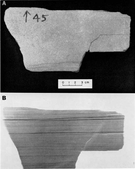
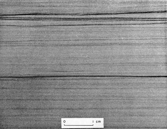
Figure 15--Enlargement of a portion of the radiograph of the Tonganoxie Sandstone shown in Figure 14, illustrating details of the horizontal laminae. Note that many laminae appear to be discontinuous when traced laterally, whereas others thicken and thin. Some thick layers near the top appear to be composed of low-angle cross-laminae and are truncated by overlying layers.
As in true varves, these light layers are almost invariably thicker than the dark layers. In contrast to typical varves, however, flat, even laminae are rare and are found only in the most fine-grained rocks. The dark layers are characteristically undulatory, so that the light layers in many samples thicken and thin laterally. In addition, many dark laminae commonly split into two or more layers. The thicker light layers are thus actually elongate lenses arranged in a somewhat staggered fashion (Fig. 16). Some laminae are truncated by overlying layers where traced laterally, and thus appear as very low-angle cross-strata.
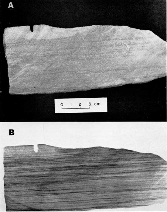
Figure 16--Sample from the Tallant Formation (Pennsylvanian), Osage Hills State Park, Oklahoma. A, Photograph of sawed surface. B, Positive print of radiograph showing details of internal structure. Exposure factors: same as for Figure 7. This sample appeared to be completely structureless in outcrop and hand specimen, but structural detail on the sawed surface shows thin, horizontal bedding ranging from 3 mm to 1 cm in thickness. The radiograph shows thin, horizontal laminae of alternating dark and light layers. Many dark laminae are less than 0.1 min thick and are characteristically undulatory. Thus, the light layers are elongate lenses arranged in a somewhat staggered fashion. The layers probably reflect all uneven depositional interface develped by wave action or currents. In all probability, individual particles were washed in by saltation and were deposited in the parts of the depositional interface.
The origin of rhythmic layering in massive sandstones is not fully understood. Some type of cyclical process was responsible, but it seems unlikely that seasonal changes, which produce most varves, could develop alternating layers in fluvial, eolian, and marine sands. Each layer possibly represents a pulse in the process of sedimentation and could be considered as an influx layer. A rhythmic pattern thus could be developed without relationship to a definite cycle of time in the sedimentary process.
Irregularly shaped lenses, pods, or nodules that pinch and swell parallel to the planes of stratification. The internal structure of mary seemingly honogeneous siltstones and shales consists of small irregular lenses or elongate blebs. This structure is well expressed in some Recent sediments as well as in many ancient deposits, and has been referred to by a variety of names (Sherrill, et al., 1941; Moore and Scruton, 1957; McCrossan, 1958). In deposits where this structure can be seen in outcrops and hand specimens, the irregular layering is generally shown by distinct changes in texture or composition. Common examples described in the literature are lenses of shale in sandstone or irregular limestone nodules in shale. In "homogeneous" rocks, differences in texture or composition are so slight that they cannot be recognized megascopically, and the rock appears structureless. Excellent examples of this structure are found in the Moenkopi Formation (Fig. 17), the Hermit Shale (Fig. 18), and the Mancos Shale of the Colorado Plateau and many shales in the Midcontinent Region (Fig. 19).
Figure 17--"Structureless" mudstone from the Moenkopi Formation (Triassic), Vermillion Cliffs, Utah. A, Photograph of a typical outcrop. B, Positive print of a radiograph made from a thin slice of a sample showing details of internal structure. Exposure factors: same as for Figure 7. Outcrops of "structureless" mudstones of the Moenkopi Formation characteristically weather into irregular blocks, which break down into smaller fragments or chips. Some larger blocks break with a conchoidal-like fracture. Suggestion of internal structure generally can be detected on a sawed surface or in thin section. Structure shown in the radiograph is typical of the irregular layering found in siltstones and shales. Small lenses or pods, ranging from less than 1 mm to more than 3 mm are commonly united by a thread-like connections. Boundaries between most layers are gradatonal and indistinct. Fractures in the rock (shown as light lines) tend to follow the outlines of the lenses and pods. This feature probably explains the crumbly nature of the rock and the tendency for smaller pieces to weather into chips or small disclike bodies.
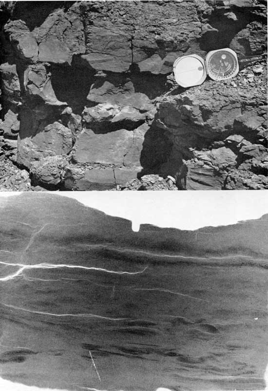
Figure 18--Sample from the Hermit Shale (Permian), Hurricane Cliffs, Short Creek Wash, Arizona. A, Photograph snowing "structureless" units in reflected light. B, Positive print of a radiograph showing details of internal structure. Exposure factors: same as for Figure 7. Much of the Hermit Formation consists of interbedded massive units and layered, blocky shale. The beds that weather into massive units appear structureless, but locally they break into thin layers. The internal structure of these deposits consists of irregular layers or discrete lenses. The lower boundary of a lens is generally sharp and well defined, whereas the upper boundary is typically gradational. Some layers are composed of groups of laminae which essentially conform to the configuration of the lens. As in the Moenkopi Formation, small fractures in the Hermit Shale typically follow outlines of the irregular layers or lenses.

Figure 19--Sample from the English River Formation (Mississippian), Kinderhook, Illinois. A, Photograph of outcrop. B, Radiograph showing internal structure. Exposure factors: same as for Figure 7. The internal structure of this rock is a complex consisting of irregular layering modified by burrowing organisms, root tubes, and penecontemporaneous deformation. Many irregular layers and lenses are surrounded by halos, the origin of which is not known.
The layering in most of these rocks is characteristically very irregular and is composed of lenses or pods less than 1 cm long and 1 mm thick. The lenses are aligned along horizontal planes and pinch and swell along the strike. Some lenses are united by threadlike connections, whereas others are isolated. The boundaries between lenses are generally gradational and indistinct, although some are sharp and well defined. Subtle density differences on radiographs apparently are produced by slight differences in composition or texture, or by differential compaction. Irregular layering is one of the most common types of internal structures in "homogeneous" argillaceous material and was present in every shale sample analyzed.
Various theories have been proposed to explain irregular layering. Van Straaten (1951) attributed irregular layering in Wadden Sea sediments to deposition on a rough surface of marsh vegetation. Moore and Scruton (1957) concluded that irregular layers result from reworking of sediment by burrowing organisms and can be produced from regular layered or homogeneous sediments. The evidence from radiographic studies tends to support the theory that irregular layering, pods, or lenses are forms of sedimentary boudinage developed by lateral tension, which is caused by vertical compaction (McCrossan, 1958).
Tubelike channels, most of which contain accretionary fillings presumably formed by various burrowing organisms. Although previous workers have considered the activities of burrowing organisms to be a major factor in the development of homogeneous sediments, only 8 percent of the samples studied could possibly have been affected by burrowing activity (Table 1). Borings of organisms generally are clearly evident on a radiograph, so there is little doubt concerning the amount of sediment reworked by their activity in the samples studied. Most specimens contained only a few tubes or borings (Fig. 20); complete reworking of material was recognized in only one sample (Fig. 21).
Figure 20--Sample of the Vamoosa Formation (Pennsynvanian), Okfuskee County, Oklahoma. A, Photograph showing the sawed surface of the sample in reflected light. B, Positive print of radiograph showing details of internal structure. Exposure factors: 35 KV, 30 MA, 3 seconds, Kodak industrial film, type AA; specimen, 5 mm thick, target-film distance, 3 feet. An extensive network of borings has disrupted much of the original structure, which was probably micro-cross-laminae. Most borings arc perpepdicular to planes of stratification, although some are horizontal and a few cut the bedding diagonally. The tubes are slightly less than 1 cm in diameter. Where a single boring cuts the bedding, the boundary generally is defined by truncation of the laminae. Where several borings are present, boundaries between borings cannot be distinguished. Accretionary fillings are common in many of the vertical tubes but are not detected in those that are horizontal.
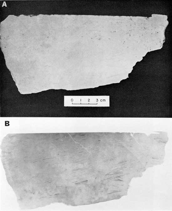
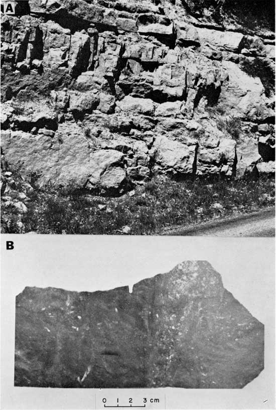
Figure 21--Sample of sandstone from the Kaibab Formation (Permian), north rim of the Grand Canyon, Arizona. A, Photograph of an outcrop of massive sandstone in the Kaibab Formation. B, Positive print of a radiograph showIng details of internal structure. Exposure factors: same as for Figure 7. This is the only sample completely reworked by activity of organisms. No indicaton of original layering is visible from the radiograph. Textural variations outline a number of borings which can be seen throughout most of the specimen. The sizes and shapes of borings are significantly different from those previouly illustrated. Some are more than 3 cm in diameter and taper to a point. Many are filled with reworked material deposited in a manner that resembles tailings of placer deposits. Others are much smaller and appear structurcless. The structure illustrated here commonly is exhibited on weathered surfaces of sandstones in "facies 3" of the Kaibab Formation (E. D. McKee, personal communication).
Disruption of primary structures by organisms occurs generally in the form of small channels or tubes. These structures range from 2 to 5 mm in diameter and may extend across the entire rock sample. As a rule, they are oriented either parallel or perpendicular to bedding planes. Many borings show evidence of some accretionary filling.
Modifications of laminae by various types of mineral growth. In addition to primary sedimentary structures many seemingly homogeneous sandstones contain excellent examples of secondary mineral growth. This type of diagenesis may accentuate, obscure, or even destroy the discontinuities within the specimens that cause the internal structure to be recorded on a radiograph. Generally, the secondary minerals absorb more radiation than the surrounding material and thus are completely black on a positive print of the radiograph. In some samples, however, the diagenetic material absorbs less radiation than the matrix and appears in light tones of gray, or white. In either case, secondary mineral growth generally produces some of the most striking contrasts on the radiograph. The nature of the secondary material, of course, cannot be determined easily from the radiograph. Distribution of secondary minerals in most specimens is independent of primary sedimentary structures, although a few samples contain laminae which seemingly controlled secondary deposition. In some samples (Fig. 22, 23), LogEtronic printing may reveal whether diagenesis destroys the original structures or simply masks their expression.
Figure 22--Sample from the Lyons Formation (Permian), Boulder, Colorado. A, Photograph of sawed surface in reflected light. B, Positive print of radiograph showing details of internal structure. C, LogEtronic print made from the same negative as B. Exposure factors: same as for Figure 8. Markings on the sawed surface suggest some variation in texture and cementation, but details are not clear. Light spots near the top of the sample, suggesting coarse granularity, result from localized reduction of iron; light areas on the right are composed of calcite. The radiograph of this sample (B) reveals large-scale cross-laminae in the lower left. Disruption of some original layering by burrowing organisms is evident, but details are obscure in the dark areas of the print. Structural features on the right half are obliterated owing to greater absorption of radiation in the area of calcite cement. Distribution of the calcite appears more or less random and is not controlled to any noticeable degree by primary structures. With a moderate amount of automatic dodging by LogEtronic printing process, more structural detail is revealed (C). Diagenetic processes and calcite cementation seemingly have destroyed primary structures in the right half of the sample, Inasmuch as original structures are clear where calcite is not concentrated. Some laminae appear to have been disrupted by burrowing organisms but have not been modified otherwise since time of deposition. Laminae and borings on the radiograph are the result of original density contrasts within the rock and are not due to cementing material along selected layers.
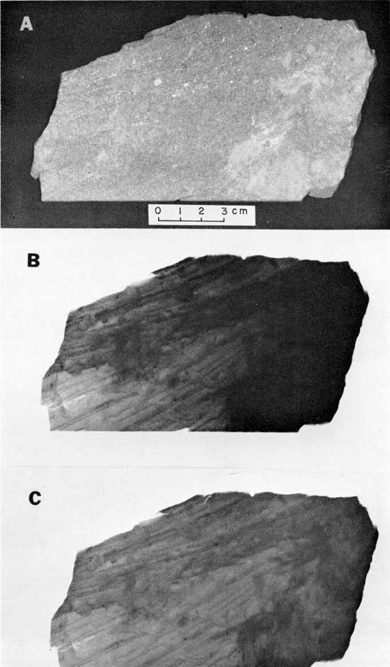
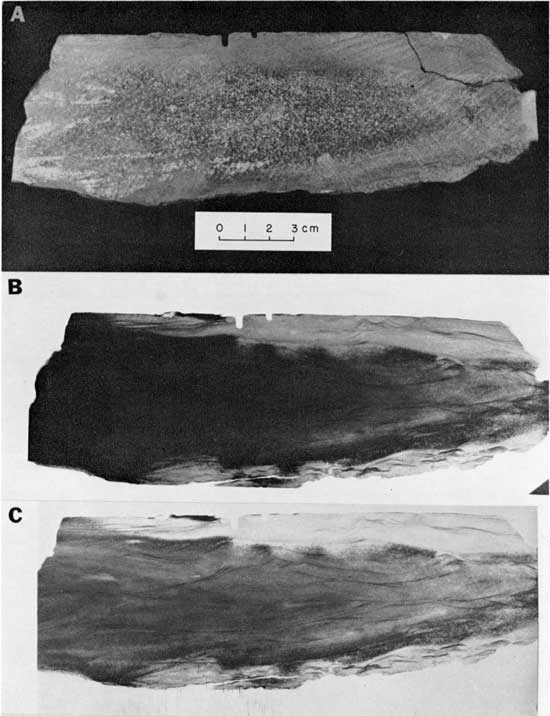
Figure 23--Sample from the Chanute Formation (Pennsylvanian), Washington County, Oklahoma. A, Photograph of sawed surface in reflected light. B, Contact print of radiograph showing details of internal structure. C, LogEtronographic print made from the same negative as B. Exposure factors: 40 KV, 30 MA, 3 seconds, Ilford non-screen medical x-ray film; specimen, 8 mm thick, target-film distance, 3 feet. Differential cementation is suggested by tonal differences on the surface of the specimen (A). The large speckled wedge in the central part contains concentrations of calcite cement. A narrow band 1 to 2 cm wide characterized by a more uniform (lighter) tone almost surrounds the specimen and contains little or no calcite. The rock is a light buff, fine-grained, micceous, quartz sandstone. The contact print of a radiograph (B) shows micro-cross-laminae. Details f the internal structure are obscure in the large wedge in the central part of the specimen where calcite is concentrated. The LogEtronic print of the radiograph (C), in which there has been a moderate amount of dodging, shows micro-cross-laminae that have not been modified to any degree by diagenesis. The only noticible effect of the cement was to increase the density of the sample to x rays.
Joints, small faults, and various structures produced by penecontemporaneous deformation. Microfaults, although not exceedingly common in the samples studied, are well developed and clearly expressed in several specimens. In all probability they represent joints along which there has been slight movement, but some may represent important post-depositional changes. The faults generally occur in conjugate systems, with dips ranging from 75 to 90 degrees; the fracture surface is characteristically clean and sharp. In several samples, however, sets of micro-cross-strata have been disrupted by microfaults and tilted as much as 30 degrees. This displacement may represent significant movement within the rock body that is related either to ma)or tectonic or penecontemporaneous deformation (Fig. 24).
Figure 24--Sample from the Deese Formation (Pennsylvanian), Carter County, Oklahoma. A, Photograph showing a sawed surface in reflected light. B, Positive print of radiograph showing details of internal structure. Exposure factors: same as for Figure 7. The structural framework consists of horizontal laminae, which have been slightly arched, probably reflecting post-depositional movement. Five small faults with displacements as great as 1 cm have disrupted laminae in the right half of the sample. The dark bands along fractures reflect deposition of calcite. The edge of the sample follows a fault plane in which displacement was approximately 1 cm; the calcite mineral zone was 1 cm wide. Disruption of layers near the top of the sample is probably the result of penecontemporaneous deformation or reworking by burrowing organisms. Clusters of black spots near the center top represent localization of diagenetic minerals,
Pseudostratification was visible on the sawed surface of several samples that seemed homogeneous in the outcrop. This false bedding usually was caused by color changes (liesegang banding). The primary structure of such rocks, however, is easily determined by radiography (Fig. 25).
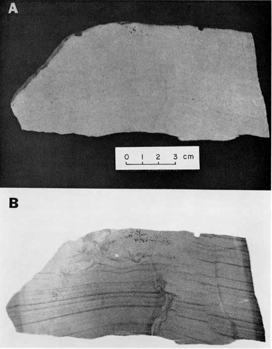
Figure 25--Sample from the Navajo Sandstone (Jurassic), Zion National Park, Utah. A, Photograph of sawed surface in reflected light. B, Radiograph showing details of internal structure. Exposure factors: same as for Figure 23. This sample seemed homogeneous on the outcrop, but the sawed surface revealed color banding. The radiograph indicates that color banding is not related to internal structure, which consists of large-scale cross-laminae. Although traces of the structure appear on the photograph, they are relatively inconspicuous minor lineations compared to the bands expresses by color changes.
Several samples of loess were examined because loess commonly is considered to be a classic example of a structureless, homogeneous sediment. The intricate network of root tubes, clearly visible on the surface of samples long has been recognized as a common characteristic of loess deposits. The nature and extent of these features can better be appreciated by examining them with stereoradiography, which shows the size, shape, distribution, and orientation of the complete root system in three dimensions (Fig. 26).
Figure 26--Stereoradiograph of a sample of loess (Pleistocene) from near Kansas City, Kansas. Exposure factors: 50 KV, 30 MA, Kodak industrial film, type M, 3 seconds; specimen, 3/4 inch thick, stereo shift, 4 inches; focal-film distance, 3 feet. The intricate network of root tubes is the most outstanding feature of the internal structure of this sample. Some tubes form a root system, whereas others appear to be isolated. Expression of the tubes is due primarily to their hollowness, but a narrow dark zone, possibly due to concentration of calcite, generally surrounds the tube and emphasizes the visual contrast between tube and surrounding sediment. The larger tubes are nearly vertical, whereas the smaller tubes to be randomly distributed. Layering of dark material is vague, but can be seen near the central part of the specimen. Coarse material, presumably fine sand grains, is rare but occurs more or less at random throughout certain zones.
In many samples of loess, obscure horizontal layering can be identified on a radiograph. Stratification shown by the dark material cannot be questioned, and grading of the material is suggested by an upward increase in the amount of dark material in several layers (Fig. 27).
Figure 27--Positive print of a radiograph of a sample of loess (Plistocene) from Kansas City, Kansas. Exposure factors: same as for Figure 7. Indistinct dark bands near the base, middle, and top of the loess clearly indicate primary stratification resulting from concentration of dark material along selected horizons. Boundaries of most layers are gradational and indistinct, but the upper boundaries of layers near the middle of the sample are sharp. In these middle layers, dark material grades from a small amount near the lower boundary to a larger amount near the top. Fractures tend to follow the sharp boundaries of the laminae.
Specimens that are homogeneous, as shown by x-ray radiographs. Of the 316 samples analyzed, only 11 were completely homogeneous to x rays (Fig. 28). This does not necessarily prove that these samples do not have an internal structure for it is possible that laminae may exist within the rock with contrasts which are not sufficiently great to be recorded with the type of radiation used. If variations between structural units which are detectable by radiography do not exist, the structure will not be recorded. Moreover, contrasts between structural planes may be greatly reduced if these planes are not perpendicular to the face of the rock slice.
Figure 28--Sample from the Chico Formation (Cretaceous), Simi Hills, California. A, Photograph of a sawed Surface. B, Positive print of radiograph. Exposure factors: 35 KV, 5 MA, 12 seconds, Kodak industrial x-ray film, type AA; specimen, 5 mm thick, target-film distance, 2V2 feet. This specimen is typical of those classified as structureless. Dark material can be seen throughout most of the radiograph, and it appears to be distributed randomly. Vague curved lineations, extending from tile base to near the top, are saw marks. Although some suggestion of stratification can be seen near the upper right margin, this sample is homogeneous to the radiation used.
Completely homogeneous sandstones in which the grains are arranged in a random fashion so that the rock is isotropic may exist but are much less common than has heretofore been realized.
The results of this study indicate that the traditional classification of strata according to thickness has little genetic significance other than indicating the amount of continuous deposition under a given set of conditions. Thick beds may have the same internal structure as thinly laminated deposits, or may contain a complex of micro-cross-laminae, large-scale crosss-trata and rhythmic layers, etc. Beds which appear identical in thickness, texture, composition, etc., could contain distinctly different internal structures, which would reflect a difference in genesis. It is clear from this study that the expression of stratification in outcrop and hand specimen is, to a large degree, fortuitous and may be controlled by many unrelated factors.
Stratification might best be studied by considering an hierarchical ranking of layering within the rock body. The smallest possible subdivision of stratification in medium-grained clastic rocks deposited by water or wind would be a layer of grains which accumulated over the depositional interface at essentially the same time. This layer, here referred to as a "unit stratum," theoretically could be only one grain thick and would result from a single influx of sediment such as a swash on a beach or an avalanche down the lee slope of a dune. The unit stratum is important in that it is the smallest structural unit within the rock and, as such, could be considered as the "building block" of medium-grained clastic deposits. It represents a remnant of the depositional interface and its size, shape, and orientation are controlled by the energy conditions present during the time of deposition. Careful study of unit strata should thus provide important information concerning the environment of deposition because a unit stratum, unlike textural features such as grain size, rounding, and sphericity, is not influenced by previous cycles of erosion, but forms in direct response to the physical conditions present at the time of deposition.
Higher ranks of stratification include groups of unit strata similar in geometry and grain size. These units are similar to the "sedimentation unit" of Otto (1938) and have been referred to as a "set of strata" by McKee and Wier (1953). Several sets of strata united by some common characteristic are called "cosets" (McKee and Wier 1953) and higher orders of stratification may exist up through formations, groups, etc.
Most seemingly homogeneous sandstones are not isotropic, but contain a definite internal structure. Variations in composition, texture, fabric, color, and cementation between structural units are so slight, however, that they cannot be recognized megascopically.
The basic structural framework of "homogeneous" sandstones consists of various combinations of cross-strata and horizontal lamination, which may be modified by penecontemporaneous deformation, burrowing organisms, or secondary mineral growth. Micro-cross-lamination is the most common structural type and indicates that many "homogeneous" sandstones accumulated by deposition on the lee slope of ripple marks. Rhythmic layering occurs in many seemingly structureless beds but probably develops without relationship to a definite cycle of time. Very few "structureless" sandstones result from complete reworking of the sediment by organisms.
Most "homogeneous" sandstones, therefore, do not represent a special sedimentary environment nor do they result from special rates of sedimentation. They develop by vertical and lateral accretion in the same manner as sediments in which stratification and other internal structures are well expressed. Sedimentary structures may be obscure from the time the sediment was deposited or they may be accentuated or obliterated by weathering and diagenesis.
Allen, J. R. L., 1960, The Mam Tor Sandstones: A "turbidite" facies of the Namurian Deltas of Derbyshre, England: Jour. Sed. Petrology, v. 30, p. 193-208.
Bradley, W. H., 1929, The varves and climate of the Green River Epoch: U.S. Geol. Survey, Prof. Paper 158-E, p. 87-110.
Geikie, Archibald, 1903, Text-Book of Geology, ed. 4, v. 1: MacMillan and Co., Ltd., London, 702 p.
Gilluly, James, Waters, A. C., and Woodford, A. O., 1959, Principles of Geology, ed. 2: W. H. Freeman & Co., San Francisco, 534 p.
Hamblin, W. K., 1962, X-ray radiography in the study of structures in homogeneous sediments: Jour. Sed. Petrorolgy, v. .32, p. 201-210.
Longwell, C. R., and Flint, R. F., 1962, Introduction To Physical Geology, ed. 2: John Wiley & Sons, New York, 504 p.
McCrossan, R. G., 1958, Sedimentary "boudinage" structures in the Upper Devonian Ireton Formation of Alberta: Jour. Sed. Petrology, v. 28, p. 316-320.
McKee, E. D., 1954, Stratigraphy and history of the Moenkopi Formation of Triassic Age: Geol. Soc. America Mem. 61, 133 p.
McKee, E. D., and Weir, G. W., 1953, Terminology for stratification and cross-stratification in sedimentary rocks: Geol. Soc. America, Bull., v. 64, p. 381-389.
Moore, D. G., and Scruton, P. C., 1957, Minor internal structures of some Recent unconsolidated sediments: Am. Assoc. Petroleum Geologists, Bull., v. 41, p. 2723-2751.
Otto, G. H., 1938, The sedimentation unit and its use in field sampling: Jour. Geology, v. 46, p. 569-582.
Pettijohn, F. J., 1957, Sedimentary Rocks: Harper Bros., New York, 718 p.
St. John, E. G., and Craig, D. R., 1957, LogEtronography: Am. jour. Roentgenology, Radium Therapy and Nuclear Med., v. 78, p. 124-133.
Sherrill, R. E., Dickey, P. A., and Matteson, L. S., 1941, Types of stratigraphic oil pools in Venango Sands of northwestern Pennsylvania; in, Stratigraphic Type Oil Fields, A. I. Lervorsen, ed.: Am. Assoc. Petroleum Geologists, Tulsa, p. 507-538.
Solowiew, M. M., 1924, The influence of Tubifex Tubifex in the formation of organic mud: Internatl. Review Hydrobiology, v. 12, p. 90.
Twennofel, W. H., 1950, Principles of Sedimentation, ed. 2: McGraw-Hill Book Co., Inc., New York, 673 p.
Twennofel, W. H., and Tyler, S. A., 1941, Methods of Study of Sediments: McGraw-Hill Book Co., Inc., New York, 183 p.
Van Straaten, L. M. V., 1951, Texture and genesis of Dutch Wadden Sea sediments: Proc. Third Internat'l. Cong. of Sedimentology, Groningen-Wageningen, Netherlands, p. 225-244.
Weller, J. M., 1960, Stratigraphic Principles and Practice: Harper Bros., New York, 725 p.
Kansas Geological Survey, Internal Structures of "Homogeneous" Sandstones
Placed on web June 28, 2010; originally published in Dec. 1964.
Comments to webadmin@kgs.ku.edu
The URL for this page is http://www.kgs.ku.edu/Publications/Bulletins/175_1/index.html