Kansas Geological Survey, Bulletin 165, pt. 6, originally published in 1963
Originally published in 1963 as Kansas Geological Survey Bulletin 165, pt. 6. This is, in general, the original text as published. The information has not been updated. An Acrobat PDF version (2 MB) is also available.
A new serial section method combining etching by inorganic salt solution and Bioden peel technique has been developed to study the microstructure of calcified fossils and the micro-texture of limestones. Advantages of this method are improved resolution power of the peel as well as increased ease of handling and speed of production. A plastic embedding technique for small objects has been utilized to produce peels from sections of fragile or hard specimens. Using a precision micrometer, it is possible to obtain exact intervals of less than 5 microns between sections.
The serial section method is one of the most useful techniques for studying organisms in the biological sciences. Students of paleontology have tried to observe the internal structure of opaque fossils in three dimensions. However, it is almost impossible to apply the techniques used on living organisms to petrified organisms.
Texture in fossils is sometimes well preserved and a technique for study of the microtexture, therefore, needed to be developed. There are several problems in using the serial section technique in the study of calcified fossils: (1) that of grinding fossils to maintain parallelism in successive sections, (2) that of producing a finely ground and lightly etched surface, and (3) that of making a permanent record (peel) of the surface.
An apparatus for grinding successive parallel sections was used first by crystallographers (Wülfing, 1890) and was introduced into paleontology by Sollas (1903). Recently, Croft (1950) developed a precise instrument for sectioning, which is a combination of the large micrometer of Zdanski (1938) and a tripod with a sliding specimen-holder. Fossils can be ground at intervals as small as 10 microns with this device.
Walton (1928) was the first to apply a viscous celluloid solution to remove the cast of etched sections of coal balls. This "wet-peel" technique has been developed by many paleobotanists (e.g., Graham, 1933). Darrah's solution, a butyl acetate solution of inflammable cinephotographic film base with a small amount of castor oil and xylol, is one of many excellent peel solutions (Darrah, 1936). The method using Darrah's solution is also adaptable to use in paleontology. One of the greatest disadvantages of the ordinary peel method, including that using Darrah's solution, is that several hours are necessary for the peel to harden, and, consequently, it takes a prohibitive amount of time to prepare a large number of peel sections.
Butler (1935), a paleobotanist, invented the celluloid film method to speed processing of peels. In this method, the etched surface of the specimen is firmly pressed on an acetone-covered celluloid sheet, and the sheet is peeled off when dry. This saves time, and the peel produced is easily handled. Sternberg and Belding (1942) applied this method to the study of bryozoans under the name of "dry-peel technique."
To obtain higher resolution power and smaller intervals between adjacent sections, the author has developed several new techniques. In order to obtain higher resolution power, it is most important that the surface which is to be etched be finely polished. The evenly and finely etched surface necessary for detailed study of fossil microstructure cannot be obtained using simple acid etching solutions alone; variable strength and temperature of the acid solutions are difficult to control, and differential effervescence or bubbling may cause bad effects. However, etching by ion exchange with a water solution of ammonium chloride produces low, uniform optimum relief. The hydrogen ion generated by the hydrolysis of this salt of a strong acid and a weak base reacts slowly and constantly on the carbonate. The buffering effect of the ammonium chloride solution helps to keep the pH constant during etching; therefore, it is easy to keep the depth of etching constant.
If the relief on the etched surface is too low, it is difficult to obtain sufficient shadow contrast needed for photography of the peel because of the limited elasticity of the peeling material. On the other hand, the deeper etching especially needed for the dry-peel technique is sometimes greater than the desired interval of serial sections. But the use of a specially selected cellulose acetate plastic with a specific swelling character makes it possible to produce a peel of a lightly etched surface and still retain sufficient shadow contrast.
It is often desirable to take peels of a specimen at less than 10 microns apart. Because this spacing is beyond the preciseness of Croft's method, a new means of determining the amount abraded was necessary (see Fig. 4).
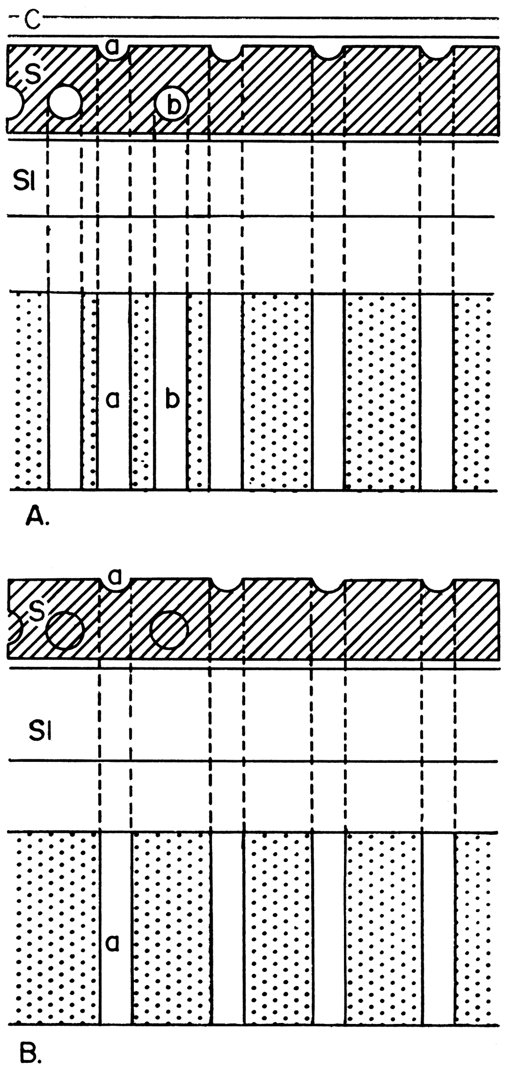
The difference between a photograph of peels and thin sections should be emphasized here (Fig. 1). The black and white contrast as seen in a photograph of fossils or limestone textures is produced by differential transmission of light through the mineral grains. The black and white photographic contrast of a peel is not formed by transmitted light, but rather by a shadow pattern produced by oblique lighting on the irregular surface of the peel. Therefore, the photograph of the peel represents the shadow pattern of a single surface, whereas the photograph of the thin section represents the opacity of the entire depth (thickness) of the thin section (which may be as much as 0.1 mm.). [Note: A microscopic lens system has focal depth. For instance, a × 10 objective lense with a 0.25 numerical aperture and a × 4 ocular has 36 microns of theoretical focal depth. This distance covers the approximate thickness of most paleontological thin sections.]
Figure 1—Diagram illustrating differences in detail observed in a thin section and a peel. A. Thin section of sample shows all features that occur throughout entire thickness of sample. Internal structure at b, as well as at a, will be observed. B. Peel of sample shows only surface upon which the peel was taken. Point a alone will be observed. C, cover glass; S, sample; Sl, slide.
The writer is especially grateful to Masao Minato, of Hokkaido University, and Shoji Ijiri, formerly of Hokkaido University, Alfred G. Fisher, of Princeton University, William A. Berggren, of the Oasis Oil Company of Libya, and Wayne Bamber, of the Geological Survey of Canada, all of whom contributed in several ways to improvement of the technique. Yoshiyuki Hasegawa, of Hokkaido University, cooperated in parts of the investigation. Ivar Hessland, of Stockholm University, kindly permitted the author to use unpublished photomicrographs of serial sections of an ostracode (Plate 2). The paper was written at the suggestion of R. C. Moore and was transmitted for publication to Daniel F. Merriam, of the State Geological Survey of Kansas, who also gave encouragement and assistance.
This investigation was partially financed by a grant-in-aid for fundamental scientific research from the Ministry of Education of Japan.
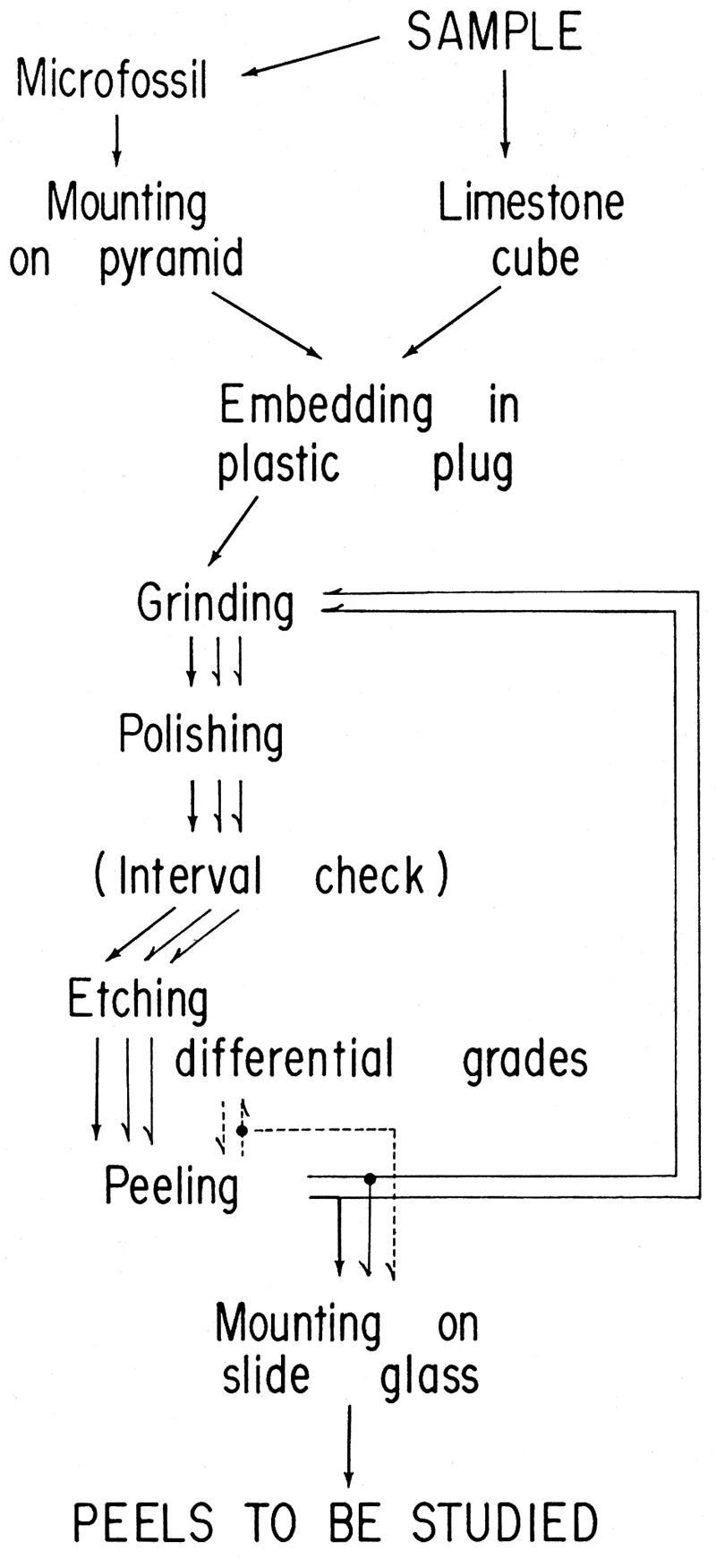
An outline of the procedure for the production of serial micro peels is shown in Figure 2
Figure 2—Flow diagram of new serial rnicropeel technique. Serial peels can be produced by repeating the cycle from peeling to grinding, with an interval check between each peel. To obtain peels of differing contrasts, additional etchings arc performed after each peeling.
There are several reasons for embedding a specimen in a foreign material: (1) Free specimens of microfossils, such as foraminifers or ostracodes, are too small to prepare by hand and embedding is required to give extra volume to the specimen for convenient handling during processing; (2) It facilitates keeping the microfossil oriented and maintaining parallelism between sections; (3) The unexposed area of the fossil is protected from the acid by the embedding material during etching; (4) The embedding material helps in maintaining the proper interval between adjacent sections because it resists abrasion, thus limiting and controlling the speed of grinding; and (5) The smooth surface of the embedding material facilitates removal of the peel.
Embedding materials should have the proper hardness and resistance to water and organic solvents. Application of phenol (bakelite), epoxy, and methacrylate resins as embedding materials are discussed in detail.
Bakelite—Bakelite, which is used for embedding ore samples, can also be used for embedding fossils. Bakelite powder is cast into plugs within a comparatively short time by an ordinary casting device which is a combination of an hydraulic press and an electric heater. The bakelite plug is sufficiently hard and its elasticity is as low as that of calcified fossils, so that grinding can be done more smoothly with a bakelite plug using emery powder than with any other type of embedding material. Resistance of bakelite to an organic substance is almost complete. On the other hand, high temperature and pressure must be applied to the bakelite powder, and thus to the fossil specimen within it. The casting temperature required for bakelite ranges from 120° to 170°C, thus the delicate structure of calcified fossils may be affected by heat. The high pressure necessary to mold the bakelite makes it almost impossible to maintain the initial orientation of a small fossil in such a plug.
Epoxy resins—Epoxy resins are the newest of the major industrial plastics. A wide variety of epoxy resins are available, but their use for the purpose of embedding of fossils is limited. In the United States, more than 40 types of easy-to-obtain resins are marketed by several manufacturers. Among these, Epon 828 (Shell Chemical Corporation) and ERL 2774 (Union Carbide Plastics Corporation) have been used by the author. The monomers of these resins are liquid so that orientation of a specimen inside a plug is easy. These resins cure under atmospheric pressure at room temperature or with the addition of a small amount of heat. The cured polymers are transparent and this property is convenient during the abrasion procedure.
Disadvantages of epoxy resins in comparison with bakelite are their greater elasticity and softness in relation to the calcified fossils. This difference in elasticity between the embedding material and the fossil causes differential abrasion during polishing. The resistance of epoxy resins to ethyl acetate is not as complete as that of a bakelite plug, but after heating a cured epoxy resin plug, peeling can be accomplished without serious trouble.
Methyl or Ethyl methacrylate—Methyl or ethyl methacrylate have been used in the preparation of ultra thin sections of biological materials for examination under the electron microscope. Methyl or ethyl methacrylate monomers are very fluid, optically transparent liquids which have low viscosity at room temperature. Therefore, bubbles are less apt to form in them than in a viscous epoxy resin. Also, impregnation of void space is more complete with this material.
Even though the methyl or ethyl methacryclate polymers are hard relative to other methacrylate plastics, they are considerably softer than the epoxy polymers used by the author. The types of specimens to be embedded in this plastic are limited, therefore, and this method can best be applied to small, delicate specimens such as Recent foraminifer shells. Their resistance to organic solvents is low, even after careful annealing.
Since microfossils occur in all kinds of rocks, ranging from unconsolidated sand to hard, compact limestone, many types of preservation are encountered. The selection of proper plastics to be used with each type of preservation is especially important. The writer would like to discuss the following groups: (1) the bakelite method of mounting microfossils indurated in hard limestone; (2) the epoxy resin method of mounting of well-fossilized, small, free specimens of fusulinids, ostracodes, etc.; and (3) the methyl or ethyl methacrylate method of mounting of delicate specimens with void spaces, such as Recent foraminifers. In general, specimens to be embedded in resins must be dry and free from grease and oil.
Bakelite method—To prepare microfossils or parts of larger fossils in hard limestone, a diamond saw is used to cut a small cube of the limestone with edges of approximately 7 mm. The part of the fossil to be studied should be exposed on one side of the cube. This surface is finished with No. 600 emery powder on an abrasive lap.
The cube, with the prepared surface down, is put in the center of the bottom of a casting cylinder, and a plug approximately 25 mm high is produced following the ordinary casting procedure. As stated before, it is necessary to exercise care in the casting temperature because water vapor produced by excess heating will crack the plug.
Epoxy resin method—In this method, a pyramid mount approximately 5 mm wide at each edge of the base and several millimeters in height is made. Pyramids are molded in small plaster casts: a small amount of moist plaster is flattened, pyramid-shaped holes are impressed into it with a small pointed piece of wood, and it is then allowed to dry. Initiator-inhibited liquid plastic is poured into the holes and left until it hardens. Epon 828 is recommended because it is quick-curing. If just a few pyramids are needed, they can be cut from a small piece of Plexiglas with a saw and file.
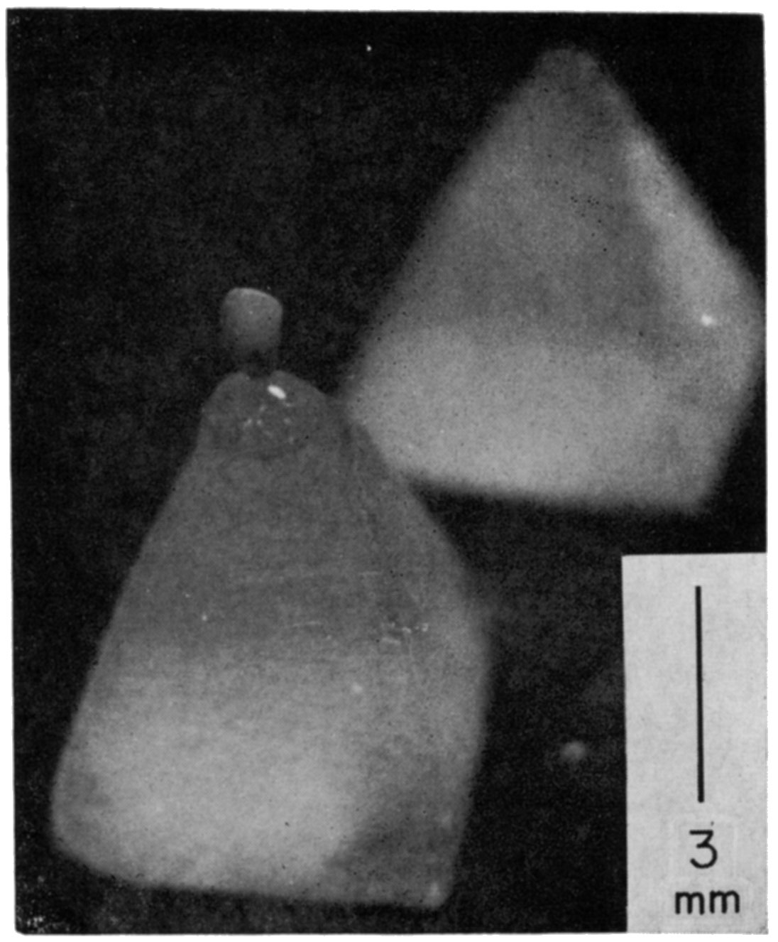
Using a binocular microscope, the fossil is placed on the tip of a pyramid and oriented with a minimum amount of glue (Fig. 3). Dental (phosphatic) cement is recommended. If a glue such as Duco Cement (which is soluble in organic solvents) is used, care must be taken not to contaminate the surface of the fossil with it, because the cement is dissolved by ethyl acetate and spoils the peel.
Figure 3—An epoxy pyramid mount for a small specimen. The pyramid is approximately 5 × 6 mm at the base and 8 mm in height. An ostracode, with desired orientation, is mounted on the tip of the pyramid by use of a very small amount of Duco cement. The specimen (Steusloffina, sp., Pl. 2) is about 1.3 mm in length.
To orient comparatively large specimens such as fusulinids, larger pyramids must be prepared. To emplace these specimen firmly, it may help to groove the tips of the pyramids.
Epon 828 and ERL 2774 are light-colored epoxy resins of medium viscosity. At room temperature they may be hardened rapidly with an initiator or ultraviolet rays into a pale straw-colored final product.
The shape of the embedding plug is cylindrical; the height is approximately 30 mm. For routine work plugs with a diameter of approximately 30 mm were made. Where smaller intervals and more exact parallelism are required for sections, the diameter of the plug may be made larger to facilitate control of the amount ground by offering more resistance to, and thereby slowing down, abrasion of the plug.
To make the plug, a glass tube approximately 30 mm in diameter and cut to approximately 50 mm in length is needed. The end of the cylinder which is to be the bottom should be well polished on a lap and then be stuck tightly to a sheet of clear, flat glass by stearic acid or white vaseline. The whole inside surface of a mold should be covered with silicon dispersion reagent or a thin film of stearic acid or white vaseline. (This will serve to release the mold easily after the resin is cured.) The specimen is placed in the center of the prepared glass cylinder. It may be helpful to put a piece of cross section paper under the glass plate and check the position of the specimen through the transparent bottom. (Each section should be prepared at right angles to the side of the tube.) It is recommended also that the pyramid be stuck to the glass plate by a small amount of stearic acid or vaseline.
Epoxy monomer and initiator of optimum amounts should be mixed thoroughly. [ZZL 0822 (Union Carbide Plastics Corporation) has been used for the initiator of ERL 2774.] An uneven mixing will produce poor results. After the initiator has been added, the monomer mixture should be used immediately. It is good practice to make up at one time only as much initiator-monomer mix as can be used in a day's work.
Because both monomer and initiator are viscous and difficult to measure in small amounts, when one or a few plugs are needed, this measurement is best done with a syringe. The mix is carefully poured into the mold directly upon the specimen so as not to displace it from the tip of the pyramid. This method helps to remove small bubbles that adhere to the fossil's surface.
It is almost impossible to avoid entrapping numerous small air bubbles caused by the mixing of the viscous monomer and initiator. Most of these bubbles will float to the surface and vanish. If they remain in the plug and float above the specimen, there is no trouble. If bubbles occur at the level of the specimen, however, it will be ruined during polishing. To avoid bubbles, the mold with the impregnated specimen is placed in a vacuum desiccator and alternately subjected to a vacuum and atmospheric pressure until clear. The vacuum should not be so great as to cause the mix to boil.
The time required to cure the monomer mix at room temperature ranges from 1-3 hours for Epon 828 to less than an hour for ERL 2774. After the mix becomes hardened, the cylinder is separated from the glass bottom and the plug pushed out. Any lubricant on the surface of the plug should be completely removed.
The hardened polymer is easily attacked at room temperature by the ethyl acetate used in the peeling procedure. To complete the polymerization and give resistance to the organic solvent, the plug should be heated to approximately 90°C for at least 3 hours after removal from the mold.
Methyl or Ethyl Methacrylate method—It is particularly important in the case of air-encapsulated specimens, such as Recent foraminifers, to completely impregnate the specimen with embedding material. Impregnation of small void spaces is difficult with epoxy because of its high viscosity. In addition, epoxy polymer is too hard for the grinding of a small, fragile specimen. Therefore, methyl methacrylate or ethyl methacrylate, which are less viscous than epoxy, are used for embedding such a specimen.
Methyl and ethyl methacrylate are not much different in physical character when polymerized. [Note: The methyl methacrylate monomers are inflammable organic compounds with relatively low flash-points. When handling them, adequate ventilation should be provided and open flames and sparks caused by static electricity must be avoided.] However, the latter has a higher boiling point and is thus somewhat less subject to bubbling during curing.
The most practical method for' initiating polymerization of acrylic monomers involves the use of heat in combination with certain soluble organic peroxide (solid) initiators such as benzylperoxide. An optimum amount of initiator ranges from 0.02 to 0.1 percent by weight of the monomer. [Note: The methyl methacrylate monomers as shipped contain hydroquinine as an inhibitor to prevent polymerization during shipment and storage. Although it is generally possible to counteract the effect of the inhibitor by adding an excess of initiator, hydroquinine imparts a yellowish color to the finished plugs, and it is better to remove it prior to polymerization. The inhibitor can be removed with sodium hydroxide and sodium chloride solution. For detailed procedures see Rohm and Haas Company (1960).] After the initiator has been added to the inhibitor-free monomer and dissolved by stirring, the monomer mix should be used immediately, just as in the case of epoxy mix.
Void spaces in the microfossil which open to the outside can usually be impregnated by merely dipping the specimen in the methyl methacrylate mix. If this is not successful, then the simplest method is to weakly centrifuge the specimen with methacrylate mix for a few minutes, or to put it in a vacuum desiccator and subject it alternately to a slight vacuum and atmospheric pressure.
If orientation of the specimen is not required, the following procedure may be followed. A flat-bottomed glass tube with approximately 20 mm inside diameter and 30 mm in height can be used as the mold. A base on which the specimen is supported then can be made by pouring a 5-mm layer of methyl methacrylate monomer mix into the mold and the mold covered by two or three layers of tightly fitted cellophane. This base should be heated at 70°C under normal atmospheric pressure until the mix forms a gel that is stiff enough to support the specimen.
The specimen in the methacrylate mix is transferred into the mold and placed in the center of the base layer. It is then baked in an oven at 70°C until the mix is hardened. The time required for polymerization of the methacrylate mix is dictated by the amount of initiator and remaining inhibitors. In general, curing takes at least 12 to 18 hours.
If orientation of the specimen is necessary, the following procedure may be used. After the void spaces of the specimen are impregnated by the mix, the specimen is transferred to a small gelatin capsule and the cap put firmly in place. It is baked in an oven at 70°C until the mix is hardened, but not completely polymerized. A small cube containing a specimen can be cut from the plug with a sharp knife, and the cube can be oriented on the base layer in the mold. If it is not possible to orient the specimen in the mold, a pyramid of epoxy or Plexiglas can be prepared and the cube cemented on the tip of it with the desired orientation.
To give resistance to ethyl acetate used in the peeling procedure, the polymerized plug should be annealed for more than 10 hours at 90°C under normal atmospheric pressure. After annealing, the plug should be cooled slowly to room temperature.
Before etching, the surface of the plug exposing the fossil section is finished by grinding and polishing. The resolution power of the peel obtained is much influenced by the smoothness of the fossil surface. Grinding and polishing techniques employed are similar to those used for preparing ore minerals. Because calcified fossils are very soft and fragile, special techniques are needed. Preliminary grinding is almost unnecessary with bakelite embedding, but an epoxy or methacrylate plug must be ground to prepare the irregularly cured bottom surface, or, if a pyramid is used, a thickness the height of the pyramid should be ground down. Where the section occurs near the tip of the pyramid, use fine emery abrasives to avoid scratching the specimen. Methyl methacrylate-impregnated fragile foraminifers need special care because these objects are small. The mechanical wheel grinds a methyl methacrylate plug very rapidly, so that grinding may easily loosen the specimen. The top of a plug should be ground parallel to the bottom and finished on a flat glass with fine emery abrasive to facilitate the interval check.
Grinding Procedure—A finely frosted glass plate approximately 6 × 8 inches and 1.1 inch thick should be wet slightly with ethylene glycol before being used. Ethylene glycol and No. 800 to 1200 emery powder are mixed to a cream like mixture, and a small amount is spread on the plate with a slightly wet plastic darkroom sponge. The fossil surface is ground on the glass plate until it is covered by uniform-sized pits which may be observed under a binocular or reflection microscope. A bakelite plug is normally more smoothly finished by the grinding than other kinds of plastic plugs. Epoxy plugs have a tendency to stick to glass under certain wet conditions; therefore, the proper wetness must be determined experimentally. Wetter conditions are recommended for grinding methacrylate plugs.
Polishing Procedure—Any type of motor-driven horizontal lap may be used for polishing. six- or eight-inch wheels are the most convenient to operate, and medium speeds of 1,000 to 1,500 surface feet per minute are most satisfactory.
Polishing of calcified fossils is generally more difficult than polishing of hard ore minerals. For best results in polishing fossils, a fine cloth lap and alumina suspended in distilled water should be used. Selvyt™ (Buehler Company, Evanston, Illinois) and silk polishing cloth are recommended for the polishing of calcite fossils. Selvyt is a cotton cloth of medium nap used for final polishing. A gamma polishing alumina suspension usually gives better results than a normal alumina suspension. Miracloth™ (Buehler Company, Evanston, Illinois) used with fine polishing alumina is suitable for polishing a limestone cube in a bakelite plug.
Best results are obtained by a procedure that keeps the plug constantly in motion relative to the wheel, under light pressure, and with frequent change in the direction of polishing. For best results, hold the plug on the wheel for a few seconds, then remove from the polishing lap; repeat until the proper polish is obtained. A well-polished surface is easily identifiable under a reflection microscope by the transparent aspect of the fossil in a dark-reflecting field, or to the naked eye by its mirror-like luster.
The degree of wetness of the cloth used for final polishing influences the result. To determine the proper wetness, the plug is removed from the wheel and a check made of the time necessary for the polishing film to dry. In general, drying should not take longer than several seconds at room temperature.
Resistance of fossils to polishing is usually greater in epoxy and methacrylate plastics than in bakelite. Excess polishing causes an undesirable relief between plastic and fossil.
Scratches and pits on the fossil surface may be caused by:
Interval Check—The most difficult task in this operation is maintaining parallelism of the sections in order to control the intervals of serial peels. Two methods are discussed: one which uses devices already developed for parallel grinding, and the other, for fossils ground by hand, which uses a precision micrometer for checking.
If complete accuracy is not necessary, Zdansky's micrometer microtome (Zdansky, 1938) or Croft's tripod microtome (Croft, 1950) can be used. The latter is more convenient and gives uniform results. The disadvantages of using these devices for serial sectioning is that the specimen or the specimen holder has to be dismounted from the microtome before polishing and etching, and it is difficult to reattach it in the same position.
Where accuracy of less than 10 microns is required, the following method is suggested: Grind the plug by hand for some minutes maintaining the same speed; measure the difference in thickness by micrometer; then polish to the desired interval. The amount of abrasion is generally small, and it is possible to make it nearly constant each time. Although the thickness of section abraded cannot be exactly constant, a record of the amounts ground allows accurate restoration of the three dimensional picture of the specimen.
To measure the difference in thickness, many devices can be used. Mechanical amplifying gauges (an upright-type dial gauge, for example) are satisfactory for routine work. A pneumatic precision gauge will give a high degree of accuracy.
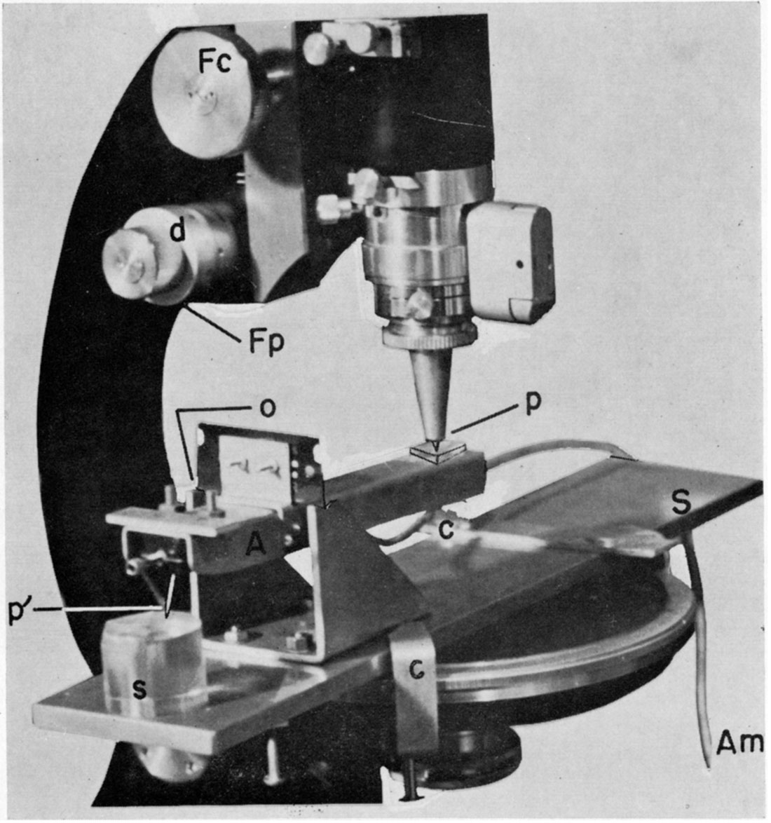
A simple device for measuring the interval between peels is shown in Figure 4. The assembly is installed firmly on the stage of a microscope in an upright position. The microscope should have a precision focusing adjustment on which graduations of two microns (= .002 mm) are marked.
An arm, which is supported, is free to move vertically at a point (razor edge), which is a fulcrum. A steel cone is screwed into the lower end of the microscope tube and the sharply pointed tip touches the arm at point p. At the other end of the arm there is a phonograph pick-up with a crystal cartridge and a needle, p'. The distance between p and o is twice that between p' and o. The polished plug to be measured is placed beneath the needle, and, by using the coarse focusing knob, the needle is brought into proximity with the surface of the plug at the point where it is to be measured. Since the razor blade mounted on this device acts as a fulcrum, raising the steel cone at p will lower the needle at p'. The height of the arm is designed so as to keep it close to horizontal when the tip of the needle almost touches the surface of the plug. When the needle and plug are apart, ordinary vibrations generated in the laboratory which are conducted through the knife edge give almost no electronic excitement to the crystal in the cartridge. By turning the precision focusing knob of the microscope to elevate point p, the crystal cartridge is lowered. When the needle touches the plug, vibrations are collected by the needle which then excite the crystal. The excitement is amplified by an electronic amplifier system and the moment that the needle touches the surface of the plug can be distinguished by use of earphones or a loud speaker. This operation may be repeated a few times in order to be sure of the exact moment of contact; the micrometer scale on the precision focusing knob is then read.
After the final polishing procedure in the next cycle, the plug is again placed in the same position. The needle is lowered by turning the precision focusing knob to the point of contact in the same fashion as described above. The actual difference in thickness of the plug is given as one-half the measure indicated by the precision focusing knob because of the ratio of the distance between o-p and o-p', In actual practice, three positions on the surface of the plug should be checked so that the deviation from parallelism is known.
The bottom of the plug and the stage where the plug is placed should be kept clean to maintain preciseness. It should also be pointed out that a considerable change in temperature of the plug between measurements may cause errors because of thermal expansion of the plug.
One source of mechanical error is a function of the deviation of the arm from a horizontal position; this method should not be applied where the arm movement on the fulcrum is more than 20 to 25 degrees.
The polished surface is rubbed lightly with a soft, clean plastic sponge and soap in running water to remove stains and clinging particles of abrasive. Specimens are then stored in clean glass-covered containers. Plugs should be handled carefully, and the polished surfaces should not be touched by hand.
A 2-percent water solution of ammonium chloride is used for etching. This may be stored in polyethylene bottles. Each sample is placed in a glass or plastic pan with the polished surface of the fossil up. The surface of the plug should be horizontal, to eliminate uneven etching. The pan is then filled with the ammonium chloride solution, with an initial pH of about 5.4, until the specimens are covered by about one inch of solution. The time required for etching depends upon the conditions of preservation and purpose of study. The first section tested usually will indicate the amount of time necessary for etching.
If examination of the peel under comparatively high magnification is desired, etching should be of short duration in order to obtain a higher resolution power and greater detail of the fossil structure. If a photograph taken under low magnification is desired, a longer etching interval is required to obtain greater contrast. Therefore, it is recommended that a series of peels having graded shadow contrast be prepared from each section by successively increasing etching time.
For example, 8 minutes were required to make the proper peels from the epoxy-embedded free specimens of fusulinids from Pennsylvanian rocks of Kansas (Plate 1) for observation under × 200 magnification, 20 minutes for × 50, and 30 minutes for × 20 magnification. Specimens of Yabeina sp. from Permian limestones of Akasaka, central Japan, required etching for 8-20 minutes for higher magnification, 35 minutes for × 50, and 45 minutes for lower magnifications. Although no visible difference in specimens was observed, duration of etching of a specimen from the Akiyoshi Limestone, of western Japan, was 5-10 minutes less than that of specimens of the same species from Akasaka. Very fragile Danian planktonic foraminifers, embedded in a methyl methacrylate plug, required a maximum etching time of from 5-8 minutes. The shell structure was dissolved if etched beyond that time.
Figure 4—Device used to measure interval between peels on an embedded sample which is being ground and polished. Arm, A, is an aluminum sheet with a crystal phonograph cartridge installed in one end of it. A sealed wire connects the cartridge with an amplifier circuit, Am. The fulcrum is a safety-razor blade fitted into brass bearings. The tip of a steel cone, p, touches a flat glass plate on the arm. A flat brass sheet, S, is firmly installed on the microscope stage with clamps, c. Fc, coarse focusing adjustment knob; Fp, fine focusing adjustment knob; d, micrometer scale; p', needle; s, sample to be measured for interval check; o, fulcrum.
The effects of temperature on etching are less with an ammonium solution than with other acid solutions. To obtain a constant amount of relief necessary for a constant amount of shadow contrast for photographic prints of the peels, it is recommended that a specific solution temperature be maintained. Temperature of the solution in the above experiments was 20°C.
After the plugs are etched, they are removed from the solution and placed immediately in slowly running water and rinsed for about one-half minute. The etched surface should be guarded against contact with any medium.
The etched surface should be dried completely before making peels. To save time, rinse the plug in hot water for a few seconds and dry under an ordinary commercial infrared lamp. Using a 250- to 300-W tube, place the plug under it for about 3 minutes from a distance of approximately 20 cm.
Film characteristics necessary to obtain the best peels are strength, high resolution power, and rapid evaporation of the solvent contained in it.
Fukami (1955) developed the film replica system using ethyl cellulose or acetylcellulose films for the positive replica system in electron microscopy. Plastic films are prepared as follows: spread a 7-percent trichloroethylene solution of ethyl cellulose [Ethocel of Dow Chemical Company. 7 c.p.s.] on a clean flat glass and make a film approximately 50 microns thick, allowing the solvent to evaporate at room temperature. Acetylcellulose film is made by 7-percent acetylcellulose acetone solution following the same procedure. Ready-made acetylcellulose film is sold under the trade name Bioden RFA. [Note: A product of Oken Shoji Co., Ltd., Ginza E., 6-7, Tokyo. The 34-micron thick film is blue and transparent; 80-micron thick film is yellow; dimensions of both are 10 by 12 cm.] The most significant characteristic of the Bioden RFA film is that of swelling in a particular solvent. Therefore, where a piece of plastic film is touched by solvent, it softens and swells, and the surface is forced onto the etched surface. The solvent penetrates the plastic film and evaporates from the surface within a short time. A well-made peel is tough and will not tear.
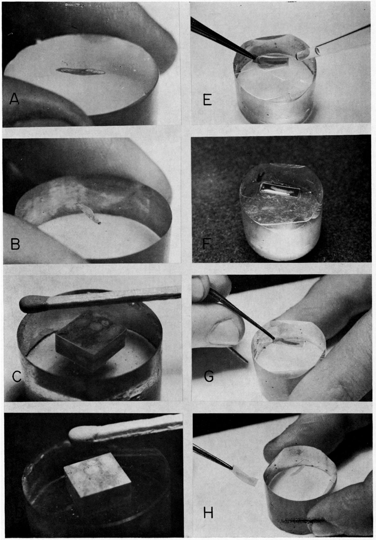
The plastic film is applied as follows: the plug is oriented horizontally and a few drops of ethyl acetate are placed on the etched surface by medicine dropper. A piece of plastic film is immediately placed on the surface by "rolling" on the film from one edge of the surface, pushing out the air bubbles that otherwise might be trapped in the peel. The film must be larger than the object so that part of the adjacent smooth surface of embedding material is covered. The film adheres to the etched surface by surface tension. Excess ethyl acetate is removed by a small piece of filter paper immediately after the applied film adheres to the surface. The film is allowed to harden by drying, a process which takes only a few minutes at room temperature (Fig. 5).
Figure 5—Photograph showing ground, polished, and etched surfaces of epoxy plugs and how plastic film is applied and removed from an etched surface. A. Smooth but semitransparent surface of epoxy plug ground with very fine abrasive (emery 3200). B. Final polished surface, with a fusulinid (Pl. 1) embedded in it. C. Cube of Neoschwagerina-limestone from Akasaka, central Japan, embedded in epoxy plug, with a well polished surface produce by gamma alumina on a silk lap. Surface of plug has mirror-like luster, and slight relief of fossils can be observed in reflected light. D. Same plug after etching. Note luster of limestone surface is gone and cube appears somewhat powdery. E. After application of ethyl acetate on surface by medicine dropper, a piece of plastic film is placed on the surface. Air bubbles are pushed out by "rolling" from one end to the other as the film is applied. F. Excess ethyl acetate is removed by a small piece of filter paper (not shown). G. After a few minutes, when film is dry and hard, a gentle push may be given on a corner with tip of tweezers. H. Peel is removed carefully from etched surface by grasping it with tweezers and pulling gently.
The contained water in ethyl acetate will cause trouble, especially at lower room temperatures and in a wet atmosphere; thus, a good quality acetate should be used. Static electricity is easily generated in the plastic film by slight friction. Therefore, foreign particles are apt to be attracted and the film becomes dirty. To avoid this contamination, film should not be left outside the container for long periods of time.
Peels should be stored in small glass bottles for each section or each different grade of etching. Peels remain in good condition for a long time if they have been well prepared. When needed, the peel can be taken from the bottle and inserted between glass plates for study or photography.
Also, peels can be sealed permanently between two glass plates as follows: the peel is put on a clean, grease-free glass microslide, a very small amount of epoxy mix is added on the corner, and the peel is covered with another glass microslide. Several such pairs of slides are pressed in a vice and epoxy mix pasted carefully on the edges of them; they should be left until the plastic becomes hard. In this procedure, be careful that the plastic used to stick together two microslides does not contact the peel inside or the peel will lose its shadow contrast completely. A small piece of very thin onionskin paper which is labeled can be sealed in the plate for identification.
The small, uniform vertical pressure of up to a kilogram per square centimeter exerted on peels placed between two microslides does not destroy the relief. This method of sealing cannot be applied to peels to be studied under high magnification because a microslide is too thick for a short focal length lens. In such cases, an ordinary coverglass with Duco cement is used.
Curling of a peel usually results from the film being removed too soon from the surface of the plug. Some curling does not affect use of the peel, but if peels curl badly, trim them to as small a size as possible with sharp scissors. Extremely small trimmed peels may be handled by a pipette instead of a pair of tweezers.
The shadow contrast in peels is caused by contrasts in relief on the peeled surface when viewed under oblique light. Usually, a regular microscope can be used satisfactorily for the study of peels under relatively low magnification. For the study of peels under high magnification, especially those made from a very finely etched surface, a phase contrast microscope improves the contrast detail greatly.
Plate 1—Photomicrographs of serial peels of Triticites ohioensis Thompson, from Johnson County, Kansas. The sections are approximately 17 µ apart, except for the bottom two which are 32 µ apart. Note how the series shows the three dimensional aspect of the septal fluting throughout the chambers, development of chomata, proloculus, etc. The first five sections are parallel sections; the bottom one is a perfectly oriented axial section.
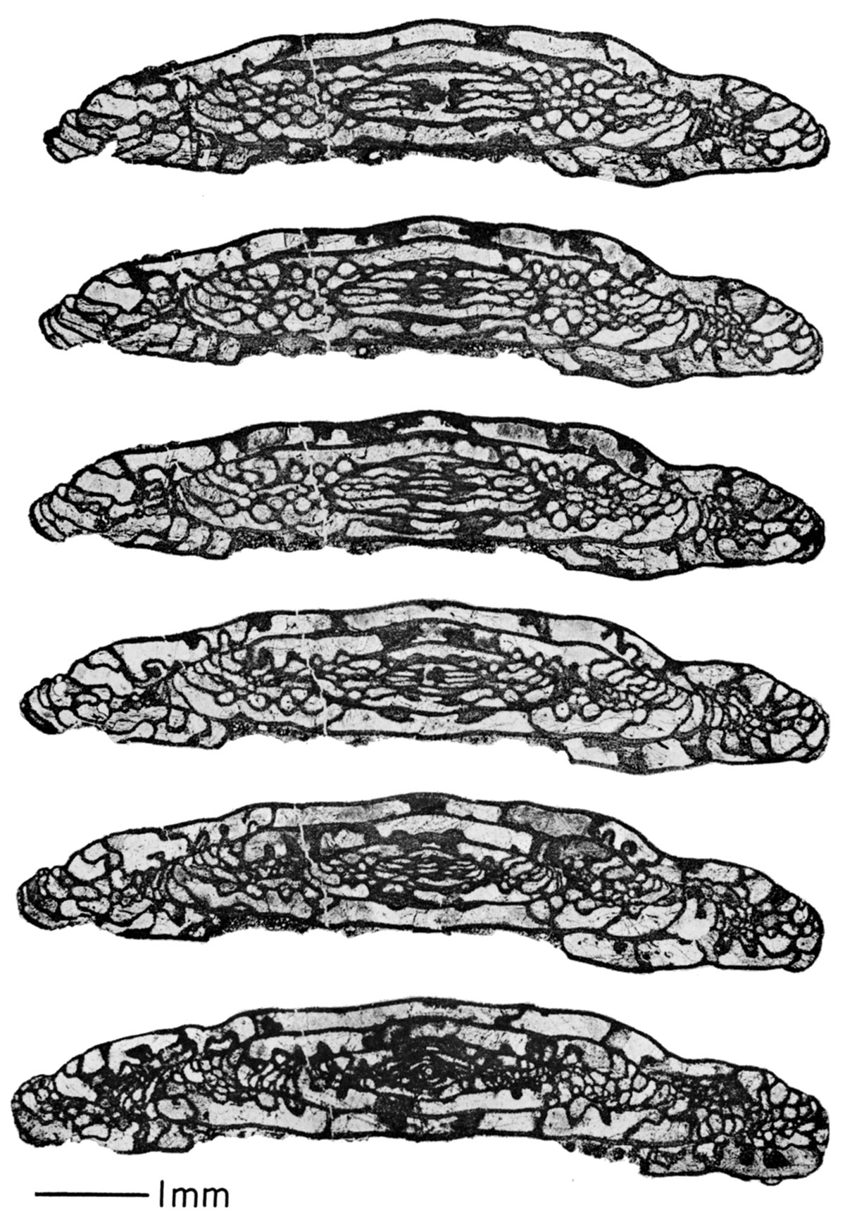
Plate 2—Serial sections of the ostracode, Steusloffina sp., Ashgillian, Upper Ordovician, derived from the submarine early Paleozoic in the Bothnan Gulf, northern Baltic area. The specimen was collected and identified by Professor Ivar Hessland of Stockholm University; serial sections were prepared by the author at the request of professor Hessland. The sections are cut along planes perpendicular to the hinger line of the specimen. Section 1 is through the posterior part of the postero-median region. The serial section ends at the anterior top of the mid-anterior region of the carapace. The height of the specimen in section 24 is 786 microns. The average interval between sections is about 17 microns. (Photomicrographs of the peels appear here at 3/4 the original plate size and screened at 133 lines per inch.)
Arnold, Z. M., 1958, A precision sectioning instrument for microfossils: Micropaleontology, v. 4, no. 1, p. 103-112.
Barringer, A. R., 1953, The preparation of polished sections of ores and mill products using diamond abrasives, and quantitative study of point counting methods: Trans. Inst. Min. Met., v . 63, p. 21-41.
Beckmann, Heinz, 1951, Hilfsmittel zum Schleifen von Microfossilien: Palaönt, Zeitschr., b. 24, no. 1-2, p. 91-94.
Buehler, Co., Ltd., 1959, AB Metal Digest: v. 5, no. 3.
Butler, A. J., 1935, Use of cellulose films in paleontology: Nature, v. 135, p. 510.
Caldwell, F. E. S., 1935, A simple method of taking serial sections: Geol. Mag., v. 72, p. 521-523.
Carruthers, R. C., 1910, On the evolution of Zaphrentis delanouei in Lower Carboniferous times: Quart. Jour. Geol., Soc., v. 66, p. 523-538, Pl. 36-37.
Croft, W. N., 1950, A parallel grinding instrument for the investigation of fossils by serial sections: Jour. Paleont., v. 24, no. 6, p. 693-698.
Easton, W. H., 1942, On improved technique for photographing peel sections of corals: Jour. Paleont., v . 16, no. 2, p. 261-263.
Finck, Henry, 1960, Epoxy resins in electron microscopy: Jour. Biophys. and Biochem. Cytol., v . 7, no. 1, p. 27-30.
Fukami, Akira, 1955, Experiment concerning replica preparation method (II). On a new rapid and reliable positive replica process (filmy replica system): Jour. Electron Microscopy, v. 4, no. 1, p. 274-278. (Japanese with English resumé.)
Glauert, A. M., Rogers, G. E., and Glauert, R. H., 1956, A new embedding medium for electron microscopy: Nature, v. 178, p. 803.
Honjo, Susumu, 1960, Serial replica method for fossils: Kagaku no Jikken, v: 11, no. 9, p. 745-752. (Japanese.)
Honjo, Susumu, 1960, A study of some primitive Neoschswagerina by a new serial section technique: Jour. Fac, Sci. Hokkaido Univ., ser. 4, v. 10, no. 3, p. 457-470.
Ida, Ichiro, and Arai, Yuzo, 1959, Polishing and lapping of 100 MC crystal: Electronics Digest, v. 12, p. 201-210. (Japanese. )
Ives, William, Jr., 1960, Evaluation of acid etching of limestone: Kansas Geol. Survey Bull. 134, p. 289-331.
Kennedy, G. C., 1945, The preparation of polished thin sections: Econ. Geol., v. 40, p. 353-360.
Kesling, R. V., 1957, A peel technique for ostracod carapaces and structures revealed therewith in Hibbardia lacrimosa (Swartz and Oriel): Bull. Nat. History Museum, Univ. Michigan, v. 14, no. 4, p. 27-40.
Königsberger, J., 1908, Neue Apparate und Beobachtungsmethoden: Zentralblatt MineraL, p. 563-573.
Kremp, Gerhard, 1953, Preparation of oriented sections of microfossils: Micropaleontologist, v. 7, no. 1, p. 29-33.
Meyer, C., 1946, Notes on cutting and polishing thin sections: Econ. Geol., v. 41, p. 166-172.
Minato, Masao, 1960, Ontogenetic study of some Silurian corals of Gotland: Stockholm Contrib. Geol., v, 8, p. 38-100.
Moore, Dan H., and Grimley, P. M., 1957, Problems in methacrylate embedding for electron microscopy: Jour. Biophys. and Biochem. Cytol., v. 3, no. 1, p. 225.
Morikawa, R., 1955, Schwagerininae in the vicinity of the Chomaru Pass, eastern part of Kanto Mountain land, central Japan. Chapter 1, A method of observation for Fusulinid by sump figures: Sci. Rep. Saitama Univ., ser. B, v . 2, no. 1, p. 46-49.
Newman, S. F., Borysko, Emil, and Swerdlow, Max: Ultra-microtomy by a new method: Jour. Research Nat. Bureau of Standards, v. 43, Res. Paper RP 2020, p. 183.
Olsen, F. R., and Whitmore, F. C., Jr., 1944, Machine for serial sectioning of fossils: Jour. Paleontology, v. 18, no. 2, p. 210-215.
Rohm and Haas Company, Plastics Department, 1959, Plexiglas sheet, machining, cutting and finishing: Rohm and Haas Co., Design Fabrication and Molding Data 20, 3e and 9c.
Rohm and Haas Company, Special Products Department, 1960, Embedding specimens in methacrylate resins: Rohm and Haas Company Technical Series SP-46, p. 1-10.
Schniderhöhn, H., and Ramdohr, P., 1934, Lehrbuch der Erzmikroskopie I: Berlin.
Sollas, W. J., 1903, A method for the investigation of fossils by serial sections: Royal Soc. London, Philos. Trans., ser. B., v. 196, p. 259-265,
Sternberg, R. M., and Belding, H. F., 1942, Dry-peel technique: Jour. Paleontology, v. 16, p. 135-136.
Switzer, G., and Boucot, A. J., 1955, The mineral composition of some microfossils: Jour. Paleontology, v. 29, no. 3, p. 525-533.
Thompson, M. L., 1951, Wall structure of fusulinid Foraminifera: Cushman Found. Foram. Research Contrib., v. 2, pt. 3, p. 86-91.
Tunori, Yotaro, 1954, Instruction for Bésshi type polishing machine: Kozan Chishitsu, v . 2, no. 5, p. 152-164. (Japanese.)
Walton, J., 1928, A method of preparing sections of fossil plants contained in coal balls or in other types of petrification: Nature, v. 122, p. 571.
Wülfing, E. A., 1890, Ueber einen Apparat zur Herstellung von Krystallschliffen in orientirter Lage: Zeitschr. Krystallographie u. Mineralogie, B. 17, p. 445-459.
Zdanski, O., 1938, An improved apparatus for serial sectioning of fossils: Science, new ser., v. 8, p. 385-386.
Kansas Geological Survey
Placed on web Dec. 2, 2018; originally published in December 1963.
Comments to webadmin@kgs.ku.edu
The URL for this page is http://www.kgs.ku.edu/Publications/Bulletins/165_6/index.html