| Original published in W.W. Hambleton, ed., 1959, Symposium on Geophysics in Kansas: Kansas Geological Survey, Bulletin 137, pp. 297-308 | ||
Rupnik and Ballou, formerly with Manhart, Millison & Beebe
The complete article is available as an Acrobat PDF file.
The Dunes pool was one of several pools discovered in central western Kansas as a result of a program of coordinated subsurface and seismic exploration. This paper discusses the procedure used in evaluating the area, and several maps are presented as illustrations.
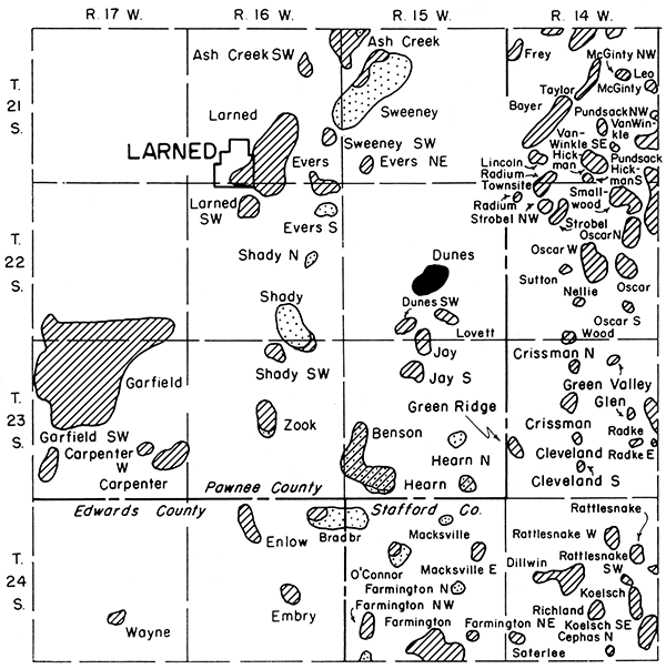
The location of the Dunes pool is shown in Figure 1. It lies in sec. 22 and 27, T. 22 S., R. 15 W., Pawnee County, Kansas, approximately 8 miles southeastward from the town of Larned and approximately 6 miles southwestward from the town of Radium.
Figure 1--Location map of the Dunes pool, Pawnee County, Kansas.
The discovery well for the Dunes pool was the Westgate-Greenland Oil Company (now Natural Gas and Oil Corp., a division of Mississippi River Fuel Corp.) No. 1 Smith, in the SE SE SW sec. 22. It was completed February 27, 1953, and had a drawdown potential of 2,822 barrels of oil per day, cut with 4 percent water, from the Arbuckle dolomite. The location of the discovery well is indicated on all maps by an arrow. So far eight wells have been completed as Arbuckle producers; there are no other producing zones in the pool, although drill-stem tests in the Lansing-Kansas City limestone at several wells were favorable. Four dry holes have been drilled, which at least partly define productive limits of the pool. Accumulative pipe line runs through March 1957 amounted to 286,542 barrels.
The surface of the area is covered by unconsolidated Quaternary sediments, which produce a flat to gently rolling topography. Underlying the Quaternary sediments are, in descending order, the Pleistocene Meade Group, consisting of sands and gravels; the Dakota, Kiowa, and Cheyenne shale and sandstone formations, of early Cretaceous age; Permian sediments consisting of approximately 2,300 feet of alternating shales and sandstones containing thin beds of anhydrite and gypsum and mudstone grading downward into salt, marine shales, and limestones; the alternating limestones and shales of Pennsylvanian age, including the limestone sequence of the Lansing-Kansas City Groups in the Missourian Series of Pennsylvanian age; a basal conglomerate, which overlies the pre-Pennsylvanian rocks; the Viola limestone, of Ordovician age; and the Simpson Group and the Arbuckle dolomite, of Ordovician or Cambro-Ordovician age.
Several pronounced unconformities occur locally in this geologic column and include those at the top of the lower Cretaceous, the top of the Permian, the top of the Pennsylvanian, the top of the Viola limestone, and the top of the Arbuckle dolomite.
The Stone Corral anhydrite, in the upper part of the Permian, affords an excellent seismic and subsurface marker in this general area. There are several other good markers, which are discussed later. Locally, the Hutchinson salt, of Permian age, will cause interpretation problems where its thickness varies markedly and rapidly. This is not a problem in the Dunes area.
The Lansing-Kansas City limestones and the Arbuckle dolomite constitute the most important reservoir rocks in this area, although Viola limestone and Simpson sandstone production can be found in some places.
Regionally, the area lies on the southwestern flank of the Central Kansas Uplift between the Rush rib and the Pawnee rib. Two dominant structural trends are present: an older, northwest-southeast regional grain, and superimposed on it the later, northeast-southwest regional anticlinal trends. The oil accumulations seem to be located on small closures on the northeast-southwest axes, at the intersection of the older arches and the younger folds, and on erosional features on the old Arbuckle dolomite surface--in some places possibly independent of true structure.
The ultimate objective of a seismic survey in this part of Kansas is to find structurally high points on which to drill test wells, frequently with reference to nearby dry holes that had encouraging shows of oil. Conventional seismic methods have not proved to be adequate for the various interpretational problems.
In Kansas, as in many other areas, most velocity difficulties and weathering correction variations exist in the first 1,000 to 2,000 feet below the surface of the ground. To handle these variables, it is possible to use a shallow horizon as a reference plane. This shallow horizon must be both a good geologic and seismic marker. By use of this shallow plane from which to measure time intervals to deeper reflecting surfaces, it is possible to map deep structure accurately. These time-interval maps allow close checks at the control wells, and anomalous areas of thinning can thus be found by reconnaissance correlation programs. Further seismic detailing, together with an occasional core hole to check the structural position of the shallow marker, will verify the indicated structure. The method is not infallible, however, and several possible sources of error are listed below:
The small amount of closure necessary to form oil or gas traps in this part of Kansas dictates an accuracy of plus or minus 5 feet in predicting the amount of relief of a structure over an associated control well. These are limits that require good subsurface data, good field operations and equipment, and good interpretational procedures. The subsurface tops in the various control wells must be obtained from electric logs, inasmuch as sample tops normally are not sufficiently accurate to be used in the process of integrating seismic and subsurface data.
Throughout central western Kansas, the Stone Corral anhydrite has proved to be suitable for use as a reference plane. Other good reflecting surfaces are the Tarkio limestone, the Topeka limestone, the Oread limestone, the Lansing Group, the Viola limestone, and the Arbuckle dolomite. Normally, maps showing the interval from the Stone Corral anhydrite to several of the deeper horizons are made to provide a check on the coincidence of structure with depth, and a check on the over-all accuracy of the survey.
Beginning in 1951 an initial reconnaissance network of correlation shotpoints was laid out and shot throughout a large part of Stafford and Pawnee Counties, including shotpoints especially placed to provide seismic tie points to the various test wells in the program area. The seismic field work and interpretation was done by Geophysical Consultants, Inc., under the complete supervision of the firm of Manhart, Millison & Beebe for the Westgate-Greenland Oil Company. Anomalous areas were closely examined and, where necessary, detail shotpoints were shot on the 10-acre or 20-acre locations to verify and outline the structure. Frequently, a core hole was drilled to determine the true structural position of the Stone Corral anhydrite with respect to the nearby control wells. The drill site for the test well was chosen on the evidence from the various interval maps.
In the area under discussion, several time-interval maps were made but only two have been prepared for this report. The best deep reflection, locally, was from the Lansing Group. A deeper reflection, which was identified merely as "pre-Pennsylvanian" at the time the program was being shot, was used to provide deep information. This interval generally checked the Lansing interval qualitatively, but many of the seismic-to-subsurface checks were less accurate than those for the Lansing interval. To handle adequately the complexities of the pre-Pennsylvanian section requires unusually careful work in most areas. The pre-Pennsylvanian usually can be worked out, however, even though the task is difficult.
Six maps (Fig. 2-7) have been prepared to show the results of geophysical and geological work in the Dunes pool area. Comparison of a conventional seismic time structure map (Fig. 2) and a structure map of the Stone Corral anhydrite (Fig. 3) will illustrate the effect of near-surface variables on conventional mapping. The 5-foot contours on the structure map compare roughly with approximately 7-foot contour intervals on the seismic time map. The seismic time map shows shifting of structure, which is extreme in many areas. The size of the structures is such that the required accuracy demands a much better definition of structure than is afforded by the seismic time maps.
Figure 2--Conventional seismic time structure map of Stone Corral anhydrite. Contour interval 2 milliseconds (approximately 7 feet). Arrow indicates discovery well.
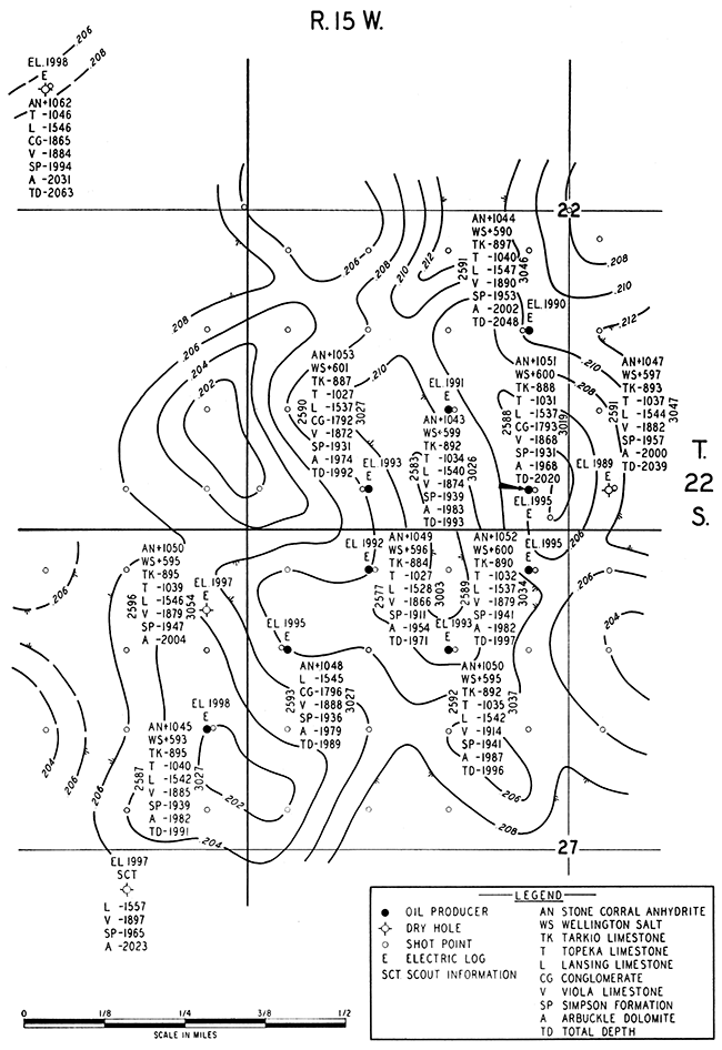
Figure 3--Structure map of Stone Corral anhydrite based on electric log tops only. Contour interval 5 feet.
The Stone Corral-Lansing time-interval map shown in Figure 4 demonstrates very satisfactory accuracy when compared with the actual intervals at the various wells. The time intervals are within approximately one millisecond (6 to 7 feet) from well to well. The general configuration of structure also is good.
Figure 4--Seismic time interval map between Stone Corral anhydrite and Lansing limestone. Contour interval 2 milliseconds (approximately 12 feet).
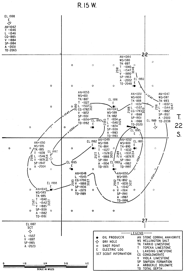
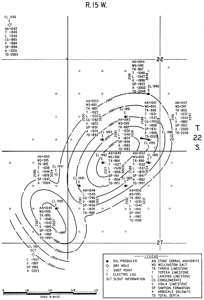
Comparison of the time-interval map between the Stone Corral and the pre-Pennsylvanian reflections (Fig. 5) with the Stone Corral-Lansing time-interval map (Fig. 4) demonstrates general coincidence of the structural features of both maps. The deeper map shows greater closure, but the seismic time intervals of the deeper map do not exhibit the accuracy of the Lansing map insofar as well ties are concerned. This discrepancy is attributed to variability of the pre-Pennsylvanian reflection in this part of Kansas.
Figure 5--Seismic time interval map between Stone Corral anhydrite and a pre-Pennsylvanian horizon. Contour interval 2 milliseconds (approximately 13 feet).
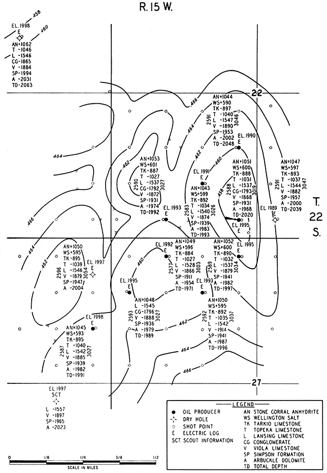
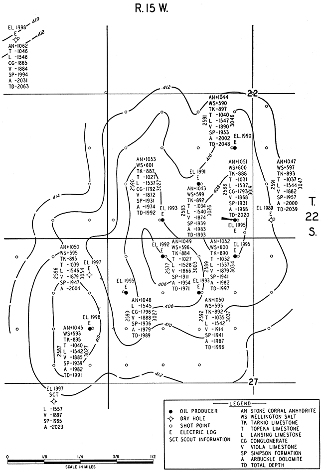
The structure map of the Arbuckle dolomite shown in Figure 7 indicates that the discovery well actually was located near the northeastern edge of the structure. According to the deeper time-interval map (Fig. 5), this location should have been structurally higher. The Lansing time-interval map (Fig. 4) predicted the best location accurately in the NE NW NW sec. 27. This point was the highest location drilled in the field and exhibited the smallest time interval. The Lansing limestone structure is shown by Figure 6.
Figure 6--Structure map of Lansing limestone based on electric log tops only. Contour interval 5 feet.
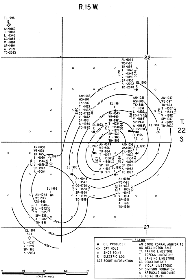
Figure 7--Structure map of Arbuckle dolomite based on electric log tops only. Contour interval 10 feet.
The reference-plane method of seismic exploration has found, and will continue to find, much oil in central western Kansas. It is an exploration tool that must be used with discretion, however, as has been pointed out in the preceding text. It can be used either for rank wildcat exploration or for determining stepout locations to known fields. Refinements, which will undoubtedly pay big dividends, will include not only improvements in instrumental and field techniques, but also a more thorough understanding of, and a willingness to work with, the reflection spectrum from the pre-Pennsylvanian rocks. A similar case history of the Smallwood pool has been discussed by Beebe and Ballou (1956) and is cited here for those who might wish to investigate this exploration procedure further.
The writer wishes to express his appreciation to Natural Gas and Oil Corporation, a division of Mississippi River Fuel Corporation, to Cities Service Oil Company, and to the former members of the now-dissolved firm of Manhart, Millison & Beebe for permission to publish this paper.
Beebe, B. W., and Ballou, A. L. (1956) Case history of the Smallwood pool, Stafford County, Kansas: Geophysical Case Histories, Soc. Expl. Geophysicists, v. 2, p. 310-327.
Kansas Geological Survey
Comments to webadmin@kgs.ku.edu
Web version Jan. 6, 2014. Original publication date 1959.
URL=http://www.kgs.ku.edu/Publications/Bulletins/137/Rupnik/index.html