| Original published in W.W. Hambleton, ed., 1959, Symposium on Geophysics in Kansas: Kansas Geological Survey, Bulletin 137, pp. 287-295 | ||
The Carter Oil Company
The complete article is available as an Acrobat PDF file.
A brief history is presented of the exploration procedure used in the discovery of the Lindsborg pool, McPherson County, Kansas, with a description of the seismic equipment and methods used to discover the anomaly. The significance of the discovery is discussed briefly.
The Lindsborg pool occupies an area of about 8 to 10 square miles in the northwestern part of T. 17 S., R. 3 W., and extends southwestward into T. 17 S., R. 4 W., McPherson County, Kansas. The pool is reported to have 99 producing wells; estimated total ultimate yield is about 14,000,000 barrels of oil. Some of the wells on the northeast flank of the field are within the limits of the town of Lindsborg.
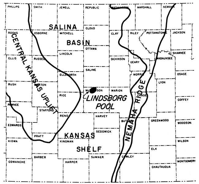
With respect to geologic province, the Lindsborg pool lies in a border position on the southern rim of the Salina Basin or on the northern rim of the Kansas Shelf or Sedgwick Basin (Fig. 1). For the purpose of this paper, it will be considered to lie in the Salina Basin, inasmuch as its discovery and later revival opened a producing trend that extends northeastward into the Salina Basin.
Figure 1--Map showing location of Lindsborg pool, McPherson County, Kansas.
Prior to 1937 no productive geophysical exploration had been conducted by anyone in the Salina Basin portion of Kansas. A few scattered wildcat tests had been drilled on known subsurface and surface trends, such as the Abilene Arch, with discouraging results. Although some activity spread into the area in 1929 and 1930 after the discovery of prolific pools to the south and southeast, this effort was limited and short-lived. During the early thirties not much exploration of any sort was carried out in this province, owing to the depression and to preoccupation of the industry with the central and western parts of the state. Discoveries such as the Richardson, Gates, Beaver, Pawnee Rock, Zenith, and Burnett pools contributed to this preoccupation. They also hastened widespread acceptance of geophysics in general, and the reflection seismograph in particular, as an exploration tool in Kansas.
On June 10, 1937, The Carter Oil Company moved Seismograph Party No. 7 into Salina, Kansas, as part of a plan of widespread seismic coverage of the Salina Basin. On the following day shooting began on an experimental basis. Well control consisted of the following dry holes that penetrated the Viola or deeper formations:
| Location | Date |
|---|---|
| SW SW SW sec. 20, T. 17 S., R. 3 W. | 1930 |
| SW SW sec. 35, T. 17 S., R. 3 W. | 1931 |
| SW SW SW sec. 8, T. 18 S., R. 3 W. | 1929 |
| NE NE SE sec. 11, T. 18 S., R. 3 W. | 1935 |
| SE NW sec. 12, T. 18 S., R. 3 W. | 1933 |
Experimental seismic shooting procedures consisted almost entirely of varying the profile spread distance, the number of geophones per channel, and the charge size and shot depth. It was also possible to shoot an unmixed circuit, the output of each geophone station seen on one trace only, or a mixed circuit, the output of varying numbers of geophone stations overlapped on each trace. These mixed circuits generally enhanced the appearance of the seismic records, but were used with misgivings by the interpreters of that day. There was, at that time, no way to change band pass filters except by rebuilding the amplifiers, because variable filter circuits were still a thing of the future for most operators. Hence, practical limits to experimentation were soon reached.
Widely separated holes were used for the experimental work and were located so as to provide a wide range in surface conditions. Results indicated that fair to good records generally could be obtained from shot-holes in the Ninnescah and Wellington shales, which crop out above Recent alluvial deposits of Smoky Hill River. Shot holes were drilled to depths of less than 100 feet, and small charges of dynamite, averaging about one pound, were used.
Good records were difficult to obtain at locations in the alluvium-filled meander belt of the river. It was impossible to judge whether a hole would require one-sixteenth or several pounds of dynamite to obtain a usable record; ground roll frequently was sufficiently strong to spoil a record; and it was difficult to keep shot holes open in alluvium.
Experimental shooting showed that a single end, in-line geophone spread of 200 to 450 feet, including six geophone stations separated by 50-foot intervals, provided the optimum spread arrangement. The shooting pattern included one correlation point per mile and each point was shot in two and sometimes three or four different directions. An average of the reflection times from these directions was used to calculate depth.
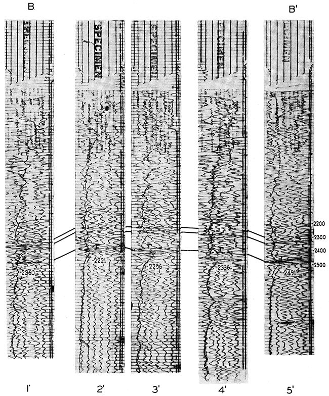
The instruments included a mirror galvanometer type camera, which provided black traces on a white background (Fig. 2). This was in contrast to older types of string cameras, which produced partly white traces on a dark-gray background. A watch mechanism was built into this camera, which provided a time check with a photographic record of the balance wheel movement. This time line can be seen near the top of the records. The trace that moves erratically from near the center of the record toward the bottom (or left side in the cross section arrangement) is a reflection amplitude indicator trace.
Figure 2--Seismic record section across Lindsborg pool. Locations are shown on line B-B', Fig. 4. Vertical scale applicable only to deepest event.
The six reflection channels, plus one spare, had four-stage amplifiers. In addition, this set of instruments had a trigger type expander, which increased amplifier sensitivity from a low value for early reflections to a high value for deep reflections. The geophones were a low-impedance oil-damped type. Magnetically damped types were not yet generally in use. Only one geophone per trace was used in obtaining records.
The relative simplicity of field party operations resulted in fairly high record production, which, together with the sparse pattern of control, made it possible to cover a sizeable territory in a short time. By the end of July 1937, the subject area had been shot and mapped.
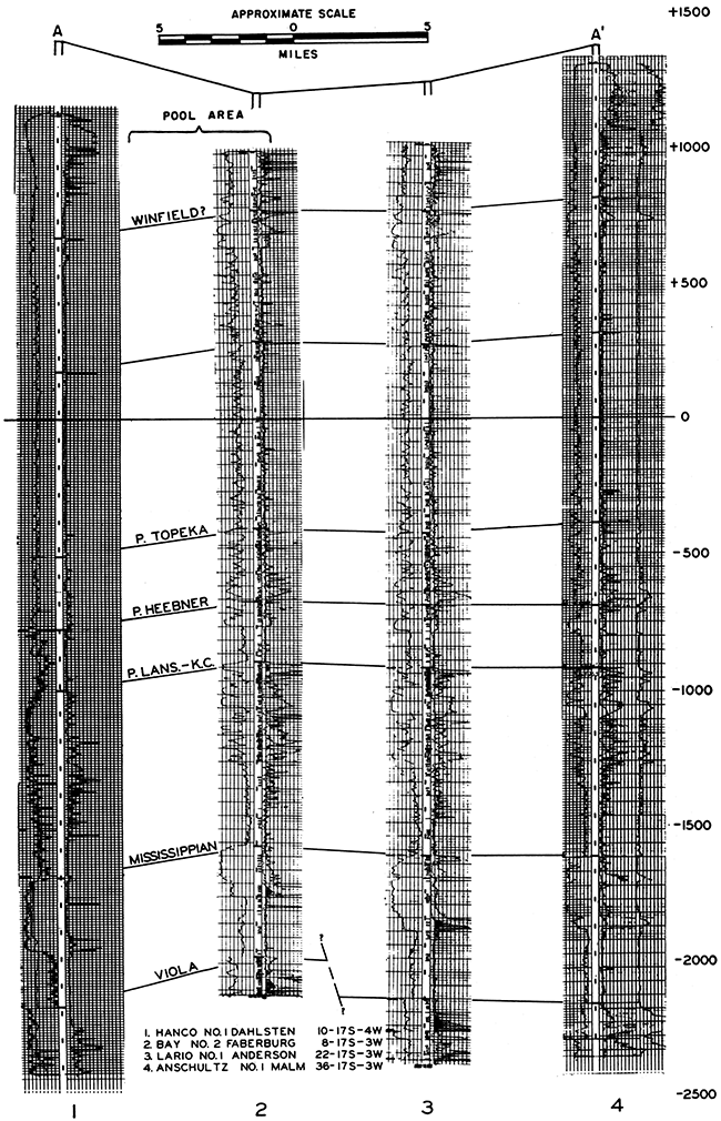
Representative results of shooting in the Lindsborg pool area are shown in the seismic record cross section of Figure 2 (locations shown in Fig. 4). Although these unmixed records seem primitive by modern standards, they, and the instruments that obtained them, were more than up-to-date for that time. For purposes of comparison, an electric log cross section is shown in Figure 3 (locations shown in Fig. 5).
Figure 3--Electric log section across Lindsborg pool. Locations are shown on line A-A', Fig. 5.
The seismic map shown in Figure 4 has been traced from one of the field report maps of the time. No attempt has been made to alter the interpretation. The data on which these contours were based were derived by simple calculations. The deepest shot in each hole was assumed to be safely below the low-velocity layer, and each record taken from any given hole was corrected to the deepest shot level. This correction was made by subtracting the uphole time (time from shot to surface) of the deepest shot from the reflection time, calculating the depth to the reflector, and from this depth subtracting the elevation of the deepest shot to obtain the sub-sea datum.
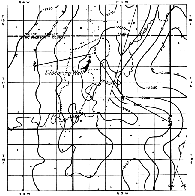
Figure 4--Seismic contour map on "Trenton" (Viola) reflections, Lindsborg pool area. Contour interval 50 feet. Line B-B' shows location of seismic record section, Fig. 2.
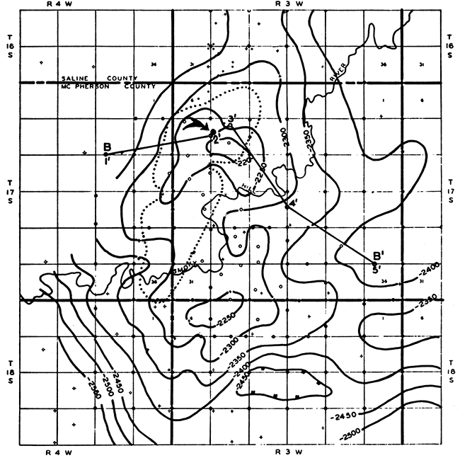
The effectiveness of this method can be seen by comparing the seismic map (Fig. 4) and geologic map of the Viola (Fig. 5). Although the two maps agree in general, some distortion of seismic contours is evident. The seismic contours show exaggerated west and southwest dip in the western part of the area. This exaggerated dip is doubtless caused by the low velocity effect of thick unconsolidated surface material filling McPherson channel, a deeply buried, stream-cut channel incised in older deposits in the western part of the McPherson Valley (Lohman, 1942). This channel probably continues almost due south, its axis lying just east of the center line of R. 4 W.
Figure 5--Geologic contour map on top of Viola limestone, Lindsborg pool area. Contour interval 50 feet. Line A-A' shows location of electric log section, Fig. 3.
Another possible cause of distortion of seismic contours is the velocity effect of the Hutchinson (Wellington) salt. The eastern edge of this high-velocity deposit is generally considered to be the McPherson channel, and a thin bed of salt can be identified at the very top of the electric log in Well No. 1 on the electric log cross section (Fig. 3). It is known that insular deposits of salt east of the McPherson channel occasionally affect calculated seismic depths and exaggerate the calculated relief if corrections are not made.
Despite the velocity distortions, the structural high was located at its correct geographical position and the stage was set for the pool discovery. Available acreage was acquired during the last half of 1937, and the Carter No. 1 E. Hoglund in the C W2 SW NW sec. 8, T. 17 S., R. 3 W., was staked early in November of that year. Meanwhile Seismograph Party No. 7 continued its assigned exploration program elsewhere in the Basin. The No. 1 Hoglund was completed February 2, 1938, as a producing well having a potential of 345 barrels of 36°-gravity oil and an estimated 50 barrels of water per day from the Viola. Shows also were logged in the Simpson, which was later to become a producing zone. The hole was drilled to the Arbuckle, or "Siliceous lime" as it was frequently called. The Arbuckle was tested and was water bearing. After the completion of the discovery well, additional seismic points were added in its vicinity. These points merely confirmed previous work and no change was made on the map.
The Archer and Crane No. 1 Templin, a dry hole in the NW SW SE sec. 32, T. 17 S., R. 3 W., was started November 23, 1937, almost contemporaneously with the No. 1 Hoglund with The Carter Oil Company support. It was abandoned March 9, 1938, after reporting shows in the Viola and Arbuckle. The well was low structurally and is perhaps situated on the downthrown side of a fault.
A new wave of activity in the southern part of the Salina Basin was started in July 1942, after completion of the Auto Ordnance No. 1 Johnson well in the C W2 SW NE sec. 8, T. 17 S., R. 3 W. This well opened production from the Simpson dolomite. This new producing zone discovery, however, was a postscript to the most significant aspects of the original Lindsborg discovery. The first aspect was the probability that there were other accumulations of oil in the Salina Basin. The second was that it was possible to discover these accumulations by seismic surveys. The third was that the oil industry became aware of these facts, and additional discoveries to the north followed.
Grateful acknowledgment is expressed to The Carter Oil Company for permission to release the material presented in this paper. The author also is indebted to colleagues within the Company for their kind assistance and suggestions, particularly to Mr. J. B. Coffman, Kansas District Geologist and Coordinator, and to Mr. S. R. Marsh, now Southern Division Geophysicist and former Observer on Carter Seismograph Crew No. 7.
Lohman, S. W. (1942) Ground-water supplies available for national defense industries in south-central Kansas: Kansas Geol. Survey, Bull. 41, pt. 1, p. 1-20. [available online]
Kansas Geological Survey
Comments to webadmin@kgs.ku.edu
Web version Jan. 6, 2014. Original publication date 1959.
URL=http://www.kgs.ku.edu/Publications/Bulletins/137/Brewer2/index.html