Kansas Geological Survey, Bulletin 134, Part 2, originally published in 1959
Originally published in 1959 as Kansas Geological Survey Bulletin 134, Part 2. This is, in general, the original text as published. The information has not been updated. An Acrobat PDF version (4 MB) is also available.
The supply and utilization of Kansas mineral resources for cement raw materials are discussed. Specifications of the types of portland cement are briefly described. A brief summary of fuel, transportation, power, and market factors is included.
All of the eastern one-third and much of central Kansas has abundant rock suitable for manufacture of portland cement. A diversified market for portland cement presently exists. Bulk transportation by truck in a north-south direction has not been fully utilized in Kansas. The recent development of a small vertical-kiln type of cement plant, which requires only about a twentieth of the investment needed for a conventional plant, could facilitate additional cement production in Kansas.
Numerous requests for information as to the availability of cement raw materials in various parts of Kansas prompted preparation of this report, which summarizes data on classification and distribution of cement raw materials in the state. Systematic study of Kansas mineral resources by the State Geological Survey has provided the geological and chemical information for the report.
An excellent study by Warne (1955) reviews the history of the Kansas cement industry and presents data on price, cost, and investment. There have been significant changes in the cement industry since 1955, however, and the present report complements Warne's study.
A growing, dispersed, and diversified market, stimulated by new uses and expansion of established uses, is in evidence. The ready-mixed concrete industry expanded during the middle 1950's, and the ready-mixed concrete supplier has become a recognized local business. In addition, the manufacture of block (both dense and light weight) increased markedly after World War II. These industries are finding a market in city paving, residential construction, and industrial construction where the advantages of uniform mixing and proportioning and good timing eliminate the need for on-the-job mixing of the different materials necessary for good concrete. Another growing industry is the production of pre-stressed concrete structural units such as large beams for bridges. The great weight of many of these units suggests that fabrication should take place near the place of use, and that plants should disperse into areas of consumption. A third source of growth in the cement industry is the use of cement by oil field drilling and service companies. The oil industry cannot select convenient areas, but must go where the geologic facts indicate oil. This growing market is now dispersed beyond the normal shipping range of many of the permanent-type cement plants.
Highway construction will consume more cement in many areas of the state during the next few years as the interstate highway program develops. Where feasible, as in eastern Kansas, concrete is being used for the highway itself, but in all parts of the state, bridges, culverts, and other structures will be constructed of concrete.
The prospect of a growing, dispersed, and diversified market for cement introduces a new factor in location for the cement industry. The dispersed market can be better served by more effective transportation and by development of widely dispersed small cement plants. In Kansas, rail transportation is excellent in an east-west direction, but does not lend itself to north-south delivery. Truck transportation of bulk cement has not yet been exploited effectively and may provide the element of effective transportation. New cement plants have not developed concurrently with the new markets, because of the large initial capital investment necessary and the strongly competitive nature of nonmetallic industry. Recent developments in cement manufacturing equipment may reduce initial cost and stimulate new business ventures that have good chance for success if they are soundly studied beforehand and well managed.
Interest in the small cement plant was revived in December of 1956 by an article concerning a Swiss-manufactured vertical kiln (Hughes, 1956). This type of small plant will produce a minimum of 150,000 barrels of cement (376 lb. per bbl.) per kiln per year. The average American plant produces about 2 to 2 1/2 million bbl. per year. The initial investment for the small plant described in the article is about $1,000,000, or 1/10 to 1/20 the cost of the conventional plant.
This small plant operates on the principle of nodulization of powdered raw materials in a continuous circuit, the nodules being fed into the top of the vertical kiln. Outside the United States, the fuel most used is anthracite coal or coke. The fuel is blended into the feed, hence the vertical kiln is much more efficient. than the rotary kiln. Adaptation to petroleum fuels is feasible. This small plant could meet the needs of a dispersed market and it does not require the large initial investment of the conventional type of plant. Furthermore, the chalky and marly carbonate rocks found in the western part of Kansas are especially suitable for the nodulized feed technique.
The word "cement" is synonymous with portland cement throughout the United States. The American Society for Testing Materials (A. S. T. M. Spec., 1955) defines portland cement as "the product obtained by pulverizing clinker consisting essentially of hydraulic calcium silicates, to which no additions have been made subsequent to calcination other than water and/or untreated calcium sulfate, except that additions not to exceed 1.0% of other materials may be interground with the clinker at the option of the manufacturer, provided such materials in the amounts indicated have been shown to be not harmful by tests carried out or reviewed by Committee C-1 on cement."
There are many cements other than portland cement; two common cements in the United States are natural cement and sorel cement. Natural cement is made by heating argillaceous limestone until the carbon dioxide is evolved. This cement reacts slowly but hardens to a reasonable strength. It continues to grow stronger for many years. Natural cement was used widely before portland cement came onto the market. There are still several plants producing natural cement for masonry cement and for blending with portland cement where conditions require special properties. Sorel cement is a special cement composed of magnesium oxychloride (3 MgO · MgCl2 · 11 H2O) and made by mixing approximtaely 20 percent of magnesia (MgO) with a solution of magnesium chloride. The product is useful only for binding dry materials, as it cannot be used in the presence of water. Gypsum is also used for special cements; plaster-of-paris is known to everyone. Keene's cement and Parian cement also are made by processing gypsum. In Europe, several other cements are made, usually from the byproducts of other industries. Examples are portland slag cement, pozzolana cement, iron ore cement, and waste aluminum ore called bauxitland cement. For a more detailed account of the history and origin of cements, consult Witt (1947) and Bogue (1947).
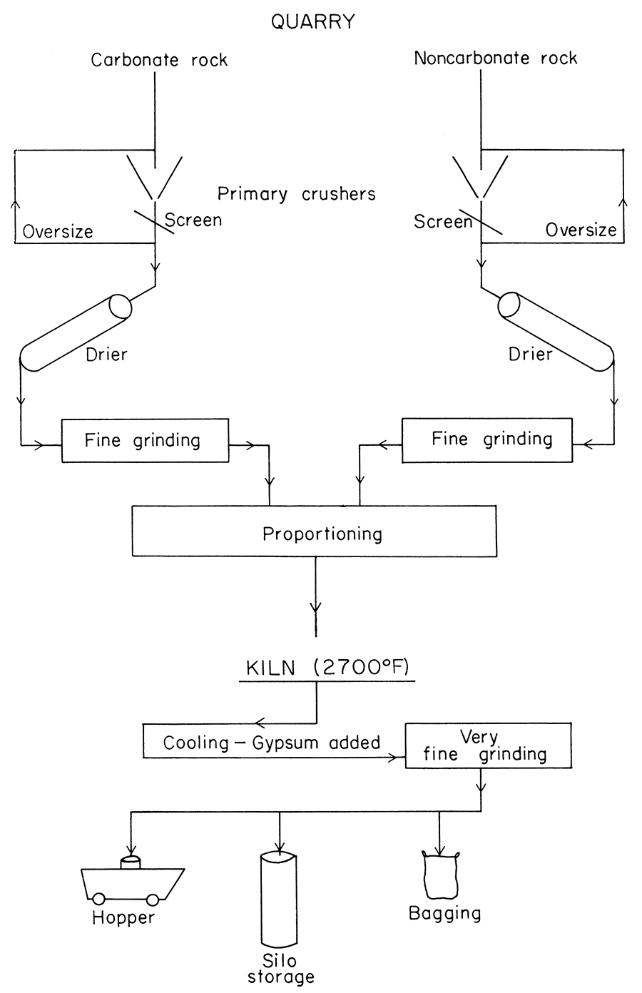
Portland cement is made by pulverizing materials composed chiefly of calcium and aluminum compounds and silica, at a temperature of about 2700° F. At this high temperature, the raw materials react with each other to form calcium silicates, having specific compositions and physical properties that are called cementaceous; that is, they become hard and rigid by reacting slowly with water. The hard clinker formed by the burning must be pulverized to a very small grain size as the final step of the process. A simplified flow-sheet, illustrating the manufacturing process, is shown in Figure 1. The raw materials can be of several different types but usually are the materials that are most plentiful and inexpensive. Limestone is the most widely used source of calcium. Sea shells, blast furnace slag, and other sources of calcium can be used. Likewise, shale is the most widely used source of silica and alumina; other sources (clays, slags, igneous and metamorphic rocks, and sandstones) are used where necessary or more profitable.
Figure 1—Simplified flow sheet, illustrating the manufacturing process of portland cement.
The producer of portland cement faces complex specifications and requirements (A. S. T. M., 1955). Five types of portland cement are recognized (Table 1). For each of the five types there are chemical, mineralogical, and physical specifications; Table 2 lists the chemical and mineralogical requirements, and Table 3 sets forth the physical tests and values demanded for portland cement.
Table 1—Types of portland cement (A. S. T. M., 1955).
| Type I: | For use in general concrete construction where the special properties specified for types II, III, IV, and V are not required. |
| Type II: | For use in general concrete construction exposed to moderate sulfate action, or where moderate heat of hydration is required. |
| Type III: | For use when high early strength is required. |
| Type IV: | For use when a low heat of hydration is required. |
| Type V: | For use when high sulfate resistance is required. |
Table 2—Chemical requirements of portland cement (A. S. T. M., 1955).
| Type I |
Type II |
Type III |
Type IVa |
Type Va |
||
|---|---|---|---|---|---|---|
| Silicon dioxide (SiO2) min. % | 21.0 | |||||
| Aluminum oxide (Al2O3) max. % | 6.0 | b | ||||
| Ferric oxide (Fe2O3) max. % | 6.0 | 6.5 | b | |||
| Magnesium oxide (MgO) max. % | 5.0 | 5.0 | 5.0 | 5.0 | 4.0 | |
| Sulfur trioxide (SO3): When 3CaO · Al2O3 is 8% or less (max. %) | 2.5 | 2.5 | 3.0 | 2.3 | 2.3 | |
| When 3 CaO · Al2O3 is more than 8% (max. %) | 3.0 | 3.0 | ||||
| Loss on ignition, max. % | 3.0 | 3.0 | 3.0 | 2.3 | 3.0 | |
| Insoluble residue, max. % | 0.75 | 0.75 | 0.75 | 0.75 | 0.75 | |
| Tricalcium silicate: (3CaO · SiO2)c, max. % | 50 | 35 | 50 | |||
| Dicalcium silicate: (2CaO · SiO2)c, min. % | 40 | |||||
| Tricalcium aluminate: (3CaO · Al2O3)c, max. % | 8 | 15 | 7 | 5 | ||
| a Not normally kept in stock. b Tricalcium aluminate shall not exceed 5 percent, and tetracalcium aluminoferrite (4CaO · Al2O3 · Fe2O3) plus twice the amount of tricalcium aluminate shall not exceed 20 percent. c The expressing of chemical limitations by means of calculated assumed compounds does not necessarily mean that the oxides are actually or entirely present as such compounds. The percentages of tricalcium silicate, dicalcium silicate, tricalcium aluminate, and tetra calcium aluminoferrite shall be calculated from the chemical analysis as follows: Tricalcium silicate = (4.07 X percent CaO) - (7.60 X percent SiO2) - (6.72 X percent Al2O3) - (1.43 X percent Fe2O3) - (2.85 X percent SOa) Dicalcium silicate = (2.87 X percent SiO2) - (0.754 X percent 3CaO · SiO2) Tricalcium aluminate = (2.65 X percent Al2O3) - (1.69 X percent Fe2O3) Tetracalcium aluminoferrite = 3.04 X percent Fe2O3 Oxide determinations calculated to the nearest 0.1 percent shall be used in the calculations. Compound percentages shall be calculated to the nearest 0.1 percent and reported to the nearest 1 percent. |
||||||
Table 3—Physical requirements of portland cement (A. S. T. M., 1955).
| Type I |
Type II |
Type III |
Type IVa |
Type Va |
|||
|---|---|---|---|---|---|---|---|
| Fineness, specific surface, sq. cm. per g. (alternate methods): b | |||||||
| Turbidimeter test: | |||||||
| Average value, min. | 1600 | 1700 | 1800 | 1800 | |||
| Minimum value, anyone sample | 1500 | 1600 | 1700 | 1700 | |||
| Air permeability test: | |||||||
| Average value, min. | 2800 | 3000 | 3200 | 3200 | |||
| Minimum value, anyone sample | 2600 | 2800 | 3000 | 3000 | |||
| Soundness: | |||||||
| Autoclave expansion, max. percent | 0.50 | 0.50 | 0.50 | 0.50 | 0.50 | ||
| Time of setting (alternate methods):c | |||||||
| Gillmore test: | |||||||
| Initial set, min., not less than | 60 | 60 | 60 | 60 | 60 | ||
| Final set, hr., not more than | 10 | 10 | 10 | 10 | 10 | ||
| Vicat test (Method C 191): | |||||||
| Set, min., not less than | 45 | 45 | 45 | 45 | 45 | ||
| Air content of mortar, prepared and tested in accordance with Method C 185, max., percent by volume, less than | 12.0 | 12.0 | 12.0 | 12.0 | 12.0 | ||
| Compressive strength, psi.:d | |||||||
| The compressive strength of mortar cubes, composed of 1 part cement and 2.75 parts graded standard sand, by weight, prepared and tested in accordance with Method C 109, shall be equal to or higher than the values specified for the ages indicated below. | |||||||
| 1 day in moist air | 1700 | ||||||
| 1 day in moist air, 2 days in water | 1200 | 1000 | 3000 | ||||
| 1 day in moist air, 6 days in water | 2100 | 1800 | 800 | 1500 | |||
| 1 day in moist air, 27 days in water | 3500 | 3500 | 2000 | 3000 | |||
| Tensile strength, psi.: d | |||||||
| The tensile strength of mortar briquets composed of 1 part cement and 3 parts standard sand, by weight, prepared and tested in accordance with Method C 190, shall be equal to or higher than the values specified for the ages indicated below: | |||||||
| 1 day in moist air | 275 | ||||||
| 1 day in moist air, 2 days in water | 150 | 125 | 375 | ||||
| 1 day in moist air, 6 days in water | 275 | 250 | 175 | 250 | |||
| 1 day in moist air, 27 days in water | 350 | 325 | d | 300 | 325 | ||
| a Not normally kept in stock. b Either of the two alternate fineness methods may be used at the' option of the testing laboratory. However, in case of dispute, or when the sample fails to meet the requirements of the Blaine meter, the Wagner turbidimeter shall be used, and the requirements in Table III for this method shall govern. c The purchaser should specify the type of setting time test required. In case he does not so specify, or in case of dispute, the requirement of the Vicat test only shall govern. d The purchaser should specify the type of strength test required. In case he does not so specify, the requirements of the tensile strength test only shall govern. The strength at any age shall be higher than the strength at the next preceding age. Unless otherwise specified, the compressive and tensile strength tests for types I and II cement will be made only at 3 and 7 days. If, at the option of the purchaser, a 7-day test is required on Type III cement, the strength at 7 days shall be higher than at 3 days. |
|||||||
After considering the many specifications in effect, one must further consider the problem of blending raw materials so that a desired or required composition is obtained.
Burned limestone will lose 35 to 44 percent of its raw weight as carbon dioxide and moisture. The calculations for a raw mix must take this fact into account. A rough proportion of 80 percent limestone and 20 percent shale or other non-carbonate material often is used as an approximate raw mix; of course, the actual chemical analysis of each material must be used to determine the final proportion. Because most natural rock deposits contain impurities and small percentages of minor elements, the final calculations become somewhat involved. As an example of the composition of limestone, the average of 325 limestone analyses from Kansas (Runnels and Schleicher, 1956) is shown:
| Compound | Wt. % | Oxide | Wt. % |
|---|---|---|---|
| Calcium carbonate (CaCO3) | 87.89 | CaO | 49.24 |
| Magnesium carbonate (MgCO3) | 3.76 | MgO | 1.62 |
| Silica (SiO2) | 6.09 | SiO2 | 6.09 |
| Alumina (Al2O3) | 1.16 | Al2O3 | 1.16 |
| Total iron as ferric oxide (Fe2O3) | 1.14 | Fe2O3 | 1.14 |
| Carbon dioxide (CO2) | CO2 | 40.42 | |
| Undetermined oxides | 0.67 |
Shales and clays contain even more minor constituents than limestone. For example, the average composition of 78 shales (Rankama and Sahama, 1950) is given below:
| Compound | Wt. % of Oxide |
|---|---|
| Silica (SiO2) | 58.38 |
| Alumina (Al2O3) | 15.47 |
| Total iron as ferrous oxide (FeO) | 6.07 |
| Magnesium oxide (MgO) | 2.45 |
| Calcium oxide (CaO) | 3.12 |
| Sodium oxide (Na2O) | 1.31 |
| Potassium oxide (K2O) | 3.25 |
| Water of hydration (H2O) | 5.02 |
| Carbon dioxide (CO2) | 2.64 |
| Unreported oxides | 2.29 |
The proportions of the constituents vary from one deposit to another. The oxides other than silica and alumina differ markedly in different deposits.
The examples of limestone and shale given above demonstrate the complexity of natural deposits that must be used to obtain a product of precise composition. After evolving the carbon dioxide as a gas, the example of limestone shown above has a composition as follows:
| Oxide | Wt. % |
|---|---|
| CaO | 82.64 |
| MgO | 2.72 |
| SiO2 | 10.22 |
| Al2O3 | 1.94 |
| Fe2O3 | 1.91 |
| 99.33 | |
| Undetermined difference | 0.67 |
| 100.00 |
Similarly, after evolving carbon dioxide and water, the composition of the example of shale is:
| Oxide | Wt. % |
|---|---|
| SiO | 63.24 |
| Al2O3 | 16.76 |
| FeO | 6.57 |
| MgO | 2.65 |
| CaO | 3.38 |
| Na2O | 1.42 |
| K2O | 3.52 |
| Unreported | 2.48 |
| 100.02 |
Preliminary calculations may be based on the rough proportion of 80 percent limestone and 20 percent shale. Each compound must be computed for both limestone and shale, according to the percentage present, as follows:
| Compound | Limestone | Shale | Wt. % of oxide in cement | ||
|---|---|---|---|---|---|
| CaO | 82.64 X .8 | + | 3.38 X .2 | = | 66.11 + .68 = 66.79 |
| SiO2 | 10.22 X .8 | + | 63.24 X .2 | = | 8.18 + 12.65 = .20.83 |
| Al2O3 | 1.94 X .8 | + | 16.76 X .2 | = | 1.55 + 3.35 = 4.90 |
| Fe2O3 | 1.91 X .8 | + | 6.57/.7 X .2 | = | 1.53 + 1.88 = 3.41 |
| MgO | 2.72 X .8 | + | 2.65 X .2 | = | 2.18 + 0.53 = 2.71 |
| Na2O | 0 | + | 1.42 X .2 | = | 0 + 0.28 = 0.28 |
The resultant figures are within the accepted range for portland cement. Because the relative percentages of limestone and shale were set arbitrarily, they should not be expected to produce the optimum values for finished cement. Various analyses of finished portland cement have the range of chemical compositions shown below:
| Compound | Wt. % |
|---|---|
| Silica (SiO2) | 20-25 |
| Alumina (Al2O3) | 3-6 |
| Ferric oxide (Fe2O3) | 0.5-6 |
| Calcium oxide (CaO) | 62-65 |
| Magnesium oxide (MgO) | 1-5 |
| Sulfur trioxide (SO3) | 0.9-1.4 |
| Loss on ignition | 0.9-1.4 |
| Acid insoluble | 0.1-0.2 |
It is also evident that in the given example the magnesium is within the range shown for finished cements (5.0 percent MgO). The K2O normally is at least partly volatilized during the firing process and hence does not enter into the calculations.
The calculations serve to demonstrate that the noncarbonate portion has much less effect than limestone upon the finished cement as far as magnesium and sodium are concerned, because a relatively small proportion is required. The calculations also demonstrate, however, that the magnesium and sodium content must be extremely low in the raw limestone portion. Because calcium oxide is the predominant compound, limestone must be used for most cements. Silica and alumina can be supplied by sand, sandstone, loess, or clay; hence, an operator has a choice of materials other than shale in blending noncarbonate portions.
The previous paragraphs illustrate the specifications for finished cement and show general composition of the raw materials before blending and firing in the kiln. It is emphasized that only four major compounds are identified in cement clinker: tricalcium silicate, 3CaO · SiO2; dicalcium silicate, 2CaO · SiO2; tricalcium aluminate, 3CaO · Al2O3; and tetracalcium aluminoferrite, 4CaO · Al2O3 · Fe2O3. The first three compounds are specifically mentioned in the specifications and are regarded as having critical maximum or minimum values. The tetracalcium aluminoferrite is not limited in the specifications. Its value lies in the fact that the iron combines with part of the alumina, thereby reducing the percentage of tricalcium aluminate-a compound that has maximum limitations (Table 1). All other elements present in the raw materials are at best mere diluents. Some, such as magnesium and the alkali elements potassium and sodium (some consumer specifications allow a maximum of 0.6 percent, figured as sodium oxide), are deleterious because of reactions that take place long after the concrete is poured. Inasmuch as gypsum (CaSO4 · 2H2O) is added after the clinker is burned (to inhibit quick setting), and there is an upper limit to the percent of sulfate allowed in the finished cement, natural sulfate in the raw materials is undesirable. Phosphate is another compound that is regarded as undesirable, whereas titanium is normally thought of merely as a diluent. The very small percentages of strontium, barium, vanadium, zirconium, and manganese in the raw materials are not taken into direct consideration.
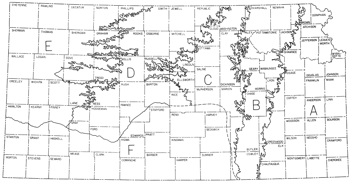
The distribution of cement raw materials in Kansas is shown by zones in Figure 2. The zones correspond generally to geologic provinces of the state and facilitate the description of cement raw materials. The Geological Survey can supply or obtain more detailed data on local areas in response to specific requests.
Figure 2—Distribution of cement raw materials in Kansas by zones.
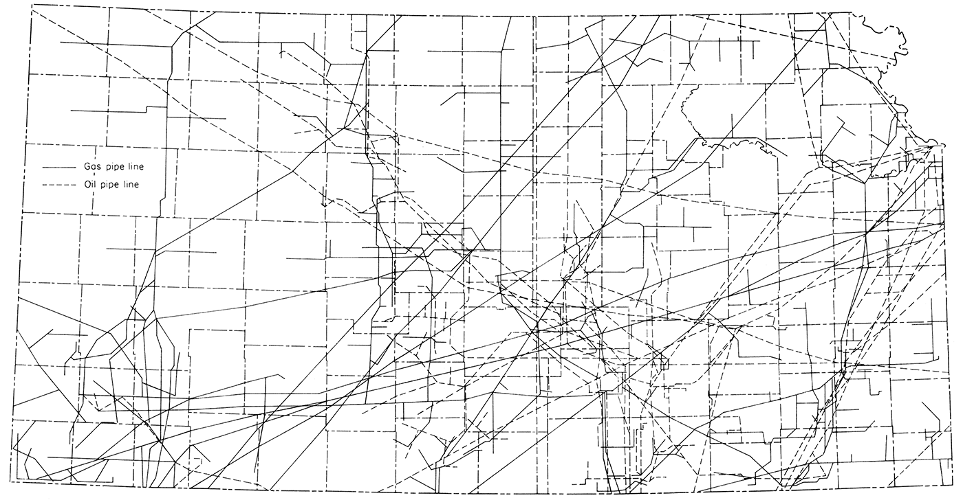
Transportation and fuel are so closely allied with raw materials for successful cement manufacture that maps showing railroads and pipelines in the state (Fig. 3 and 4) are included. Highway construction and alteration are so rapid that a map of any given date will not long remain accurate. The State Highway Commission provides up-to-date highway maps periodically.
Figure 3—Railroad lines in Kansas, adapted from Kansas Industrial Resources (K.I.D.C., 1956, p. 5).
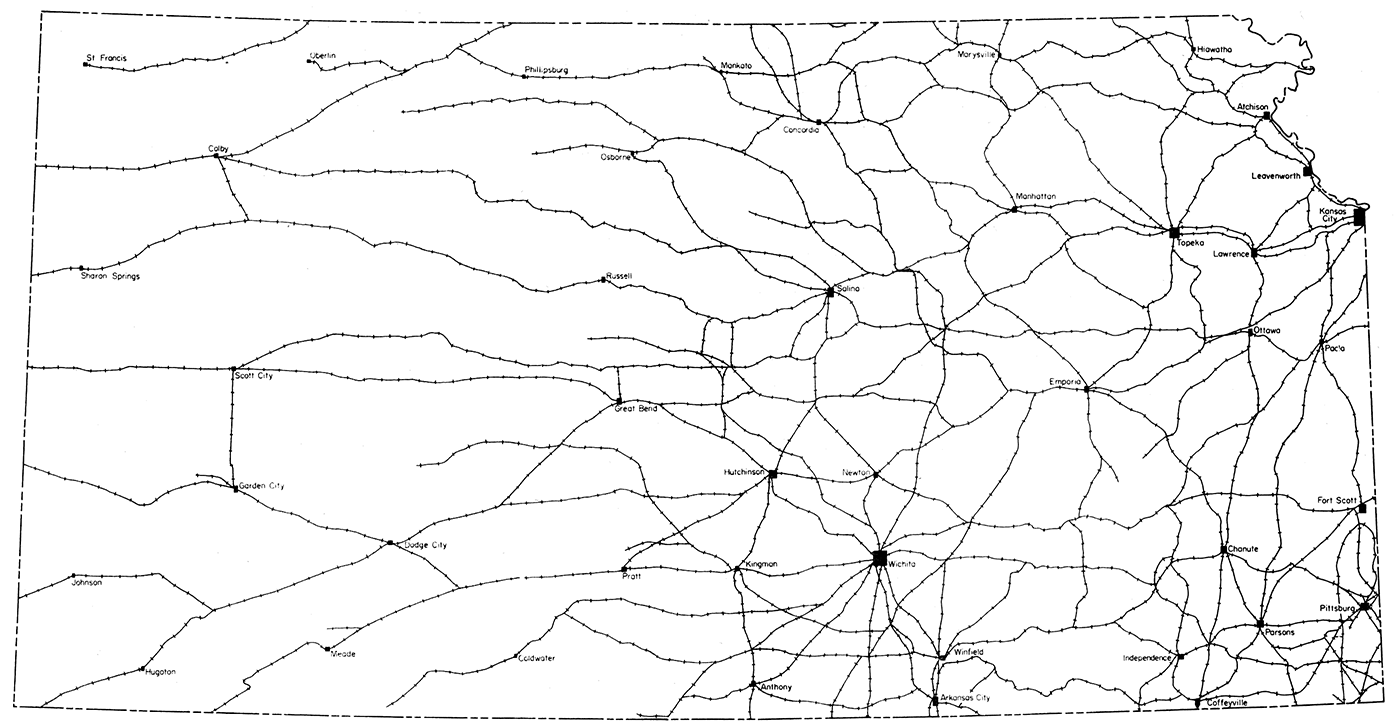
Figure 4—Pipelines in Kansas, oil and natural gas, adapted from Kansas Geological Survey Oil and Gas Investigations 18 (Goebel, 1958).
Electric power is a major item of cost in operation of any cement plant, because of the requirement for grinding of raw materials and clinker. In general, electric power cost and availability should be investigated by a prospective producer during the initial phases of study of a specific area.
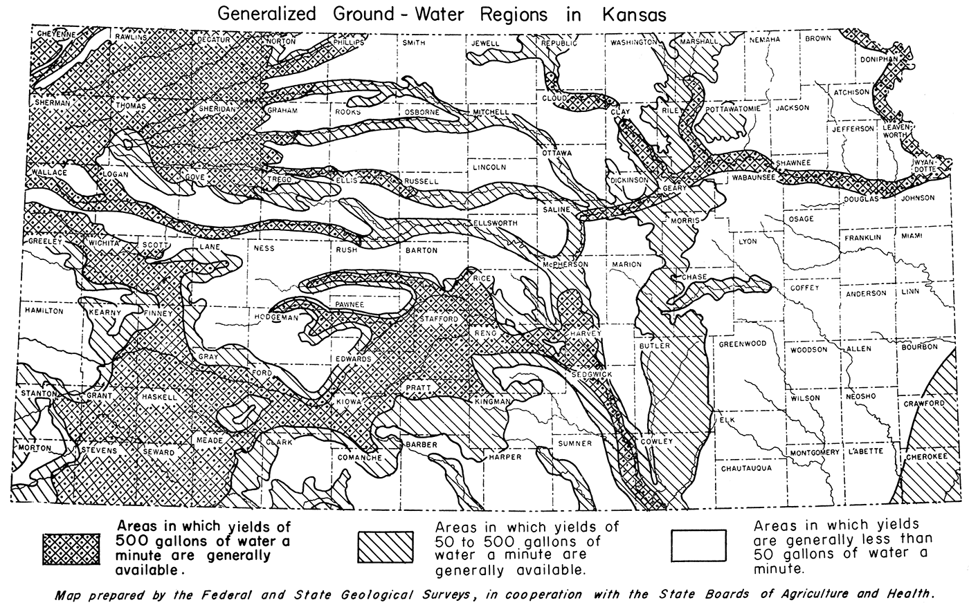
Availability of adequate supplies of water must be studied for each potential plant site. Figure 5 shows generalized occurrence and availability of ground water in the state. In addition, rivers and creeks can supply surface water in many areas.
Figure 5—Generalized occurrence and availability of ground water in Kansas, adapted from map prepared by the Federal and State Geological Surveys, in cooperation with the State Board of Agriculture and Board of Health.
This portion of the state contains rocks of Pennsylvanian age. These rocks exhibit cyclic sedimentation, that is, repeated sequences of rocks and depositional characteristics. Limestone and shale predominate, but sandstone and thin coal beds occur in many of the cycles. Much of the zone has more than adequate limestone for almost any size cement plant. Limestone is sparse in the extreme south-eastern part of the zone, especially in Cherokee and Crawford Counties. In general, westward from Topeka, shale occupies a large percentage of the total section, but limestone is adequate in most localities. Calcareous shales would' supplement the reserves of limestone. In approximately ten percent of the localities sampled, the magnesium (dolomitic) content of the limestone is too high for cement.
This zone contains all the operating cement plants in Kansas. The natural cement plant at Ft. Scott (Ft. Scott Hydraulic Cement Company) has been in continuous operation since 1868. Six portland cement companies have been operating since the early 1900's. A seventh plant was dismantled in the 1930's. All the operating plants utilize limestone and shale but add small amounts of river silt, quarry overburden, or mill scale (for iron content), when necessary for adjustment of the feed or when making other than Type I cement.
Areas along the rivers and larger creeks all are potential sites for cement manufacture if other economic factors are favorable. Barge transportation on Missouri River makes the northeast part of the zone worthy of note. Ground water is not available in adequate quantity in much of the zone, but numerous streams and rivers can supply water.
This zone includes rocks of Permian age, which are similar to the rocks of zone A in that they exhibit cyclic deposition, but differ in that the shales are thicker, the limestones less pure, and the coal beds very thin and sparse. The limestones have about the same magnesium content as those in zone A; about 10 percent of the samples contain too much magnesium for cement. The few limestone members that are dolomitic are excluded from consideration. This zone differs from zone A in that the shales show a wider range in composition; that is, more of the Permian shales are calcareous or dolomitic. Where calcareous, they offer the possibility of being almost a natural raw mix, but where they are dolomitic the magnesium content is prohibitive.
Several limestone beds have possibilities for utilization as natural mix for cement. The best known is the Ft. Riley member of the Barneston Limestone. This thick bed crops out from the Oklahoma border to the Nebraska border and is very thick from the Oklahoma border north to Manhattan. In many locations it contains 80 percent calcium carbonate and 20 percent shale or clay. At one or two locations it contains dolomitic zones. The Towanda Limestone and the Cresswell Limestone member of the Winfield Limestone crop out west of the Ft. Riley outcrop over much of the zone from south to north and are nearly the right proportion for cement raw feed.
Although in places the limestone beds contain chert, at many localities the limestone is soft and relatively easily pulverized. In some places the clayey limestone is soft enough to be termed marl.
In both zone A and zone B, river sand is available as a source of silica and alumina. To avoid costly grinding, silt sizes and fines should be used. Loess is also abundant in the northern half of both zones. This material has desirable proportions of silica and alumina, but sodium, potassium, and magnesium may be excessive for some blends. Detailed analyses of the loess deposits are available (Frye and others, 1949).
This zone does not have materials that contain enough calcium carbonate for cement manufacture. The rocks are the Dakota Formation (Cretaceous) and consist almost entirely of clay and sandstone. The clays are used extensively for brick and tile production. It is possible that some clay or iron-cemented sandstone might be utilized as a special material for cement manufacture by a plant in either zone B or zone D located within shipping distance.
This zone has about the same areal extent as zone A or zone B and contains some of the least studied strata in Kansas. Cretaceous rocks that crop out are more than 1,000 feet thick and include chalk, shaly chalk, chalky shale, and noncalcareous shale. There are immense areas of chalky shale adequate to supply any size of cement plant for many years. Only a few chemical analyses are available of samples from the eastern part of this zone, which includes part or all of the following counties: Finney, Hodgeman, Ness, Pawnee, Rush, Barton, Ellis, Russell, Osborne, Mitchell, Jewell, and Republic. There are numerous analyses of the Ft. Hays Chalk (Runnels and Dubins, 1949), which crops out over the western part of the zone. This unit averages about 93.4 percent calcium carbonate and occurs in massive to thin beds. The unit ranges in thickness from about 45 feet in the northern part of the zone to about 65 feet in the southern part. The outcrop extends from Jewell County in the northeast to Finney County in the southwest. One of the thicker noncalcareous shales lies below the Ft. Hays and above chalky shale. Above the Ft. Hays Chalk is the Smoky Hill Chalk member of the Niobrara Formation. This unit is hundreds of feet thick over much of the zone. It contains more shale in proportion to the chalk than does the Ft. Hays member, although beds of about 90 percent calcium carbonate are known. In general, the composition of the unit is near the proportion desired for cement raw materials. In most parts of the zone, ample quantities of several different types of noncarbonate materials are available. These include Pierre Shale, Ogallala sands and gravels, and locally montmorillonitic clays (calcium bentonites). Volcanic ash deposits are available in many places, but the relatively high content of sodium would limit the utilization except under special circumstances. Loess also is present throughout the northern part of the zone. Ground water is available in adequate quantities over most of the zone (Fig. 5).
This area constitutes the high plains section of the state. The material that mantles most of the area consists of sand, gravel, and clay, and ranges in age from Tertiary through Recent. This thick mantle of noncarbonate sediment covers thick Cretaceous shales that in turn occur above the Smoky Hill Chalk mentioned in the discussion of zone D. Where the deeper rocks are exposed along the river valleys, it is possible to develop pits that could supply carbonate rocks. Examples of such places are found along northeasterly flowing creeks in the extreme northern part of the zone, along Smoky Hill River, and in a small area in Hamilton County where the Niobrara chalk is uplifted enough to crop out in valleys draining southward toward Arkansas River.
This area does not have the potential of zones A, B, and D for cement materials. The few localities where raw materials could be produced limit the possibilities for development, and the relatively small local market and long shipping distances do not warrant an optimistic outlook.
This zone, which includes all the area southwest of Arkansas River, does not have any known deposits of cement raw material. Like zone E, much of the area is mantled with sand and gravel that are essentially noncarbonate. In a few localities a thin (1 to 3 feet) discontinuous limestone is found (Swineford and others, 1958), but the tonnage probably is inadequate for consideration as a cement raw material. The gypsum deposits in Barber County could be used, but not in the usual process for manufacturing portland cement. German processes for extraction of sulfuric acid also yield portland cement or lime, but the investment is large and success depends upon marketability of sulfuric acid. These processes have been available since World War II, but have not been economically attractive in the United States to date.
Almost unlimited deposits of material suitable for the manufacture of portland cement are available in the eastern third of Kansas and in central Kansas. The eastern third contains thick-bedded deposits of both carbonate and non carbonate rocks that can be blended. The central portion contains chalk and chalky shale that approach a natural blend for cement raw material. In all areas, at least one source of noncarbonate material is available. Electric power, water, and transportation are available in most areas. The availability of anyone or all is, of course, subject to local conditions. Cost of fuel will vary regionally, generally increasing to the west except for natural gas. Intensive examination of any prospective plant site is necessary.
The combination of diversified market, good transportation, and availability of a small cement plant now gives an additional opportunity for development of a new phase to one of the large, well-established industries of Kansas.
A. S. T. M. (1955) Part 3, Cement, concrete, ceramics, thermal insulation, road materials, waterproofing, soils: The Amer. Soc. for Testing Materials, Philadelphia, Pa., p. 1-206 (Cement).
Bogue, R. H. (1947) The chemistry of portland cement: Edwards Brothers, Inc., Ann Arbor, Mich., (2nd printing, 1950), chap. 1-5, p. 1-62.
Frye, J. C., Plummer, Norman, Runnels, R. T., and Hladik, W. B. (1949) Ceramic utilization of northern Kansas Pleistocene loesses and fossil soils: Kansas Geol. Survey Bull. 82, pt. 3, p. 49-124. [available online]
Goebel, E. D. (1958) The petroleum industry in Kansas: Kansas Geol. Survey Oil and Gas Invest. 18.
Hughes, H. H. (1956) The DeRoll vertical kiln: Mining Engineering, v. 8, Dec., p. 1199.
K. I. D. C. (1956) Kansas industrial resources: Kansas Industrial Development Comm., p. 1-44.
Rankama, Kalervo, and Sahama, Th. G. (1950) Geochemistry: Chicago Univ. Press, p. 1-911.
Runnels, R. T., and Schleicher, J. A. (1956) Chemical composition of eastern Kansas limestones: Kansas Geol. Survey Bull. 119, pt. 3, p. 81-103. [available online]
Runnels, R. T., and Dubins, I. M. (1949) Chemical and petrographic studies of the Fort Hays Chalk in Kansas: Kansas Geol. Survey Bull. 82, pt. 1, p. 1-36. [available online]
Swineford, Ada, Leonard, A. B., and Frye, J. C. (1958) Petrology of the Pliocene pisolitic limestone in the Great Plains: Kansas Geol. Survey Bull. 130, pt. 2, p. 98-116. [available online]
Warne, Clinton (1955) Cement: Bur. Business Research, Kansas Univ., p. 1-48.
Witt, J. C. (1947) Portland cement technology: Chemical Pub. Co., p. 1-518.
Kansas Geological Survey
Placed on web July 13, 2017; originally published May 1, 1959.
Comments to webadmin@kgs.ku.edu
The URL for this page is http://www.kgs.ku.edu/Publications/Bulletins/134_2/index.html