Kansas Geological Survey, Bulletin 130, Part 4, originally published in 1958
Originally published in 1958 as Kansas Geological Survey Bulletin 130, Part 4. This is, in general, the original text as published. The information has not been updated.
In the salt mine of the American Salt Company at Lyons, Kansas, flow of salt in pillars is expressed by buckling and fracturing in the floor. Deformation in the salt floor is facilitated by a lubricating shale layer beneath, which permits sliding of the base of the spreading pillars toward rooms and crosscuts, thus exerting a lateral force on the thin salt layer in the floor.
A unique set of conditions in the salt mine of the American Salt Company at Lyons, Rice County, Kansas, has permitted measurable and even visible flowage of the salt as early as 30 days after the opening of a room. In many of the rooms and crosscuts, buckling and fracturing of the floor as a result of flowage in the pillars begins before mining is completed. This report is concerned with the cause, magnitude, and results of the flowage.
Geologic Setting
The salt is contained in the Hutchinson Salt member of the Wellington Shale of Leonardian (Permian) age. The total thickness of the salt member at the Lyons mine is approximately 325 feet. The salt unit being mined is 246 to 257 feet below the top of the Hutchinson Salt member and 1,000 feet below the surface. The sediments are in a near-horizontal position.
The mined unit is approximately 98 percent sodium chloride. Clay, the major impurity, is concentrated in laminae separated by 1- to 6-inch layers of relatively pure sodium chloride. These laminae or "Jahresringe" are characteristic of most bedded salt deposits. Most layers are so thin that they do not affect the strength of the salt. Others, however, are of sufficient thickness to constitute a zone of weakness permitting movement or separation.
Mine Plan
Thick layers of clay determine the vertical limits of mining (Fig. 1). The mine floor is cut as close as practicable to a 1- to 4-inch shale bed; only enough salt (generally less than 1 foot) is left to prevent breakthrough to the shale, which would contaminate the mined salt. Blasting to a shale parting 9 feet higher produces a smooth break at the roof, and a tight roof. At approximately 44 inches and 78 inches above the roof are two additional pronounced partings, the lower of which is called the "high top". Mining to the "high top" results in a weak roof, characterized by numerous falls of the overlying 36 inches of rock. Mining to the parting 36 inches above the "high top" cannot be considered, because of the impurity of the salt in that section.
Fig. 1--Sketch of mine section. Mining between A and B has resulted in no roof fall. Mining in the past to C (high top) has resulted in downbuckling and collapse of the layer between C and D.
The salt is mined by the room and pillar method. Rooms and crosscuts were formerly cut approximately 48 feet wide and pillars approximately 52 feet square, but since 1956, crosscuts (NS) have been cut to the reduced width of 36 feet.
Nature of Structures
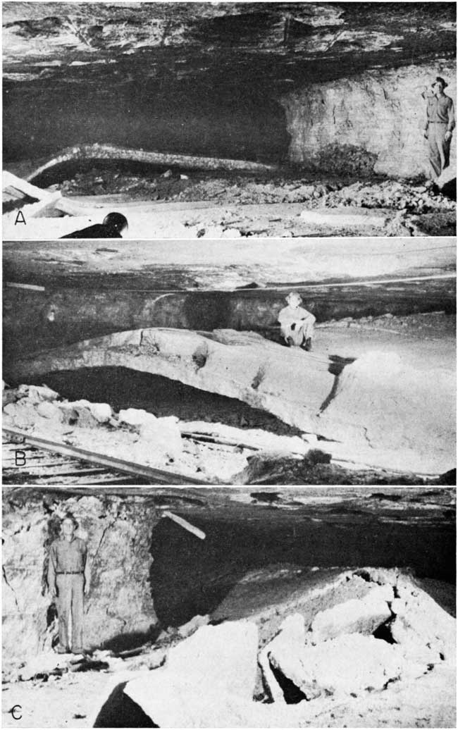
The floor of the Lyons mine is characterized by buckles and by shear and tension fractures. Buckling is reported to begin within one week after the opening of some rooms. These "folds" may form only a small arch on one side of the room (Pl. 1A) or may extend completely across the room, the crest of the fold reaching almost to the roof of the room (Pl. 1B). They generally extend only from crosscut to crosscut in a room or from room to room in a crosscut, but a few have been traced through two crosscuts or rooms, and some folds make a right-angle bend from a room to the adjacent crosscut (Pl. 1B, C). The folds involve only the salt layer above the shale parting and thus are variable in thickness. Many are fractured at the crest and at the junction of arch and floor. (Pl. 2A). In many areas of the mine, well-developed arches have sufficient strength to resist collapse despite constant operation of a shuttle car or railroad over the crest. Some arches have continued to rise even after the installation of track and the operation of the train in the main haulageway.
Plate 1--A. Floor buckles in thin salt layer, showing variations in location and orientation of axes. B. Floor buckles along main haulageway. Room is 48 feet wide and 6.3 feet from original position of floor to roof. At open end of fold 2-foot salt layer has risen 3.2 feet. In rear of room, salt layer has buckled to touch roof. (Camera facing west.) C. Continuation of fold shown in B. In this room only a thin layer of salt was left in floor. (Camera facing south.)
Such structures, although common throughout the Lyons mine, rarely develop in the salt mines at Kanopolis or at Hutchinson, Kansas. A different salt unit is mined at Hutchinson and Kanopolis, and shale layers are not found in the same relationship.
The areas at the intersection of rooms and crosscuts are generally characterized by fractures, which commonly extend diagonally across these areas between corners of pillars. There may be a single fracture, several discontinuous fractures, or a zone of en echelon fractures. Also, fractures approximately normal to the face extend between adjacent pillars and show separation of several inches. Neither fractures nor folds extend below the shale layer in the floor.
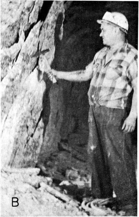
Spalling of pillars occurs throughout the mine (Pl. 2B). It begins near the roof and at the corners of pillars. Severe spalling of the pillars in the room being measured finally forced discontinuance of this study.
Plate 2A--A. Fold at side of room in thin salt layer, showing fracturing at crest and at junctions of limbs with floor.
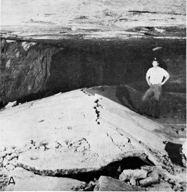
Plate 2B--Spalling of pillar.
It was originally hoped that measurements might be obtained at the base, top, and middle of a pillar in order to show relative amounts of movement. After movement began, however, floor buckles prevented measurement at the base, and spalling, which begins near the roof, prevented accurate measurements there. It also was planned to plot fractures and folds as they developed, but circumstances prevented the accumulation of any significant data. Among those factors that could not be controlled but which influenced deformation were (1) shape, orientation, and size of pillars, crosscuts, and rooms; (2) method of mining (variable rate of removal of salt from rooms and crosscuts); and (3) differences in thickness of the salt layer left above the shale parting in the floor. As a result, measurements were made only between points directly across a room or crosscut approximately half way up the pillars and half way from the corners (Fig. 2). The location of the points was determined by the solidity of the wall. So that early spalling might not affect measurements, wood plugs were set several inches back from the face in holes drilled in the pillars. Pins were driven into the plugs until they were in contact with the salt in the end of the hole. The study was terminated when spalling moved the plugs and pins.
Fig. 2--Sketch of mine plan in study area. Measurements were made with a steel tape, and temperature was recorded, although the mine temperature remains almost constant at 71 to 72° F, and therefore was not a significant factor in measurements.
Five measurements were made on three sides of the pillar and four on the fourth side during a period of 13 1/2 months (Table 1). At the time of the first measurements, movement in the floor had begun. This particular area was selected only because salt was being removed here when the project was begun, but movement so far had been slight.
Table 1--Measurements, in feet, between pillars along lines shown in Figure 2
| A | B | C | D | |
|---|---|---|---|---|
| June 27, 1955 | 38.110 | 48.940 | 50.510 | unmined |
| Nov. 10, 1955 | 37.940 | 48.810 | 50.275 | 49.135 |
| Feb. 9, 1956 | 37.855 | 48.710 | 50.220 | 49.060 |
| June 6, 1956 | 37.780 | 48.645 | 50.130 | 48.990 |
| Aug. 10, 1956 | 37.775 | 48.620 | 50.115 | 48.960 |
Plastic flow of salt within the pillars is indicated by measurable decrease in width of room and crosscut during the period of observation (Fig. 3). In general there has been a decrease in the rate of flowage and, although accurate measurements can no longer be made, it is to be noted that with the decrease in rate of flowage, spalling becomes more common. Thirteen months after the last measurements were taken, continued movement was indicated by further accentuation of earlier formed folds, by opening of new fractures in the floor, and by enlargement of previously developed fractures.
Fig. 3--Curves showing cumulative decrease in measurements along lines A, B, C, and D between pillars.
Flowage continues for a considerable length of time in some areas. For example, at the time of this investigation the arch shown in Plate 2B showed signs of recent movement, although the area had been mined approximately 20 years earlier.
The lateral force exerted by the spreading pillars causes the buckling and fracturing of the floor. In the shale layer in the floor (where it can be seen beneath a buckle) slickensides develop as a result of the sliding of the overlying layer of salt over the shale. The shale bed consists of alternating layers of silty shale and more plastic clay shale, which average about 1/8 inch thick. Movement takes place in the lubricating layers of clay shale. The spalling of pillars indicates that in the later stages the relief of stress by fracture becomes more important than relief by plastic flow. Whereas the amount of flowage has been determined by actual measurement in this area, flowage might be estimated by calculating the reduction in room or crosscut width required to form any floor buckle. The maximum measured amount of movement was observed in a floor buckle in a room 48 feet wide in which a 2-foot salt layer has been raised within 1 foot of the roof at one point (Pl. 1B). This arching would have required a reduction of 1.5 feet in width of the room at floor level. Whereas this represents the maximum shortening observed, the reduction in room and crosscut width in the area studied is less than average, for in adjacent rooms and crosscuts, floor buckles are higher and wider.
The amount of movement and the orientation and kind of structures are determined by: (1) amount of salt left in the floor above the shale parting, (2) thickness and plasticity of the shale, (3) size and orientation of the rooms and crosscuts, and (4) rate of mining and progress of mining around any pillar. Thick layers of salt in the floor usually result in the development of competent arches, which must eventually be blasted down, whereas thin weak layers easily fracture in the arch and fall.
Flowage in the pillars cannot be prevented. Floor buckling might be stopped by channeling through the salt floor and into the shale so that the lateral force exerted by two adjacent spreading pillars cannot be transmitted through the salt floor to cause buckling. If the salt strut is broken, the floor salt layer will yield by sliding along the lubricating shale. It is cheaper, however, to blast when necessary rather than to channel along the wall. That the roof does not buckle where mining is carried to the 9-foot parting but does in many places where mining is extended to the high top suggests that the compressive strength of the 6 1/2 feet of salt in the roof is sufficient to withstand the lateral thrust, whereas the 34 inches of salt between the high top and the next parting is not sufficiently strong to withstand the thrust.
Kansas Geological Survey, Geology
Placed on web June 6, 2007; originally published in 1958.
Comments to webadmin@kgs.ku.edu
The URL for this page is http://www.kgs.ku.edu/Publications/Bulletins/130_4/index.html