![]()
Prev Page--Ground Water || Next Page--Utilization
Ground Water, continued
Ground-water Recharge
Recharge is the addition of water to the ground-water reservoir and may be accomplished in several ways. All ground water within a practical drilling depth in Pawnee and Edwards counties is derived from water that falls as rain or snow either within the area or within adjacent areas. Once the water becomes a part of the ground-water body it moves down the slope of the water table, later to be discharged farther downstream.
The underground reservoir beneath Pawnee and Edwards counties is recharged primarily by local precipitation. Other factors that affect recharge in this area are seepage from streams and depressions and subsurface inflow from adjacent areas. The principal methods of recharge are described in the following paragraphs.
Recharge from precipitation
The mean annual precipitation in Pawnee and Edwards counties is about 23.5 inches, but only a small part of this water reaches the zone of saturation owing to evaporation, transpiration, and direct surface runoff. Water that is not lost by these processes moves downward into the soil zone and a part reaches the zone of saturation.
The amount of water added to or discharged from the groundwater reservoir is reflected in the fluctuations of the water levels in wells. Periodic water-level measurements have been made in three wells (78, 111, and 128) in the Pawnee Valley in Pawnee County since 1940 and measurements in other observation wells (10, 36, 168, 190, 220, and 243) in Pawnee and Edwards counties have been made since 1944. The fluctuations of the water levels in these wells are shown in Figures 7 and 8. Wells 78, 111, and 128 are irrigation wells in the Pawnee Valley west of Larned and wells 36, 168, 220, and 243 are shallow wells in the Arkansas Valley or in the sand-hills area south of the valley. Wells 10 and 190 are deeper wells in the upland areas. The water levels in six of the nine wells were higher at the last measurement than at the first measurement because of the relatively abundant precipitation during the period of record. Periods of heavy precipitation generally are reflected in rises in the water levels in the Pawnee Valley wells (78, 111, and 128). The hydrographs of these wells (Fig. 7) obviously indicate the effects of pumping for irrigation also. The water levels rose abruptly following heavy precipitation during June 1941, and during April, May, July, and August 1944. The water levels in all three wells declined in 1943, which was a period of below-normal precipitation. The relations between the water levels and precipitation as depicted in the hydrographs in Figures 7 and 8 show that the ground-water reservoir is recharged by precipitation.
Recharge from streams
One of the principal sources of recharge of the ground-water reservoir in the Pawnee-Edwards area is the loss of water from the channels of streams. The intermittent streams in this area may carry considerable water during times of floods, during which large volumes of water may percolate through the stream bed and replenish the ground-water reservoir. This type of stream is known as an influent or losing stream (Fig. 6). Recharge from influent streams in Pawnee and Edwards counties probably is confined primarily to the upland areas and to the dune-sand areas south of Arkansas River.
The principal streams in this area (Arkansas and Pawnee Rivers), as well as some of the smaller streams such as parts of Coon, Sawmill, and Ash Creeks, are effluent or gaining streams (Fig. 6). Their base flow is maintained by the discharge of water from the ground-water reservoir. It is possible, however, that the extensive development of irrigation from wells in the Arkansas and Pawnee Valleys could lower the water table to such an extent that Arkansas and Pawnee Rivers would become influent or losing streams. If this were to happen, there would be greatly increased recharge of the ground-water reservoir by loss of stream flow in these rivers.
Recharge from undrained areas
The surface of the area underlain by dune sand is marked by many small undrained depressions (Pl. 4) which catch rain-water and prevent surface runoff. Water that accumulates in these undrained areas generally disappears more quickly than it could be discharged by evaporation and transpiration. Inasmuch as these areas are underlain by dune sand, which is in turn underlain by the relatively permeable beds comprising the Meade formation, it is believed that much of this water moves downward and recharges the ground-water reservoir. After the heavy rains in the summer of 1944, the water table in parts of the dune-sand area was higher than it had been in more than 25 years. The water table was so high in some localities that it flooded some basements for the first time in more than 25 years. This indicates very rapid recharge by precipitation and by seepage from undrained depressions.
Recharge from subsurface inflow
The movement of ground water in Pawnee and Edwards counties, as indicated by the slope of the water table (Pl. 1), is toward the east and northeast; hence, water derived by recharge from precipitation or stream flow in areas to the west and southwest eventually moves into this area and contributes to the supply of ground water.
Ground water in the Dakota formation may be derived locally from overlying or adjacent water-bearing beds, but where the formation is overlain by the relatively impermeable beds comprising the Graneros shale and Greenhorn limestone, the source of water must be in some adjacent area where the formation either crops out or is overlain by permeable beds. For this reason some of the water in the Dakota formation probably is derived from areas outside Pawnee and Edwards counties. The Cheyenne sandstone is over-lain by the relatively impermeable Kiowa shale in all parts of this area; hence, the water it contains is derived from adjacent areas.
Ground-water Discharge
Ground-water discharge is the discharge of water directly from the zone of saturation or from the capillary fringe, and may take place through evaporation and transpiration or as hydraulic discharge through springs, seeps, wells, or infiltration galleries.
Natural discharge
Before wells were drilled in Pawnee and Edwards counties the ground-water reservoir in that area was in a state of approximate equilibrium--that is, the average annual recharge was approximately balanced by the average annual discharge and the water table was moderately stable except for seasonal fluctuations. Water was added to the ground-water reservoir by movement from the west and southwest, by recharge from precipitation and by seepage from streams. Ground water was discharged from the area principally by movement to the east and northeast and by discharge into Pawnee River, Arkansas River, and Rattlesnake Creek. This is well illustrated by the water table contour map (Pl. 1).
Other methods of ground-water discharge in this area are transpiration and evaporation. Water may be taken into the roots of plants directly from the zone of saturation or from the capillary fringe, and be discharged from the plants by the process known as transpiration. The depth from which plants will lift the ground water in an area of given climate varies with different plant species and different types of soil. The limit of lift by ordinary grasses and field crops is not more than a few feet; however, alfalfa and certain types of desert plants have been known to send their roots to depths of 60 feet or more to reach the water table (Meinzer, 1923, p. 82).
Transpiration in the Pawnee-Edwards area probably is relatively large, owing to the shallow depth to the water table in much of the area. The greatest transpiration probably is in Pawnee and Arkansas Valleys, where the water table is very shallow and where most of the trees of the area grow. This is also where most of the alfalfa is grown.
Discharge of ground water by direct evaporation probably is negligible in this area. The only places where the water table would be sufficiently shallow would be along the banks of the streams and in parts of the stream beds.
Discharge from wells
The discharge of water from wells is now one of the principal means of the discharge of water from the ground-water reservoir. In 1943, more than 4,000 acre-feet of water was pumped from irrigation, railroad, and public-supply wells in Pawnee and Edwards counties. During the drought between 1930 and 1940 much more than 4,000 acre-feet per year was discharged by wells, as attested by the fact that only 76 of the 127 irrigation wells listed in Tables 16 and 17 were in operation in 1943. This was caused primarily by improved soil-moisture conditions, but, in part, by the shortage of labor. It is believed that the average pumpage of water for irrigation, railroad, and public-supply use probably exceeded 4,000 acre-feet. Most of the rural residents of the area obtain their supplies of domestic and stock water from wells, but the amount of water used for this purpose is comparatively small. The recovery of ground water from wells is discussed in the next section.
Recovery
Principles of Recovery
The discharge from a well is produced by a pump or some other lifting device or by artesian head. (For a more detailed discussion of principles of recovery see Meinzer, 1923a, pp. 60-68.) When water is standing in a well, there is equilibrium between the head of the water inside the well and the head of the water outside the well. Whenever the head inside a well is reduced, a resultant differential head is established and water moves into the well. The head of the water inside a well may be reduced in two ways: (1) by lowering the water level by a pump or some other lifting device, and (2) by reducing the head at the mouth of a well that discharges by artesian pressure. Whenever water is removed from a well there is a resulting drawdown or lowering of the water level or, in a flowing artesian well, an equivalent reduction in artesian head.
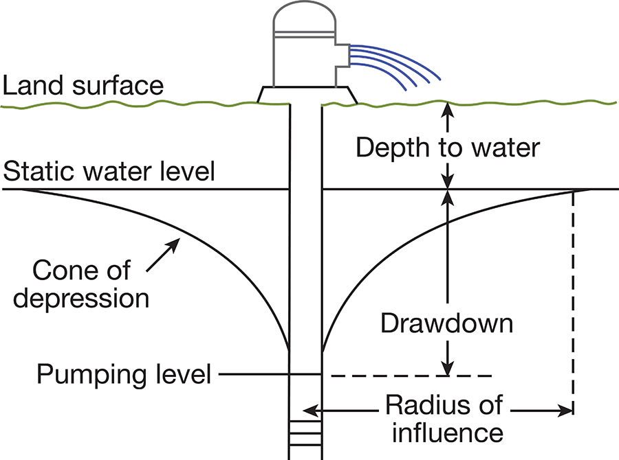
When water is being discharged from a well, the water table is lowered in an area around the well to form a depression somewhat resembling an inverted cone. This depression of the water table is known as the cone of depression, and the distance that the water level is lowered is called the drawdown (Fig. 9). In any well, within certain limits, the greater the rate of pumping the greater will be the drawdown.
Figure 9--Diagrammatic section of well that is being pumped, showing its drawdown, cone of depression, and radius of influence. (From O.E. Meinzer.)
The capacity of a well is the rate at which it will yield water after the water stored in the well has been removed. The capacity depends upon the amount by which the water level can be lowered, the thickness and permeability of the water-bearing bed, and the construction and condition of the well. The capacity of a well generally is expressed in gallons a minute.
The specific capacity of a well is its rate of yield per unit of drawdown, and it is determined by dividing the tested capacity in gallons a minute by the drawdown in feet. If a well yields 1,000 gallons a minute, for example, and has a drawdown of 10 feet when pumped at that rate, then the specific capacity of that well would be 1,000 divided by 10, or 100 gallons a minute per foot of drawdown, or simply 100.
When water is withdrawn from a well, the water level drops rapidly at first and then more slowly until it finally becomes nearly stationary. When the withdrawal of water from a well ceases, the water level rises rapidly at first and then more slowly until eventually it reaches its original position, or approximately its original position.
Dug Wells
Dug wells are excavated with picks, shovels, spades, or by power machinery. They generally are between 2 and 10 feet in diameter and are relatively shallow. Most of the shallow domestic and stock wells in the upland area in northern Pawnee County are dug. Almost all the early irrigation wells were dug to the water table and then drilled the rest of the way, but the newer irrigation wells are drilled. Most of the driven wells in the sand-hills area south of Arkansas River were dug several feet in order to facilitate driving the sand point. In some places the dug part of the well is extended to the water table.
Bored Wells
Bored wells are made by augers or post-hole diggers in unconsolidated sediments. Many wells in the shallow-water areas in the Arkansas Valley were made in this way.
Driven Wells
Most of the domestic and stock wells in the sand-hills area and many of the wells in the Arkansas, Pawnee, and Ash Creek Valleys are driven wells. They generally are made by driving a 1 1/4 to 1 1/2-inch pipe (equipped at the bottom with a screened drive point) down below the water table. Such wells generally can be put down only where the water-bearing material is sufficiently permeable to permit water to flow freely into the pipe, where the material is unconsolidated enough to permit a pipe to be driven, and where the depth to water level is not more than about 20 feet below land surface. Where the material near the surface is too consolidated to permit a pipe to be driven, the well generally is dug to a less consolidated zone and where the depth to water exceeds 20 feet the well generally is dug part way so that the distance from the pump cylinder (at the bottom of the dug part of the well) to the water table is less than 20 feet. Driven wells in the areas of very shallow water in the Arkansas Valley generally are equipped with a pitcher pump, whereas in areas where the water table is deeper they generally are equipped with a cylinder pump, the cylinder being placed at the bottom of the dug part of the well.
Drilled Wells
A drilled well is one that is excavated by means of a percussion or rotary drill. In Pawnee and Edwards counties the drilled domestic and stock wells generally are 4 to 6 inches in diameter and are cased with galvanized-iron or wrought-iron casing. The irrigation and public-supply wells generally are between 8 and 24 inches in diameter. Most of the irrigation and public-supply wells in the valley and sand-hills areas and the deep domestic and stock wells in the upland areas in northern and western Pawnee County and in northwestern Edwards County are drilled wells.
Drilled wells in consolidated deposits
Almost all the drilled wells in Pawnee and Edwards counties that are in or near the areas of Cretaceous outcrops are drilled into consolidated deposits. Most of these wells penetrate shale and limestone of the Carlile shale and/or the Greenhorn limestone and end in sandstone in the Dakota formation. They generally are cased to the bottom but a few are cased through the unconsolidated superficial material and a few feet into bedrock. Water may enter the well along the entire uncased part of the hole, but the materials above the Dakota formation in these areas generally are nearly barren of water. In the Pawnee Valley a few wells obtain water from the Dakota formation, the water of poorer quality in the alluvium being cased off.
Drilled wells in unconsolidated materials
Unconsolidated materials of Quaternary age supply most of the water to wells in Pawnee and Edwards counties. Wells in these deposits generally are cased nearly to the bottom of the hole with galvanized-iron or wrought-iron casing. Water enters most of the wells through the end of the casing but the irrigation, railroad, and public-supply wells generally have perforated casing to provide better intake facilities. The size of the perforations is an important factor in the construction of a well and the capacity or even the life of the well may be determined by it. If the perforations are too large the fine material may filter through and fill the well, and if the perforations are too small they may become clogged so that water is prevented from entering the well freely.
Some wells in unconsolidated sediments are equipped with well screens or strainers. It is common practice to select a slot size that will pass 30 to 60 percent of the water-bearing material, depending upon the texture and degree of assortment. Retention of the coarser particles around the screen forms a natural gravel packing that greatly increases the effective diameter of the well, hence increasing its capacity.
Gravel-wall wells generally are effective for obtaining large supplies of water from relatively fine-grained unconsolidated deposits, and are widely used for irrigation. In constructing a well of this type, a hole of large diameter, 30 to 60 inches, is first drilled by the rotary method or by means of an orange-peel bucket and is temporarily cased with unperforated pipe. A well screen or perforated casing of smaller diameter than the hole is then lowered into place and centered in the large pipe opposite the water-bearing beds. Unperforated casing extends from the screen to the surface. The annular space between the inner and outer casings is then filled with sorted gravel, preferably of a grain size just a little larger than the openings in the screen or perforated casing, and also slightly larger than that of the water-bearing material. In most wells of this type a medium- or coarse-grained gravel is used, but in very fine-grained deposits a fine-grained gravel or a coarse-grained sand must be used. The outer casing is then withdrawn part way to uncover the screen and to allow the gravel packing to come in contact with the water-bearing material. In deciding whether or not to use gravel-wall construction it is important to know the character of the water-bearing material. If the material is coarse and well sorted, it generally is unnecessary to construct a gravel-wall well.
According to McCall and Davison (1939, p. 29) the drawdown in a well can be kept at a minimum in several ways:
First, the well should be put down through all valuable water-bearing material. Secondly, the casing should be properly perforated so as to admit water to the well as rapidly as the surrounding gravel will yield the water. Third, the well should be completely developed so that the water will flow freely into the well. . . . Increasing the depth of a well will have a greater effect on reducing the drawdown than will increasing the diameter, so long as additional water-bearing formations are encountered.
A report (Davison, 1939) containing descriptions of different types of pumping plants, the conditions for which each is best suited, construction methods, and a discussion of costs of construction is available from the Division of Water Resources, Kansas State Board of Agriculture, Topeka, Kansas, and the reader is referred to this publication for additional details of well construction.
Methods of Lift and Types of Pumps
Most of the domestic and stock wells in Pawnee and Edwards counties are equipped with lift or force pumps. The cylinders or working barrels in lift pumps and in force pumps are similar and are located below the land surface, either above or below the water table; a lift pump generally discharges water only at the pump head, whereas a force pump can force water above this point-such as to an elevated tank. Pitcher pumps are used on many of the driven wells in the Arkansas Valley and on a few of the driven wells elsewhere in the area. Domestic and stock wells in the Pawnee-Edwards area generally are operated by windmills but the pitcher pumps and a few of the lift pumps are hand operated.
The discharge pipes in driven wells generally are 1 1/4 to 1 1/2 inches in diameter and in drilled wells they generally are 1 1/4 to 3 inches in diameter. The discharge pipes in the larger irrigation and public supply wells are 4 to 10 inches in diameter.
Irrigation and public-supply wells in this area are equipped with large centrifugal and turbine pumps. The centrifugal pumps are used mainly in the old irrigation plants consisting of one or more dug and drilled wells connected to one pump. The turbine pumps are used primarily in the newer deep irrigation and public-supply wells. Both types of pumps generally are equipped with large engines using gasoline or electricity for power.
Prev Page--Ground Water || Next Page--Utilization
Kansas Geological Survey, Pawnee and Edwards Geology and Groundwater
Comments to webadmin@kgs.ku.edu
Web version June 2004. Original publication date March 1949.
URL=http://www.kgs.ku.edu/General/Geology/Pawnee/06_gw2.html