![]()
Prev Page--Recharge || Next Page--Utilization
Ground Water, continued
Ground-water Discharge
Water is discharged from the underground reservoir that lies beneath Finney and Gray counties by transpiration and evaporation, seepage into streams, springs, underflow that leaves the area, and by wells. Other things being equal, the stage of the water table and the season of the year are the principal factors controlling the rate at which ground water is discharged. Transpiration and evaporation of water from the zone of saturation are confined exclusively to those areas where the water table is very shallow, such as the Arkansas valley. The greatest amount of water withdrawn from the underground reservoir by wells is in the vicinity of Garden City where the greatest amount of irrigation is carried on. Seepage of ground water into streams occurs only along Arkansas and Pawnee rivers, and discharge by springs is confined to the area occupied by Pawnee River and its tributaries. In areas where the water table lies at great depth there is no natural discharge except for the water that is moving laterally out of the area beneath the surface. A few domestic and stock wells pump water from the ground-water reservoir in such areas, but the amount of water withdrawn in this way is relatively small.
Water-table contours on the map (pl. 1) indicate that water is slowly moving out of the County beneath the surface toward the east. The amount of water leaving Finney and Gray counties in this way is approximately equal to the amount of water that enters the area from the west plus additions to, or subtractions from, the ground-water reservoir that occur within the two counties.
Before the development of wells in Finney and Gray counties, the annual natural discharge of ground water probably was approximately equal to the annual recharge. The artificial discharge of water by wells has interrupted this balance between natural discharge and recharge. Through a period of many years, however, there will be a readjustment of natural discharge to take into account the artificial discharge of water by wells, and after this readjustment takes place there will again be an approximate balance between annual discharge and annual recharge. Such a readjustment of discharge, however, may result in a gradual regional lowering of the water table: This regional lowering of the water table probably will be very slight, for the amount of water in underground storage is very large.
Transpiration and evaporation
Water may be taken into the roots of plants directly from the zone of saturation or from the capillary fringe, and discharged from the plants by the process known as transpiration (Meinzer, 1923a, p. 48). The depth from which plants will lift ground water varies with different plant species and different types of soil. The limit of lift by ordinary grasses and field crops is not more than a few feet, but some types of desert plants have been known to sand their roots 60 feet or more below the surface to reach the water table (Meinzer, 1923, p. 82). Most ordinary grasses and field crops obtain water only from the upper few feet of soil. Plants such as corn, wheat, and barley probably obtain water from depths not exceeding 7 feet. Alfalfa is unusual in that it will send its roots to a depth of 20 or 30 feet in order to obtain water.
Discharge of ground water by transpiration from the zone of saturation or from the capillary fringe in Finney and Gray counties is limited to the stream valleys and to the deeper depressions in the Finney basin where the water table is within 10 or 15 feet of the land surface. Water-loving trees, particularly cottonwoods, are found along most of the stream valleys and around some of the depressions in the Finney basin. Where cottonwood trees occur, the depth to water generally does not exceed 20 feet (Meinzer, 1927, p. 58). In the Arkansas valley the discharge of ground water from the zone of saturation by transpiration is limited to areas adjacent to Arkansas River where the water table is comparatively close to the surface.
The amount of water discharged annually by plant transpiration is probably negligible in those areas where the water table lies more than 20 feet below the surface; however, in the Arkansas valley and parts of the Finney basin, where the water table is shallow, the amount of ground water discharged by plants is large. Wenzel (Lugn and Wenzel, 1938, p. 151) estimated that in the Platte River valley between Chapman and Gothenburg, Nebraska, an average of 12 inches of supplemental water is used annually by plants whose roots extend to the zone of saturation, or about 12 times the quantity of water that was at that time pumped annually from wells.
In areas where the water table is shallow, some ground water from the zone of saturation evaporates directly into the atmosphere. Water discharged in this manner is drawn from the zone of saturation and is evaporated from the capillary fringe. If the capillary fringe does not extend to within a few feet of the land surface, no water is lost from the zone of saturation by evaporation. The depth to ground water over most of Finney and Gray counties is great enough so that in most areas no water is lost by evaporation. The greatest loss of ground water by evaporation occurs in the bed of Arkansas River when it is dry. Some water probably is discharged by evaporation from the underground reservoir in those depressions in the Finney basin where the water table is very shallow. The rate of evaporation of ground water is determined principally by the type of soil, the depth to the water table, and weather conditions, all of which have great variations in Finney and Gray counties.
A stream that stands lower than the water table may receive water from the zone of saturation, and is known as an effluent stream (fig. 14). Arkansas River is the only stream in this area that gains water from the main ground-water reservoir. Part of Pawnee River receives effluent seepage, but the water comes from the alluvium in the Pawnee valley which is isolated from the main underground reservoir by an outcrop area of a relatively impermeable Cretaceous shale.
Except at flood stages, Arkansas River is a gaining stream throughout its course in Gray County and eastern Finney County. During the 18-year period from October 1, 1922, to September 30, 1940, (table 7) the river gained in flow between Garden City and Lamed each year except four (1922-1923, 1923-1924, 1924-1925, 1935-1936). Part of this gain in flow was supplied by runoff from precipitation, and a part came from the ground-water reservoir as effluent seepage.
There is a delicate balance between the level of Arkansas River and the adjacent water table throughout most of Finney County. Fluctuations of the water table or changes in discharge of the river may cause the Arkansas to become either a losing or gaining stream. During certain periods the bed of Arkansas River in Finney County is dry and lies above the water table (p. 75). During these periods a large part of any water flowing in the river after heavy rains sinks into the alluvium and joins the underground reservoir. At other times the Arkansas in Finney County is a gaining stream and receives water from the underground reservoir.
Discharge from springs
Some water is discharged through springs along Pawnee River and its tributaries as described on pages 87, 88, but springs are not known to occur in any other area in Finney and Gray counties. All of the springs are along the escarpment of the High Plains and appear at or near the contact between the water-bearing sands and gravels of the Ogallala formation and the underlying Cretaceous shales and limestones. Although all of the springs occur in valleys none of them has sufficient flow to give rise to streams. It is probable that there is a large amount of seepage along the escarpment that is not noticeable, the water probably being lost by evaporation and transpiration faster than it seeps out of the ground. The water-table contours (pl. 1) show that much more water is being discharged along the escarpment than is indicated by the few small springs that were observed.
Discharge from wells
In 1939, more than 38,000 acre-feet of water was pumped from irrigation, industrial, and public supply wells in the two counties. Additional water is withdrawn by domestic and stock wells, but the total amount of water pumped from these wells is comparatively small.
When a well is pumped, the water table in the vicinity of the well declines and takes a form similar to an inverted cone, called the cone of depression. When pumping stops, the cone of depression is gradually filled with water from adjacent areas. As a result, the regional water table declines slightly until the surface of the water table again becomes practically smooth. After the end of the pumping season in Finney and Gray counties, the regional water table tends gradually to assume a form similar to the form it had before pumping began. The regional water level in the reservoir, however, generally is lower than it would have been had there been no pumping.
Pumping a well lowers the water level not only in the pumped well but also in all wells that are within the area of influence (area affected by the cone of depression). The influence of a pumping well on the water level of a nearby well is shown by the hydrograph of well 138 in figure 17. Well 138 is about 300 yards from a large irrigation well (139). The hydrograph is based upon monthly Water-level measurements; therefore, it does not show the changes in water level that occur between measurements.
Figure 17--Hydrograph of well 138 showing changes in water level caused by a near-by pumping well.
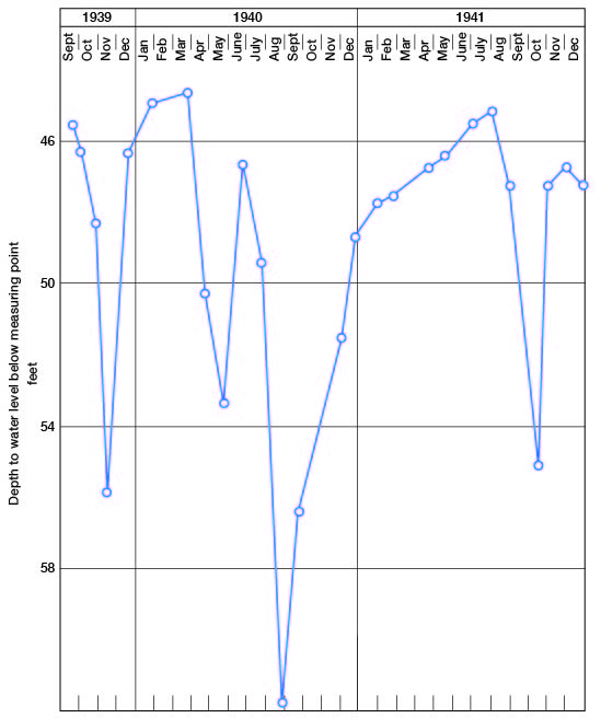
The time and length of the pumping season in this area vary from Year to year, depending mainly on the amount and distribution of precipitation. The main pumping season usually extends from May or June through September or October, although some wells are pumped at other times during the year. The low water levels in wells in the pumping area usually are reached at or near the end of the pumping season. After pumping has stopped, there is a period of recovery during which time the water table gradually rises.
After a season of heavy pumping, the water table is usually lower than it was at the beginning of the pumping season. This lowering of the water table during the pumping season is not permanent, for the water table generally rises as a result of the recharge caused by precipitation that falls during non-pumping seasons. If heavy pumping and a deficiency in annual precipitation continue year after year, there will be a cumulative decline in the regional water table (pp. 71, 72, fig. 13). If the precipitation is great enough during the growing season to supply the necessary moisture to the crops, there will be little or no heavy pumping and the water table will not decline appreciably; if the precipitation is greater than the needs of the crops, the water table may actually rise.
Recovery of Ground Water
Springs
Eleven springs and seepage areas were observed along Pawnee River and its tributaries (pl. 2). Small supplies of water are recovered from most of these springs for stock use.
All of the springs observed in this area are gravity springs; that is, the water does not issue under artesian pressure but discharges by gravity along an outcrop of the water table. According to Meinzer (1923a, p. 51), the water of a gravity spring percolates from permeable material or flows from large openings in a rock formation, under the action of gravity, as a surface stream flows down its channel. Gravity springs may be further classified as depression springs, where waters flow to the surface from permeable material simply because the surface extends down to the water table; as contact springs, whose waters flow to the surface from permeable material over the outcrop of less permeable or impermeable material that retards or prevents the downward percolation of the ground water and thus deflects it to the surface; and as fracture springs, whose waters flow to the surface from fractures in the rocks (Meinzer, 1923a, pp. 50-52). These different types of springs may grade into one another. The springs observed in Finney County are either contact springs or fracture springs. The contact springs (nos. 44, 45, 51, and 52 on pl. 2) all occur on the valley slopes or bottoms of tributaries south of Pawnee River. These springs issue from permeable beds of sand and gravel at the base of the Ogallala formation near its contact with the underlying Carlile shale. There are other seepage areas along tributaries of Pawnee River which are not shown as springs on the map (pl. 2). There generally is not visible discharge of water at such seeps, but the vegetation near the contact is more luxuriant, indicating that the plants are using the ground water as fast as it is being discharged.
The fracture springs all occur along the western and northwestern edges of the Cretaceous outcrop area (nos. 15, 16, 17, 18, 63, 66, and 103 on pl. 2). These springs issue from fractures in the Fort Hays limestone member of the Niobrara formation. The openings in most of the fracture springs are more or less sheet-like. The Fort Hays limestone member of the Niobrara dips beneath the water-bearing beds of the Ogallala formation. Part of the ground water that percolates eastward through the Ogallala formation enters fractures and bedding planes in the underlying limestone. Springs occur where these water-bearing fractures or bedding planes have been exposed at the surface by erosion.
The estimated discharges of the springs ranged from less than 1 gallon a minute to 2 or 3 gallons a minute.
Wells
Principles of Recovery from Wells
The following discussion on the principles of recovery of ground water has been adapted in part from Lohman (1938, pp. 54-56).
When water is withdrawn from a well there is a difference in head between the water inside the well and the water in the surrounding material at some distance from the well. The water table in the vicinity of a well that is discharging water has a depression resembling in form an inverted cone, the apex of which is at the well. This depression of the water table is known as the cone of influence or cone of depression, and the surface area affected by it is known as the area of influence. In any given well the greater the pumping rate the greater will be the drawdown (depression of the water level, commonly expressed in feet) and the greater will be the diameter of the cone of influence and of the area of influence.
The specific capacity of a well is its rate of yield per unit of drawdown and is usually stated in gallons a minute per foot of drawdown. For example, well 131 has a measured yield of 1,100 gallons a minute with a drawdown of 18.5 feet. Its specific capacity, therefore, is 59.5 gallons a minute per foot of drawdown.
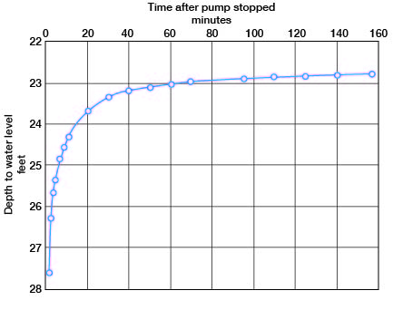
When a well is pumped, the water level drops rapidly at first and then more slowly, but it may continue to drop for several hours or days. In testing the specific capacity of a well, therefore, it is important to continue pumping until the water level remains approximately stationary. When the pump is stopped the water level rises rapidly at first, then more slowly, and may continue to rise long after pumping has ceased. The recovery curve of well 454 is shown in figure 18.
Figure 18--Recovery curve of well 454, in the Arkansas valley in central Gray County. Well was pumped at a rate of 592 galons a minute prior to recovery period.
The character and thickness of the water-bearing materials have a definite bearing on the yield and drawdown of a well, and in turn on the specific capacity of a well. Drawdown increases the height that the water must be lifted in pumping a well, thus increasing the cost of pumping (p. 93). If the water-bearing material is coarse and of a fairly uniform size, it will readily yield large quantities of water to a well with a relatively small drawdown; if the water-bearing material is fine and poorly sorted, it will offer more resistance to the flow of water into a well, thereby decreasing the yield and increasing the drawdown. Other things being equal, the drawdown of a well varies inversely with the permeability of the water-bearing material.
The specific capacity of wells, particularly in unconsolidated materials, generally can be greatly increased by the employment of special methods of well construction, as described on pages 93-96.
Methods of Lift
Most of the farm wells in Finney and Gray counties from which domestic and stock supplies are obtained are equipped with lift or force pumps, which are operated by windmills or by hand. A few are operated by small engines or electric motors. Some of the farms have small pneumatic pressure systems in which the water is forced against air pressure into an airtight tank from which it flows under pressure to any part of the home or farm buildings.
Most of the irrigation wells in the Arkansas valley are equipped with centrifugal pumps of the horizontal type, although there are a few wells equipped with vertical centrifugal or turbine pumps. Centrifugal pumps can be used only where the depth to water level below the pump plus the drawdown does not exceed the working suction limit. All of the upland irrigation wells and a few of the deeper irrigation wells in the Arkansas valley are equipped with turbine pumps. Most of the centrifugal or turbine pumps used for irrigation are powered by electric motors, but a few are powered by stationary gasoline engines, natural-gas engines, Diesel engines, or tractors. A few of the pumps are operated by engines using butane for fuel.
All industrial wells in the area, including the railroad wells, are equipped either with horizontal centrifugal or turbine pumps driven by electric motors. Most of the municipal wells in the area are equipped with turbine pumps driven by electric motors. The pump on one municipal well (539) at Copeland, however, is driven by a natural-gas engine. One well (119) in Finney County flows at the surface (p. 55) and, therefore, does not have to be pumped.
Dug Wells
Dug wells are wells that have been excavated by hand, generally with pick and shovel. In places where the walls will not stand alone, dug wells are cribbed with casings of wood, rock, concrete, or metal. As a rule, dug wells are more subject to surface contamination than are properly constructed drilled wells. Moreover, as dug wells generally extend only a few feet below the water table, they are more likely to go dry during periods of drought than the deeper drilled wells. Most dug wells tap rather poor water-bearing material, but because of their large diameter they have a large infiltration area and large storage capacity.
Of a total of about 390 wells visited in Finney County, 10 were dug wells. Of the 10 dug wells, 7 supply water for domestic and stock use and 3 were not in use. Of the 143 wells visited in Gray County, only one (525) was a dug well and two (wells 402 and 492) were dug wells that had been deepened by drilling. Well 525 is a shallow domestic and stock well dug in alluvium. Wells 402 and 492 are irrigation wells that were dug down to about the water level, below which a smaller diameter hole was drilled and cased into water-bearing sand and gravel.
Bored Wells
Bored wells are put down by means of an auger turned by hand or gasoline power. They are generally shallow wells of small diameter put down in soft unconsolidated materials. Of about 530 wells visited in Finney and Gray counties, 25 are known to be bored wells. Most of these wells are less than 25 feet in depth, although a few are more than 50 feet in depth. Most of them are 6 inches or smaller in diameter. About 20 of the 25 bored wells are in stream valleys or in the Finney basin where water is found in soft unconsolidated material at shallow depth. All of the bored wells are used to furnish small water supplies for domestic and stock use.
Driven Wells
In many of the stream valleys containing alluvium, particularly the Arkansas valley, and in the Finney basin a few driven wells are used for domestic and stock supplies. Driven wells are adapted only to soft granular formations, which are easily penetrated by the drive point in places where the water table is within 10 or 15 feet of the surface. They generally consist of a 1 1/4- or 1 1/2-inch pipe with a screened drive point at the bottom. Most of them are equipped with hand-operated pitcher pumps attached directly to the pipe. Some of them, however, have a cylinder in a pit just above the water table, and are equipped with lift or force pumps.
Drilled Wells
There are two common methods of drilling wells, by percussion and by the hydraulic-rotary method. A portable cable-tool drill rig mounted on a truck is generally used in the percussion method. This method of drilling consists of raising and lowering a heavy bit on the end of a steel cable, which is threaded over a sheave at the top of a tower or mast. The crushed material in the bottom of the hole is mixed with water and removed by means of a bailer. In the hydraulic-rotary method, the hole is made by the rapid rotation of a bit on the bottom of a string of drill pipe. In this method removal of the cuttings is accomplished by circulating mud-laden fluid down through the drill pipe and up through the annular space between the drill pipe and the hole. The cuttings are brought to the surface as fragments suspended in the mud. The mud also serves to plaster the walls of the hole, thereby preventing caving until the casing is installed.
Most of the stock and domestic water supplies and all irrigation, municipal, and industrial water supplies in Finney and Gray counties are obtained from drilled wells.
Construction of wells in consolidated deposits--A few drilled wells in the "panhandle" of Finney County and in southeastern Gray County obtain water from consolidated rocks--shale, limestone, or sandstone. Most of these are open-end wells; that is, the hole is cased through the overlying unconsolidated material and a few feet into the consolidated rocks, but the lower part of the hole is not cased. Holes drilled into consolidated rocks, particularly in shale or limestone, will as a rule stand open without casing. In drilling in sandstone, however, it may be necessary to case the hole from top to bottom to prevent caving. The yields of drilled wells in the various consolidated rock formations are discussed on pages 143, 145, 146, 153, 156, and 159.
Construction of wells in unconsolidated deposits--More than 95 percent of the wells visited in Finney and Gray counties obtain water from unconsolidated deposits. It is necessary to case these wells the full depth of the hole in order to prevent caving of the walls. In some wells the casing has been perforated in the lower part; in other wells the casing is open only at the bottom. Perforating the casing greatly increases the area of intake, and thus the specific capacity of the well is increased and the entrance velocity of the water is reduced. Well screens are used in some wells to prevent fine sand from entering the well and to increase the intake area.
The dominant type of domestic and livestock well in this area is a cased drilled well containing a separate pipe and cylinder for conducting the water to the surface. Tubular wells predominate in some parts of the uplands in the northern half of Gray County, however. A tubular well is a drilled well with no separate pump pipe. The pipe that conducts the water to the surface acts also as the casing. Wells of this type generally are 2 to 4 inches in diameter and consist of a galvanized-iron pipe at the bottom of which is attached a screened point and a brass-lined cylinder. The submerged cylinder is connected with a pump at the surface by rods within the pipe. The principal advantage of tubular wells is the lower cost. The chief disadvantage of this type of well is the difficulty in pulling the pipe to repair the cylinder. There is also danger of the hole caving while the repairs are being made.
Many of the larger municipal, industrial, and irrigation wells in this area are gravel-packed wells. In constructing this type of well, a hole of large diameter (48 to 60 inches) is first drilled and temporarily cased. A well screen or perforated casing of a smaller diameter than the hole (12 to 25 inches) is then lowered into place and centered opposite the water-bearing beds. Blank casing extends from the screen to the surface. The annular space between the inner and outer casings then is filled with carefully sorted gravel--preferably of a grain size just slightly larger than the openings in the screen or perforated casing, and also just slightly larger than that of the water-bearing material. The outer casing is then withdrawn part way in order to uncover the screen and to allow the water to flow through the gravel packing from the water-bearing material.
The logs of some of the test holes drilled during the investigation reveal that in places the water-bearing materials are sufficiently coarse and well sorted so that gravel-packed wells are not required in order to obtain large yields. In such places less expensive wells employing well screens or slotted casings, but without gravel packing, may be used satisfactorily. In places where the water-bearing materials are fine-grained, however, the gravel-packed wells have several advantages that offset the greater initial cost. The envelope of selected gravel that surrounds the screen greatly increases the effective diameter of the well, and hence decreases the velocity of the water entering the well. This reduction in velocity prevents the movement of fine sand into the well and increases the production of sand-free water. Owing to the increased effective area offered by this type of construction, the entrance friction of the water is reduced and hence the drawdown may be reduced appreciably. As stated above, a reduction in drawdown, at a given yield, increases the specific capacity and reduces the cost of pumping.
Several methods have been used in constructing irrigation wells in Finney and Gray counties. Some wells have been put down by the owners, but most of them were put down by professional well drillers. Generally one or more test holes of small diameter are put down before drilling is started on the final well. Information gained from test drilling is important as a guide in determining the depth and type of irrigation well to be constructed at a particular site.
The most common drilling methods used in this area are the sand bucket method, orange-peel bucket method, and the hydraulic-rotary method. The method used depends on the depth of the well and the character of the material through which the well is drilled, and may be governed also by the type of equipment that is available. The sand bucket method generally is best suited for areas where the water level lies at shallow depths and, therefore, is widely used in the Arkansas valley. This method is limited to use in sand or gravel and is not satisfactory where a large amount of clay or hard material is encountered. The most common type of sand bucket consists of a cylinder, with a check valve at the bottom, enclosing a plunger attached at the top to a rope or cable. Portable rigs, generally mounted on trucks, or a tripod and pulley are used to operate the bucket.
Another method employed in drilling irrigation wells of large diameter is the orange-peel bucket method. When either of the above methods are used, an open pit generally is dug by hand or bored with an auger down to the water table or to loose sand, whichever is encountered first. Sectional casing is then installed and from then on the well is put down by removing the material from the hole by using the sand bucket or orange-peel bucket. The casing is forced down as the material is removed from the hole.
A third method of putting down irrigation wells is the hydraulic-rotary method which is described on pages 91, 92. This is the quickest and generally the most practical method for putting down deep wells. Most of the upland wells and the deep valley wells in this area have been drilled by this method. In drilling a well by the hydraulic-rotary method no casing is used until the drilling has been completed, as the drilling mud prevents the walls of the hole from caving. A casing slightly smaller than the hole is placed in the well after the well has been drilled to the desired depth. If it is to be a gravel-packed well, the space between the hole and the casing is filled with gravel of the proper size.
Casings used for most irrigation wells in this area range from 16 to 24 inches in diameter and are of various types. The most common type of casing used for irrigation wells is made of perforated galvanized iron. Boiler steel and used oil-well casing are sometimes used, particularly in deep wells. Many irrigation wells are cased with concrete rings manufactured locally. The casings are assembled a few rings at a time as the well is being drilled. Vertical iron rods or cables that pass through holes in the rings act as guides in lowering the rings into the well. In one type of concrete casing the water enters the well through spaces between the rings; in another type each ring has vertical slots through which the water enters the well. A few irrigation wells have been cased with casing made from old oil drums. Casing perforated by a manufacturer according to specifications, however, is most satisfactory.
The most common type of irrigation pumping plant in the Arkansas valley consists of two or more wells connected to one centrifugal pump by a common suction pipe laid in the ground just above the water table. These are commonly called "battery wells" (pl. 6), and are constructed only where the depth to water level is comparatively small--generally less than 20 feet. In most installations the wells are put down about 40 feet apart in a straight line at right angles to the direction of the movement of the ground water. Pits are dug to the water table and later walled up with cement blocks or concrete. A perforated casing, generally of galvanized iron, is sunk in each well through the water-bearing beds using a sand bucket. Pump pipes are placed in each well and connected by a pipe laid in a trench or tunnel between the wells. A horizontal centrifugal pump is set in a pit just above the water table in the middle of the line of wells. It is important that the wells in a battery be spaced far enough apart so that there will be as little interference between wells as possible (p. 111, table 16).
The number of wells in a battery commonly ranges from 2 to 16. Table 8 shows the number of wells in battery-well plants in this area and the number of each recorded during the investigation.
Table 8--Number of battery-well plants in the Arkansas valley in Finney and Gray counties classified according to the number of wells in a battery.
| Number of wells in battery |
Number of plants | Number of wells in battery |
Number of plants | |
|---|---|---|---|---|
| 2 | 38 | 10 | 3 | |
| 3 | 28 | 11 | 1 | |
| 4 | 15 | 12 | 2 | |
| 5 | 12 | 13 | 1 | |
| 6 | 14 | 14 | 1 | |
| 7 | 1 | 16 | 1 | |
| 8 | 7 |
In 1940, there were 119 single-well irrigation plants in Finney and Gray counties. About 60 of the 119 wells are deep upland wells, 4 are deep valley wells, and 57 are shallow wells in the valley. The four deep irrigation wells (160, 198, 276, 450) in the valley are so constructed that they draw water not only from the shallow alluvium but also from sands and gravels in the Pleistocene beds and in the Ogallala formation. The wells are 95, 140, 170, and 274 feet in depth. Single-well plants of this type are capable of yielding 1,000 gallons a minute or more.
Assuming that a well of the best possible construction is employed, then the maximum amount of water that can be withdrawn from the well is fixed by nature and nothing can be done to make the well yield more than the water-bearing material will provide. The problem for the driller is to construct each individual well in such a manner as to obtain the greatest yield with the smallest amount of drawdown that is possible under the existing conditions.
According to McCall and Davison (1939, p. 29) drawdown can be kept to a minimum in several ways.
"First, the well should be put down through all valuable water-bearing material. Secondly, the casing used should be properly perforated so as to admit water to the well as rapidly as the surrounding gravel will yield the water. Third, the well should be completely developed so that the water will flow freely into the well ... Increasing the depth of a well will have a greater effect on reducing the drawdown than will increasing the diameter, so long as additional water-bearing formations are encountered."
A report (Davison, 1939) containing a description of different types of pumping plants, the conditions for which each is best suited, construction methods, and a discussion of construction costs is available from the Kansas State Board of Agriculture, Topeka, Kan., and the reader is referred to this publication for details of well construction. The reader is also referred to a report by Rohwer (1940) in which he describes the various methods of irrigation-well construction. This report may be obtained from the Superintendent of Documents, Washington, D.C.
Prev Page--Recharge || Next Page--Utilization
Kansas Geological Survey, Geology
Web version April 2002. Original publication date Dec. 1944.
Comments to webadmin@kgs.ku.edu
The URL for this page is http://www.kgs.ku.edu/General/Geology/Finney/06_gw6.html