|
|
|
|
Jan. 28, 2004, Site Visit--End of First Acquisition |
|
|
|||
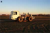
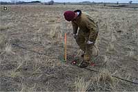
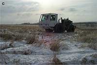
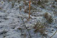
Adjustments made to the data acquisition procedures insured changes from the dry, warm conditions present at the start of this survey to the snow/ice covered ground and frigid temperatures endured during the latter days of this first 3-D monitoring survey (Figure 1) had little or no distinguishable effects on the recorded data. For example, the vibrator pad was continuously cleared of snow to maintain optimum coupling. KGS experience acquiring data in arctic regions was extremely beneficial in and critical to maintaining the highest possible data quality even when temperatures dropped below -6° F with a stout breeze and light snow cover on the ground.
| Click on any photo to view a larger version | |
|---|---|
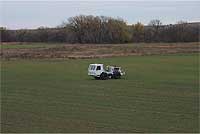
| Figure 1 (a and b) Conditions during week of January 19. | |
 |
 |
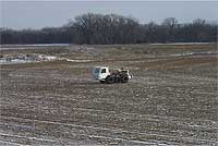
| Figure 1 (c and d) Conditions during week of January 26. | |
 |
 |
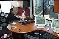
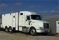
To insure acquisition of the highest quality data set, all shot records are reviewed and preliminary processing completed on each vibrator sweep on-site (Figure 2). Over 4000 uncorrelated, 12-second vibrator sweeps are recorded as part of each 3-D survey. Uncorrelated shot records are downloaded via Ethernet to on-site computers located in the mobile processing center (MPC--Figure 2). Then the data are corrected for spectral attenuation, correlated, spectral balanced, edited, filtered, and vertically stacked. Data from shot stations with excessive noise or noise inconsistent with that observed on records from other shot stations in proximity are re-recorded to improve signal quality.
| Click on either photo to view a larger version | |
|---|---|
| Figure 2 View from front of truck toward computer workstations (left), processing box (right) is climate controlled and mounted on truck frame with ride-controlled air suspension. A 12-kilowatt generator provides both 240-volt and 120-volt power. |
|
 |
 |
Qualitative analysis is used to determine if shot records possess unacceptable noise levels. Determining stations that need to be re-occupied is generally a straightforward process. High frequency random noise, elevated by as much as 6 dB over adjacent stations, can be easily identified. In general, noise level increases of as little as 3 dB are sufficient to justify re-acquiring all five sweeps at that location (Figure 3).
| Click on any figure to view a larger version | |
|---|---|
| Figure 3 Average, relatively low noise, correlated shot gather (left) with adjacent shot station (right) possessing elevated noise levels. |
|
 |
 |
 |
 |
 |
 |
Visually dramatic increases in noise between two source stations located within 20 m of each other are usually related to earth coupling of the vibrator or gusty winds. Either way re-acquiring the data can only be accomplished real-time while all the equipment and crew are on-site and the CO2 position is relatively constant (at least with respect to the size of the seismic wavelet). Considering the need that time lapse analysis has for high S/N data, this step is imperative for obtaining the highest resolution, most representative series of snap shots of the CO2 movement through this shallow (950 m), thin (5 m) reservoir.
Changes in reflections from within the interval of interest can be observed on raw shot records (Figure 4). It is not clear that these changes are related to the presence of CO2. It will require significantly more processing to determine this. However, it is encouraging to see reflection characteristics changing within thin zones near the depth interval receiving CO2, while reflection characteristics from rock layers shallower and deeper remain consistent between these two data sets separated in time by over six weeks. It would be premature to suggest these changes in reflection character are direct indicators of changes to reservoir characteristics due uniquely to the presence of CO2 during this late January survey where it was not during the mid-November baseline survey.
| Click on either photo to view a larger version |
|---|
| Figure 4 Before CO2 injection (top) compared to after CO2 injection (bottom). Reflections from the L-KC should be arriving around 600 msec (+/- 100 msec). Exact time depths are being determined from VSP and synthetic seismograms produced from nearby sonic logs. The boxed areas are enlarged in Figure 5. |
 |
 |
| Figure 5 Before CO2 (left) and after CO2 (right). This enlarged section of the shot gather from station 19047 is from line 2. Reflections from the middle portion of these records have midpoints within a few hundred meters of the injection well and therefore are sampling the zone proposed to be already affected by the CO2 flood. |
|
 |
 |
| Click on photo to view a larger version |
|---|
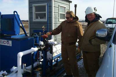
| Figure 6 Richard Pancake, TORP engineer from the University of Kansas (left) and Kevin Axelson, Foreman for Murfin Drilling Co. (right), monitor pumps and pressures as CO2 moves from the large on-site storage tank into the ground through CO2 injection well #1. Approximately 1/4 million gallons of CO2 were injected from December 1 to January 31. |
 |
| Click on either photo to view a larger version | |
|---|---|
| Figure 7 Baseline survey, November 6-16 (left); First monitor survey, January 21-31 (right). |
|
 |
 |
| Click on image to view a larger version |
|---|
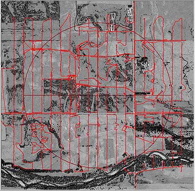
| Figure 8 Vibrator tracking log from the January 3-D data acquisition trip. Red lines are the continuous (1/second) DGPS readings on the vibrator's location. The orthophoto in the background provides some insight into the surface conditions and morphology. A total of 795 points were occupied during this survey. |
 |
|
Kansas Geological Survey, 4-D Seismic Monitoring of CO2 Injection Project Placed online Feb. 3, 2004 Comments to webadmin@kgs.ku.edu The URL is HTTP://www.kgs.ku.edu/Geophysics/4Dseismic/Reports/Jan28_2004/index.html |