|
|
|
|
Sept. 2003 GPS Field Work |
|
|
|||
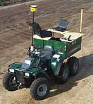
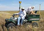
In-field: September 2-5, 2003As part of the 4-D seismic study of the CO2 injection pilot project at the Colliver Lease near Russell, Kansas, a digital terrain map is being generated using a Trimble DGPS system. Development of a high-resolution digital map of actual shot and receiver locations based on surface access is critical for pre-survey modeling and design. Stations that cannot be occupied due to access problems need to be identified, with new locations (generally offset from the ideal) incorporated into final designs and survey parameters. To minimize the adverse affect of inaccessible stations on fold and azimuthal and offset distribution it is sometimes necessary to locate replacement stations in particular directions and at specific distances from the receiver grid. For 4-D seismic surveys to be effective it is imperative that each shot and receiver station be accurately re-occupied during each time-lapse 3-D survey, effectively minimizing any changes in the recorded data not related to the injection of CO2. To that end, the digital terrain map will provide absolute re-occupation of sources and receivers throughout this six-year program.Data acquisition on this project will likely be carried out at night to minimize surface noise associate with wind and cultural activities (vehicle traffic). It is imperative that our seismic activities minimally impact current and future agricultural activities within the affected 1 square mile. With that, a digital tracking log is being built to help guide the vibratory source (13,000 lb center articulated, four-wheel-drive vehicle with >3 psi ground pressure) around the site, avoiding fences, ditches, pipelines, etc. and minimizing ground compaction and number of miles traveled through tilled farm fields. It is our assumption that limited-sight conditions will likely be present during some of the 12 different 3-D surveys throughout this six-year program. The vibrator will be outfitted with a notebook computer and high-resolution GPS, which will direct the operator from point to point when weather or night operations permit little or no visibility. To build this digital terrain map David Laflen and Brett Bennett, KGS researchers, developed a DGPS mapping system which included a six-wheel-drive ATV, Trimble DGPS, Garmin GPS, and notebook computer (Figure 1). Aided by orthophotos and topo maps the two researchers drove and digitally mapped the "best" vibrator route (Figure 2). Key priorities were minimal ground disturbance and best path around obstacles in all weather conditions. The digital mapping system was developed and assembled at the Kansas Geological Survey's fabrication facility. This modular system uses custom software interfaced to two GPS receivers, allowing real time placement and guidance referenced to orthophotos (digital, high-resolution aerophotos) and digital topo maps. |
|
|
Figure 1--DGPS Mapping System. A larger version
of this photo is available.
|
Figure 2--Route Mapping. A larger version
of this photo is available.
|
|
A preliminary tracking log provides an overview of the route most easily traversed by
the ATV and that the researchers felt would accommodate the vibrator in all weather
(Figure 3). The red lines track the path followed by the digital mapping unit.
The blue dots are the ideal shot station locations. With the western two-thirds
completed, all but about 10% of the shot stations are easily accessible. It is
anticipated that with some minor dozer work this missing 10% in the western two-thirds
could be reduced to less than 5%. Once this preliminary mapping is complete, manual
editing will produce a uniform route with location accuracy around 5 cm.
Figure 3--Preliminary Tracking Log. A larger version of this photo is available.
|
|
|
Kansas Geological Survey, 4-D Seismic Monitoring of CO2 Injection Project Placed online Sept. 8, 2003 Comments to webadmin@kgs.ku.edu The URL is HTTP://www.kgs.ku.edu/Geophysics/4Dseismic/Photos/sep03.html |